SsangYong Musso. Manual - part 165
1F-244 ENGINE CONTROLS
SSANGYONG Y158
Circuit Description
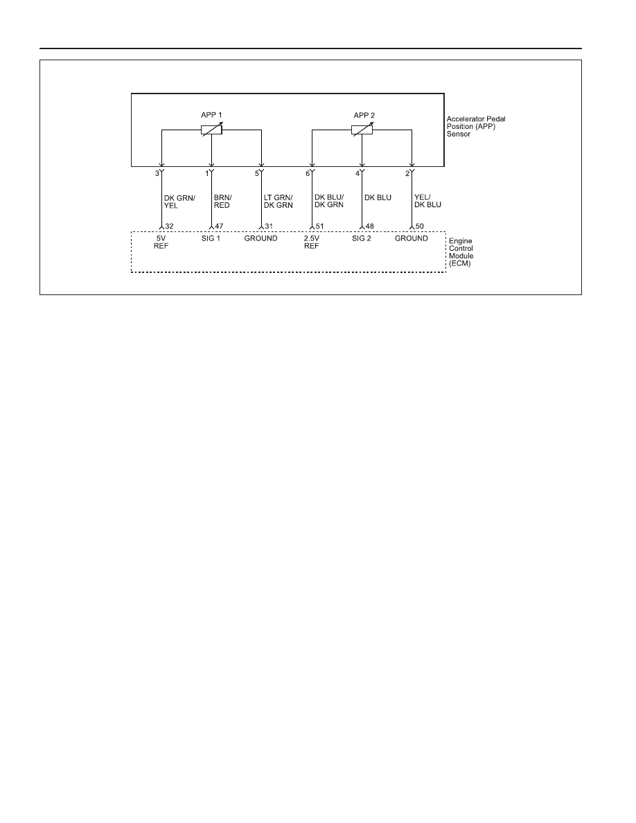
The Engine Control Module (ECM) supplies a 5 or 2.5
volt reference signal and a ground to the Accelerator
Pedal Position sensor 1 or 2. The ECM calculates the
accelerator pedal position by monitoring the voltages
on these signal lines. The APP sensor output changes
as the accelerator pedal is moved. The outputs of the
APP sensor 1 and sensor 2 are low, about 0.4 - 0.7
volts and 0.2 - 0.35 volts respectively at the closed
throttle posi-tion. As pushing the accelerator pedal, the
output in-creases so that the output voltages will be
about 4.3 - 4.8 volts and 2.1 - 2.4 volts individually when
accelerating fully with the kickdown, at Wide Open
Throttle (WOT).
Conditions for Setting the DTC
•••••
Ignition ON.
•••••
Electrical system protection is not active.
Action Taken When the DTC Sets
•••••
The Malfunction Indicator Lamp (MIL) will illuminate
after two consecutive driving cycles in which the diag-
nostic runs with the fault active.
•••••
The ECM will record operating conditions at the time
the diagnostic fails. This information will be stored in
the Freeze Frame and Failure Records buffers.
•••••
A history DTC is stored.
Conditions for Clearing the MIL/DTC
•••••
The MIL will turn off after three consecutive driving
cycles in which the diagnostic runs without a fault.
•••••
A history DTC will clear after 40 consecutive warm-
up cycles without a fault.
•••••
The DTC(s) can be cleared using the scan tool.
DIAGNOSTIC TROUBLE CODE (DTC) P0220
ACCELERATOR PEDAL POSITION SENSOR MALFUNCTION
Diagnostic Aids
If a DTC P0220 cannot be duplicated, the information
included in the Freeze Frame data can be useful. Use
the scan tool information data to determine the status
of the DTC. If the DTC occurs intermittently, using the
Diagnostic table may help isolate the problem.
Test Description
Number(s) below refer to the step number(s) on the
Diagnostic Table.
1. The Euro On-Board Diagnostic (EOBD) System
Check prompts the technician to complete some
basic checks and store the freeze frame and failure
records data on the scan tool if applicable. This
creates an electronic copy of the data taken when
the malfunction occurred. The information is then
stored on the scan tool for later reference.
3. Normal APP 1 voltage when the throttle plates are
ful-ly closed is between 0.4 - 0.7 volts. A sensor
will display a higher voltage when the sensor is stuck
or a circuit is faulty.
4. Normal APP 2 voltage when the throttle plates are
fully closed is between 0.2 - 0.35 volts. A sensor
will display a higher voltage when the sensor is stuck
or a circuit is faulty.
5. If DTC P0220 cannot be duplicated, the information
included in the Freeze Frame / Failure Records data
can be useful. Use the scan tool DTC information
data to determine the status of the DTC.
6. A disconnected APP sensor should not display a
voltage reading on the scan tool. An amount less
than the specified value is normal.
YAA1F630