SsangYong Musso. Manual - part 155


  Index      SsangYong     SsangYong Musso - service repair manual


Search            


Content   ..  153  154  155  156   ..


SsangYong Musso. Manual - part 155


1F-204  ENGINE CONTROLS

SSANGYONG  Y158

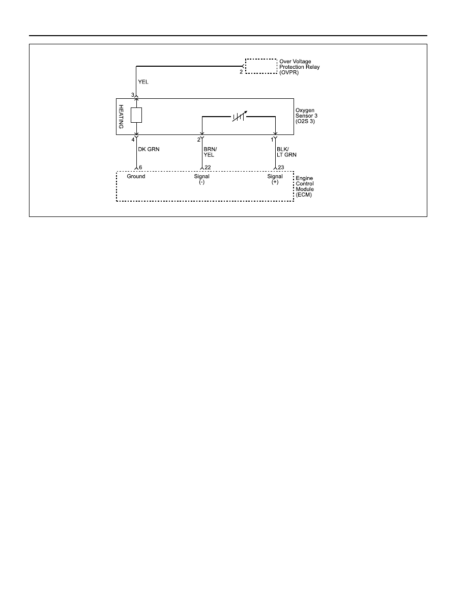
DIAGNOSTIC TROUBLE CODE (DTC) P0155-206

O2 BANK 2 SENSOR 3 HEATER SHORT  CIRCUIT TO BATTERY

 (3.2L DOHC)

Circuit Description

In order to control emissions, a catalytic converter is
used to convert harmful emissions into harmless water
vapor and carbon dioxide.

The Engine Control Module (ECM) has the ability to
monitor this process by using a Heated Oxygen Sensor
(O2S 3). The O2S 3 produces an output signal which
indicates the storage capacity of the catalyst. This in
turn indicates the catalyst’s ability to convert exhaust
emissions effectively.

If the O2S 3 pigtail wiring, connector, or terminal is
damaged, the entire O2S 3 assembly must be replaced.
Do not attempt to repair the wiring, connector, or
terminals. In order for the sensor to function properly, it
must have a clean air reference provided to it. This clean
air reference is obtained by way of the O2S 3 wire(s).

Any attempt to repair the wires, connector, or terminal
and degrade the O2S 3 performance.

Conditions for Setting the DTC

•••••

Current is between 3 ampares and 6 ampares
(depending on driver condition).

•••••

Output stage is active.

Action Taken When the DTC Sets

•••••

The Malfunction Indicator Lamp (MIL) will illuminate
after two consecutive driving cycles in which the diag-
nostic runs with the fault active.

YAB1F150

•••••

The ECM will record operating conditions at the time
the diagnostic fails. This information will be stored in
the Freeze Frame and Failure Records buffers.

•••••

A history DTC is stored.

Conditions for Clearing the MIL/DTC

•••••

The MIL will turn off after three consecutive driving
cycles in which the diagnostic runs without a fault.

•••••

A history DTC will clear after 40 consecutive warm-
up cycles without a fault.

•••••

The DTC(s) can be cleared by using the scan tool.

Diagnostic Aids

Check for the following conditions:

An intermittent may be caused by a rubbed-through wire
insulation or a wire contacting the exhaust.

Check for a poor connection or a damaged harness and
inspect the harness connectors for the following
conditions:

•••••

Improper mating

•••••

Broken locks

•••••

Improperly formed

•••••

Damaged terminals

•••••

Poor terminal-to-wire connection

•••••

Damaged harness

ENGINE CONTROLS  1F-205

SSANGYONG  Y158

1

Step

Action

Value(s)

Yes

No

DTC P0155-206 O2 Bank 2 Sensor 3 Heater Short Circuit to Battery (3.2L DOHC)

-

 Go to Step 2

Go to “Euro

On-Board

Diagnostic

System Check”

2

3

4

-

 Go to Step 7

-

-

 Go to Step 7

-

-

 Go to Step 8

 Go to Step 2

5

6

7

8

Perform an Euro On-Board Diagnostic (EOBD) System
Check.
Is the system check complete?

1. Turn the ignition ON, with the engine OFF.
2. Install a scan tool.
3. Operate the vehicle within the Freeze Frame

Conditions for Setting the DTC as noted.

Does the heater ampere within the specified value?
1. Turn the ignition OFF.
2. Disconnect the O2S 3 electrical connector.
3. Turn the ignition ON, with the engine OFF.
4. With a test light connected to ground, probe the O2S

3 electrical connector, terminal 4.

Does the test light illuminate?
1. Disconnect the ECM electrical connector.
2. Check the short to voltage between O2S 3 electrical

connector, terminal 4 and ECM electrical connector,
terminal 6 and repair as necessary.

Is a repair complete?
Replace the O2S 3.
Is the repair complete?
1. Turn the ignition switch OFF.
2. Replace the ECM.
Is the repair complete?
1. Using the scan tool, clear the Diagnostic Trouble

Codes (DTCs).

2. Start the engine and idle at normal operating

temperature.

3. Operate the vehicle within the Conditions for setting

this DTC as specified in the supporting text.

Does the scan tool indicate that this diagnostic has ran
and passed?
Check if any additional DTCs are set.
Are any DTCs displayed that have not been diagnosed?

-

 Go to Step 7

Go to Step 6

0.2 - 2 amps

 Go to Step 3

Go to Step 5

Test Description

Number(s) below refer to the step number(s) on
theDiagnostic Table.

1. The Euro On-Board Diagnostic (EOBD) System

Ckeck prompts the technician to complete some
basic checks and store the freeze frame and failure
record data on the scan tool if applicable. This

creates an electronic copy of the data taken when
the malfunction occurred. The information is then
stored on the scan tool for later reference.

4. If the test light is still on after disconnecting the

ECM connector, the wire between the heater and
the ECM is short to voltage. If the test light goes
off, the ECM is at fault.

-

 Go to Step 4

Go to

“Diagnostic

Aids”

-

Go to

applicable

DTC table

System OK

1F-206  ENGINE CONTROLS

SSANGYONG  Y158

DIAGNOSTIC TROUBLE CODE (DTC) P0155-207

O2 BANK 2 SENSOR 3 HEATER SHORT  CIRCUIT TO GROUND OR OPEN

(3.2L DOHC)

Circuit Description

In order to control emissions, a catalytic converter is
used to convert harmful emissions into harmless water
vapor and carbon dioxide.

The Engine Control Module (ECM) has the ability to
monitor this process by using a Heated Oxygen Sensor
(O2S 3). The O2S 3 produces an output signal which
indicates the storage capacity of the catalyst. This in
turn indicates the catalyst’s ability to convert exhaust
emissions effectively.

If the O2S 3 pigtail wiring, connector, or terminal is
damaged, the entire O2S 3 assembly must be replaced.
Do not attempt to repair the wiring, connector, or
terminals. In order for the sensor to function properly, it
must have a clean air reference provided to it. This clean
air reference is obtained by way of the O2S 3 wire(s).

Any attempt to repair the wires, connector, or terminal
and degrade the O2S 3 performance.

Conditions for Setting the DTC

•••••

O2S 3 voltage is less than 2 volts for ground.

•••••

O2S 3 voltage is less than 3 volts for open.

•••••

Output stage is inactive.

Action Taken When the DTC Sets

•••••

The Malfunction Indicator Lamp (MIL) will illuminate
after two consecutive driving cycles in which the diag-
nostic runs with the fault active.

•••••

The ECM will record operating conditions at the time
the diagnostic fails. This information will be stored in
the Freeze Frame and Failure Records buffers.

•••••

A history DTC is stored.

Conditions for Clearing the MIL/DTC

•••••

The MIL will turn off after three consecutive driving
cycles in which the diagnostic runs without a fault.

•••••

A history DTC will clear after 40 consecutive warm-
up cycles without a fault.

•••••

The DTC(s) can be cleared by using the scan tool.

Diagnostic Aids

An intermittent may be caused by rubbed-through wire
insulation or a wire contacting the exhaust.

•••••

Exhaust system - Inspect the exhaust system for
leaks. Check the exhaust between the three-way cat-
alytic converter and the flange for leaks, corrosion,
or for loose or missing hardware and repair as neces-
sary.

•••••

Poor connection or damaged harness - Ensure that
the O2S 3 pigtail is not contacting the exhaust.

•••••

Check for the following conditions:

•••••

improper mating

•••••

Broken locks

•••••

Improperly formed

•••••

Damaged terminals

•••••

Poor terminal-to-wire connection

•••••

Damaged harness

YAB1F150

ENGINE CONTROLS  1F-207

SSANGYONG  Y158

1

Step

Action

Value(s)

Yes

No

DTC P0155-207 O2 Bank 2 Sensor 3 Heater Short Circuit to Ground or Open (3.2L DOHC)

-

 Go to Step 2

Go to “Euro

On-Board

Diagnostic

System Check”

2

3

4

-

 Go to Step 10

Go to Step 6

-

 Go to Step 10

Go to Step 7

-

 Go to Step 10

-

5

6

7

8

Perform an Euro On-Board Diagnostic (EOBD) System
Check.
Is the system check complete?

1. Turn the ignition ON, with the engine OFF.
2. Install a scan tool.
3. Operate the vehicle within the Freeze Frame

Conditions for Setting the DTC as noted.

Does the heater ampere within the specified value?
1. Turn the ignition OFF.
2. Disconnect the O2S 3 electrical connector.
3. Turn the ignition ON.
4. With a test light connected to B+, probe the O2S 3

electrical connector, terminal 4.

Does the test light illuminate?
1. Check an open or short to ground in wiring between

the Over Voltage Protection Relay (OVPR) electrical
connector, terminal 2 and O2S 3 electrical
connector, terminal 3.

2. Repair as necessary.
Is the repair complete?
Check the poor connection at the OVPR connector
terminal 2 and O2S 3 electrical connector, terminal 3.
Did the terminal require replacement?
1. Check an open or short to ground in wiring between

the O2S 3 electrical connector, terminal 4 and O2S 3
ground circuit, terminal 6.

2. Repair as necessary.
Is the repair complete?
Check the poor connection at the O2S 3 connector
terminal 4 and O2S 3 ground circuit, terminal 6.
Did the terminal require replacement?
Replace the O2S 3.
Is the repair complete?
1. Turn the ignition switch OFF.
2. Replace the ECM.
Is the repair complete?

-

 Go to Step 10

Go to Step 5

0.2 - 2.0 amps

 Go to Step 3

Go to Step 8

•••••

Intermittent test - Observe the O2S 3 on the scan
tool while moving related connections and the wiring
harness with the ignition ON. If the failure is induced,
the O2S 3 display will change. This may help isolate
the location of the malfunction.

Test Description

Number(s) below refer to the step number(s) on the
Diagnostic Table.

1. The Euro On-Board Diagnostic (EOBD) System

Check prompts the technician to complete some
basic checks and store the freeze frame and failure
records data on the scan tool if applicable. This
creates an electronic copy of the data taken when
the malfunction occurred. The information is then
stored on the scan tool for later reference.

4. This step checks for an open or shorted.

9

-

 Go to Step 10

 Go to Step 9

-

 Go to Step 10

-

-

 Go to Step 4

Go to

“Diagnostic

Aids”


Content   ..  153  154  155  156   ..