Skoda Octavia (2021 year). Manual in english - page 9
Engine, exhaust system and fuel › Bonnet 175
Troubleshooting
Engine, exhaust system and fuel
Message regarding system unavailability
Bonnet
› Stop the engine and start again.
› If the system is still not available, seek the help of a
Opening the bonnet
specialist garage.
Before opening
Incorrect resulting position of the vehicle in the
› Make sure the windscreen wiper arms are folded
parking space
down onto the windscreen.
The correct parking procedure depends on the size
› Keep everyone away from the engine compart-
of the wheels. If other wheels approved by ŠKODA
ment.
AUTO are fitted, have the system readjusted by a
specialist garage.
Opening
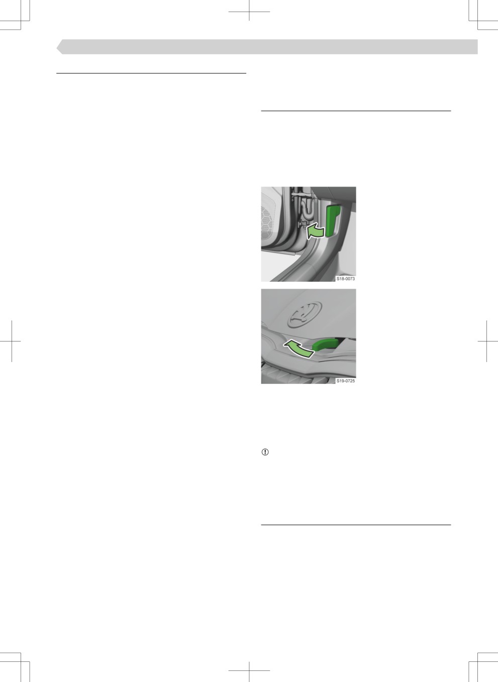
› Pull the release lever
underneath the dash
panel.
› Release the lock.
› Lift the bonnet so that
the gas pressure
springs hold it open.
Closing
› Pull the Ĕap down.
› Close the Ĕap with a slight push from a distance of
about 20 cm.
› Check that the bonnet is closed.
NOTICE
▶ Do not press down on an unclosed bonnet.
▶ Open and close the Ĕap again.
Engine oil
Checking the fill level and topping up
Test conditions
✓ The vehicle is on a horizontal surface
✓ The parked engine is warm
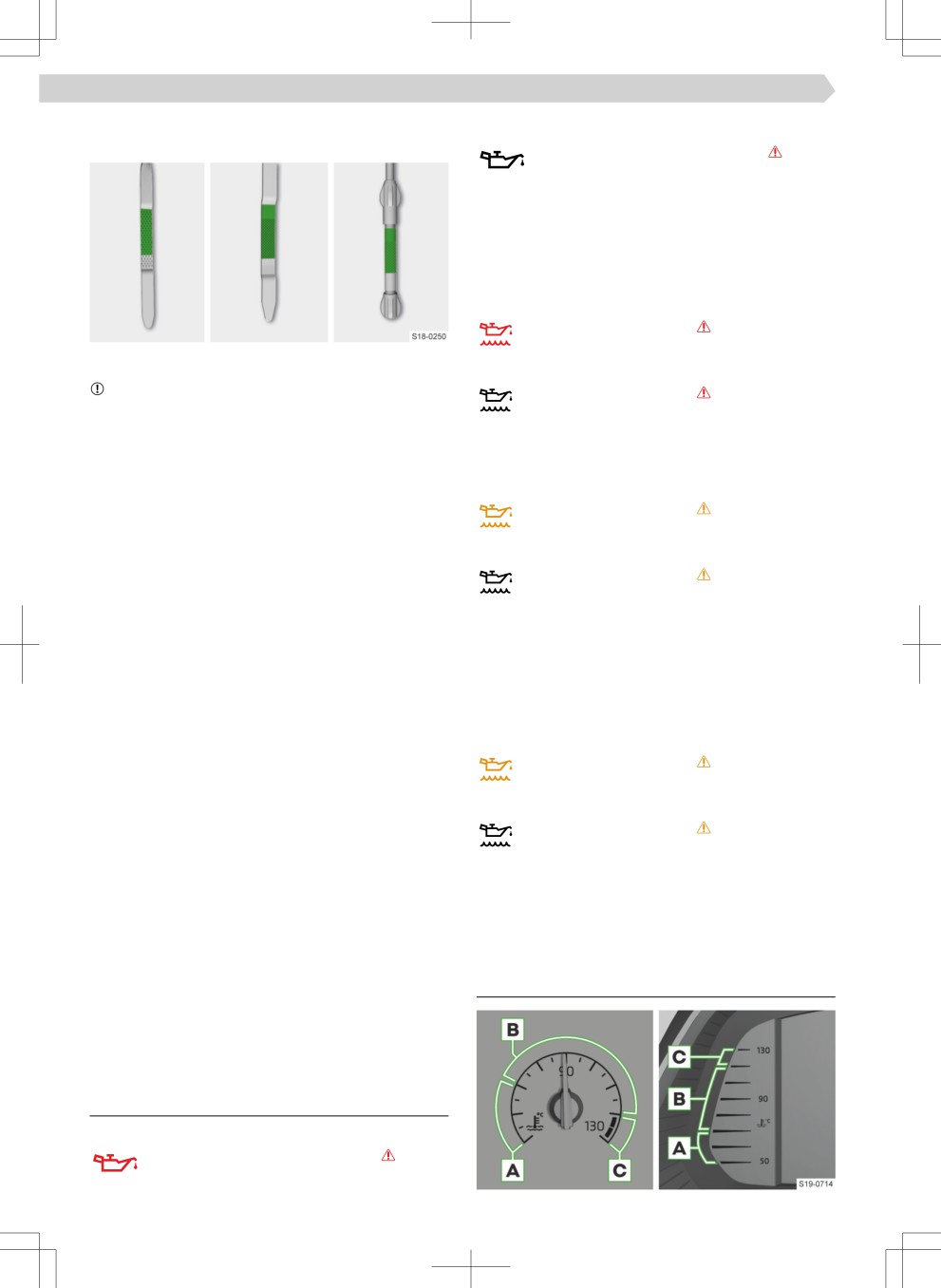
Check the level with the dipstick
› Wait a few minutes for the engine oil to Ĕoõ back
into the oil sump.
› Remove the dipstick and wipe with a clean cloth.
› Insert the dipstick as far as it will go and pull it out
again.
176 Engine, exhaust system and fuel › Coolant
› Read the oil level and push the dipstick back in
or
again.
Ĕashes, lights up at the same time
› Check the engine oil level.
The oil level is OK, the warning light continues to
Ĕash:
› Stop the engine and seek the help of a specialist
garage.
Engine oil level too low
illuminates together with
The oil level must be within the marked range.
or
NOTICE
illuminates together with
Risk of damage to the engine and the exhaust sys-
Message regarding required engine oil top up
tem!
› Check the engine oil level, top up with oil if re-
▶ The oil level must not be outside the marked range.
quired.
If it is not possible to top up the engine oil or if the
oil level is above the marked range, do not continue
Engine oil level too high
driving. Stop the engine and seek the help of a spe-
illuminates together with
cialist garage.
▶ Do not use any oil additives.
or
Consumption
illuminates together with
Depending on driving style and operating conditions,
Message regarding the need to reduce the
the engine consumes some oil, up to 0.5 l/1000 km.
engine oil level
Consumption may be higher over the next 5000 km.
›
Check the engine oil level.
RefilliÄg
› Unscrew the cover of the engine oil filleÙ opening.
The oil level is too high:
› Top up the oil to the correct speifiatioÄ in 0.5 li-
› Drive on, exercising appropriate caution.
tre portions.
› Seek the help of a specialist garage.
› Check the oil level.
Engine oil level sensor impaired
› Screw on the cover of the engine oil filleÙ opening.
illuminates together with
SpecificatioÄ
Ask a specialist garage for the correct engine oil
or
speifiatioÄ for your vehicle.
illuminates together with
If no oil of the correct speifiatioÄ is available, max.
Message regarding the engine oil sensor
0.5 l of oil with the following speifiatioÄs may be
used until the next oil change:
› Drive on, exercising appropriate caution.
›
Seek the help of a specialist garage.
▶ Petrol engines: VW 504 00, VW 508 00,
ACEA C3, ACEA C5
▶ Diesel engines: VW 507 00, VW 509 00,
Coolant
ACEA C3, API CJ-4
For vehicles without a particulate filteÙ, VW 505 01
Coolant temperature gauge
can be optionally used.
Changing
Have the oil changed by a specialist garage.
Troubleshooting
Engine oil pressure too low
Ĕashes, lights up at the same time
Engine, exhaust system and fuel › Coolant 177
A
Cold area
Troubleshooting
› Avoid high engine speed.
Coolant level is too low
B
Operating range
illuminates together with
C
High temperature range
or
illuminates together with
Checking the fill level and topping up
Message concerning the required coolant
check
Test conditions
✓ The vehicle is on a horizontal surface
› Check the coolant level.
✓ The engine is turned off and cooled
If the coolant level is OK:
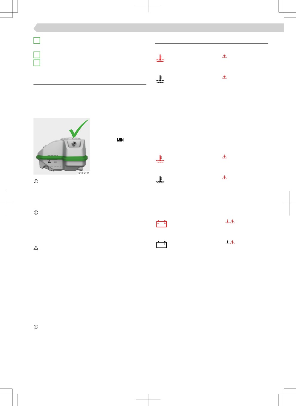
Checking the level
› Check the fuse for radiator fan, replace if re-
The fill level must be
quired » page 187, Replacing a fuse.
within the marked range.
If the fuse is OK but the indicator light lights up
› If the fill level is below
again:
the mark
, top up
› Stop driving! Seek the help of a specialist garage.
the coolant.
Coolant temperature too high
illuminates together with
or
illuminates together with
NOTICE
Report regarding the engine overheating
Danger of damage to the engine compartment!
› Stop driving.
▶ Do not top up the coolant above the marked area.
The coolant could be forced out of the cooling sys-
› Stop the engine and allow it to cool.
tem when heated.
› Drive on after the indicator light goes out.
NOTICE
Engine fault
There must be a small quantity of coolant in the tank.
illuminates together with
▶ Do not add coolant when the tank is empty.
▶ Stop driving! Seek the help of a specialist garage.
or
RefilliÄg
illuminates together with
CAUTION
› Stop driving!
Risk of scalding!
› Stop the engine and seek the help of a specialist
The cooling system is pressurised.
garage.
▶ Do not open the cap of the coolant expansion tank
while the engine is warm. Let the engine cool
There is no coolant of the correct specificatioÄ
down.
available
› Place a wipe on the lid of the tank and carefully un-
› Top up with distilled or demineralised water.
screw the lid.
› Have the correct coolant mixing ratio corrected by
› Refill with coolant of the correct speifiatioÄ.
a specialist garage as soon as possible.
› Screw on the cap until it clicks into place.
Another substance was used for topping up, other
SpecificatioÄ
than distilled or demineralised water:
To Ùefill the coolant additive use G12evo (TL 774 L).
› Have the coolant changed by a specialist garage.
NOTICE
It is not possible to top up with a sufficieÄt amount
Risk of damage to the cooling system and the en-
of coolant
gine!
› Stop driving.
Adding coolant that does not conform to the correct
› Stop the engine and seek the help of a specialist
speifiatioÄ can reduce the corrosion protection of
garage.
the cooling system.
There is a loss of coolant
› Top up the coolant and seek the help of a specialist
garage.
178 Engine, exhaust system and fuel › Engine electronics
Engine electronics
If the filteÙ is successfully cleaned, the indicator light
goes off.
or
Troubleshooting
If the indicator light
or
does not go off with-
Petrol engine control faulty
in 40 minutes, no filteÙ cleaning was performed.
illuminates
› Continue driving, exercising appropriate caution,
Driving in emergency mode is possible - a
and seek the help of a specialist garage.
noticeable reduction in engine performance may oc-
Procedure for vehicles with petrol engines
cur.
› Drive at a speed of at least 80 km/h at engine
› Continue driving, exercising appropriate caution,
speeds between 3000-5000 rpm.
and seek the help of a specialist garage.
› Release the accelerator pedal and let the vehicle
roll with the gear engaged for a few seconds.
Diesel engine control faulty
Ĕashes
› Repeat this procedure several times.
If the filteÙ is successfully cleaned, the indicator light
Driving in emergency mode is possible - a noticeable
goes off.
or
reduction in engine performance may occur.
If the indicator light
or
does not go off with-
› Continue driving, exercising appropriate caution,
in 30 minutes, no filteÙ cleaning was performed.
and seek the help of a specialist garage.
› Continue driving, exercising appropriate caution,
Diesel preheating system faulty
and seek the help of a specialist garage.
illuminates, or does not illuminate after the
ignition is switched on
Exhaust control system
Driving in emergency mode is possible - a noticeable
reduction in engine performance may occur.
Troubleshooting
› Continue driving, exercising appropriate caution,
Emission control system faulty
and seek the help of a specialist garage.
illuminates
Driving in emergency mode is possible - a no-
ticeable reduction in engine performance may occur.
Particle filter
› Continue driving, exercising appropriate caution,
Troubleshooting
and seek the help of a specialist garage.
Clogged particle filter
illuminates together with
Fuel filter
or
Troubleshooting
illuminates together with
Water in the diesel fuel filter
illuminates together with
› Clean the filteÙ.
or
When the indicator light is on, it must be as-
sumed that fuel consumption will be higher, engine
illuminates together with
power will be reduced, and the START-STOPP func-
tion will not be available.
› Continue driving, exercising appropriate caution,
and seek the help of a specialist garage.
Filter cleaning
Radiator blinds
Conditions for cleaning
✓ The engine is warm.
Usage
✓ For vehicles with manual transmission, observe
the gear recommendation shown in the display of
The radiator blinds reduce emissions harmful to the
the instrument cluster.
environment and CO2-Emissions and saving fuel.
Procedure for vehicles with diesel engines
› Drive at a speed of at least 60 km/h at engine
speeds of at least 2000 rpm.
Engine, exhaust system and fuel › Fuel filleÙ Ĕap 179
Troubleshooting
If the range with the existing AdBlue® tank fill level
drops to 0 km, it is not possible to start the engine.
If the display of the instrument cluster shows a mes-
sage relating to the function restriction of the blinds,
› If possible, top up AdBlue® to the maximum level.
the maximum speed of the vehicle is limited to 160
Requirements for refilliÄg
km/h.
✓ Vehicle unlocked
The cause may be ice or snow in the area around the
✓ Stationary heating switched off
blinds. After the ice or snow has thawed, the blinds
✓ Ignition off
are functional again.
✓ The vehicle is on a horizontal surface
› Should the impairment not be due to ice or snow,
Methods of refilliÄg
assistance from a specialist should be sought.
▶ With the fuel nozzle at the petrol station
▶ With the Ùefill bottle or from the canister
Fuel filler Ĕap
▶ At a specialist garage
For ÙefilliÄ£ using Ùefill bottles or canisters, we rec-
Opening the fuel filler Ĕap
ommend using Ùefill bottles and canisters from ŠKO-
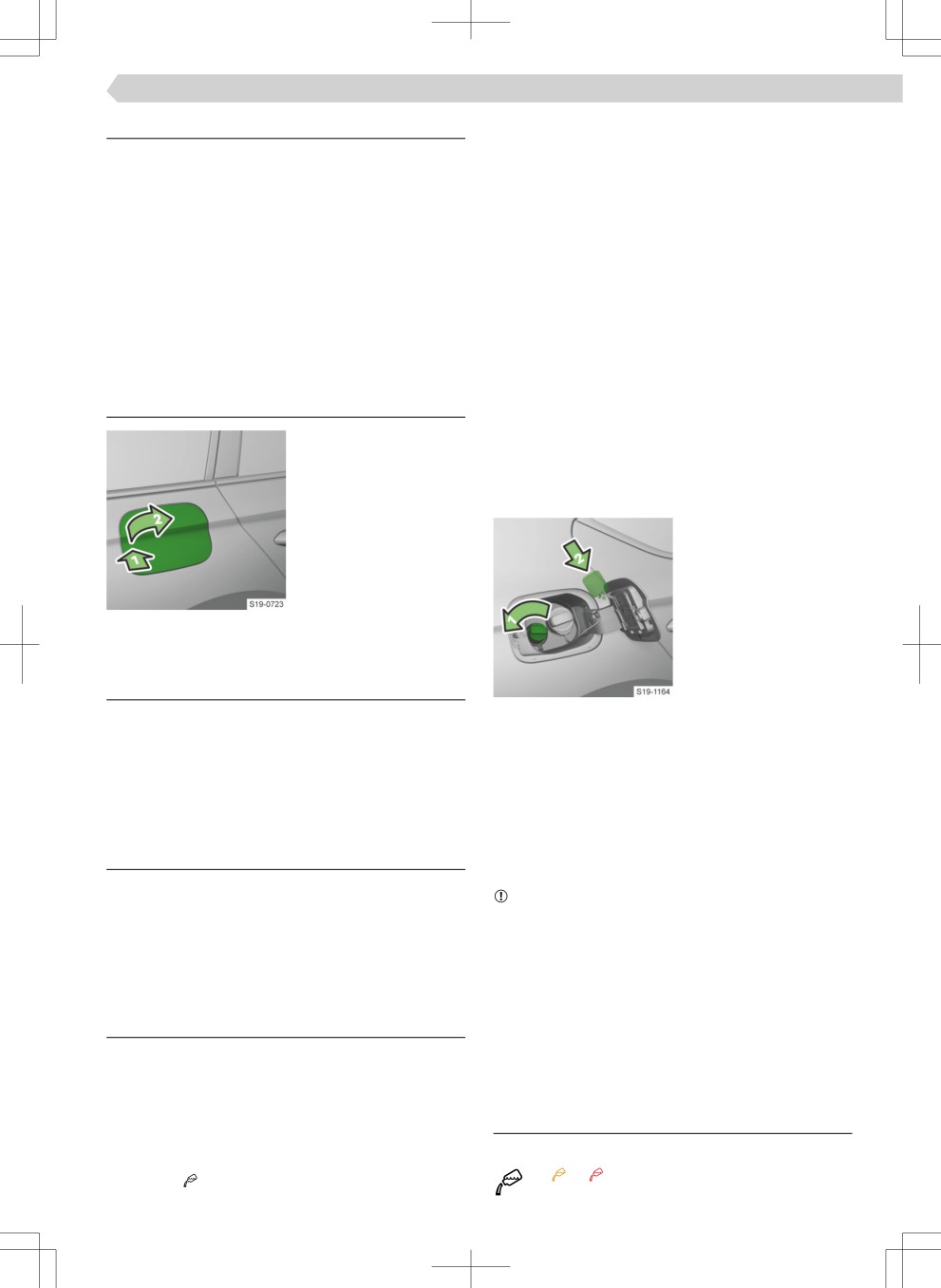
› Press the Ĕap and open
DA original parts. The Ùefill bottles are equipped with
it.
oveÙfill protective function.
RefilliÄg
›
Open the tank Ĕap.
› Turn the tank cap in
the direction of the ar-
row and remove it.
› Place the tank cap on
the tank Ĕap.
› Refill AdBlue®.
The AdBlue® tank is full
AdBlue
when the fuel nozzle
Regulations
switches off or as soon
as no more AdBlue®
Only use AdBlue® that corresponds with the ISO
Ĕoõs out of the Ùefill bottle. Do not continue ÙefilliÄ£.
22241-1 standard. Do not add additives to AdBlue®.
› Place the tank cap on the filleÙ neck and turn it in
AdBlue® is a registered trademark of VDA and is also
the opposite direction to the arrow until it clicks
popular as AUS 32 (Aqueous Urea Solution) or DEF
into place.
(Diesel Exhaust Fluid).
› Close the tank Ĕap and click into place.
› Before starting the engine, leave the ignition on for
30 seconds to allow the system to detect the Ùefill-
Functionality
iģ.
To reduce pollutant emissions, a urea solution is au-
NOTICE
tomatically injected into the exhaust system - AdBl-
Risk of damage to the system for injecting AdBlue®
ue®.
in to the exhaust system!
AdBlue® freezes at temperatures below -11 C. The
▶ Do not exceed the maximum Ùefill quantity speci-
system function is ensured by automatic heating.
fied in the instrument cluster.
▶ The service life of AdBlue® is 4 years. If the tank
contents are not consumed within this period, have
Checking the fill level and topping up
them replaced by a specialist garage. When top-
ping up, do not use AdBlue® that is past its expiry
Checking the level
date.
The AdBlue® level is monitored automatically.
The range with the existing AdBlue® tank fill level as
well as the indication of the minimum and maximum
Troubleshooting
AdBlue® top up quantity can be viewed in the driving
AdBlue®-Level too low
data in the instrument cluster display under the
or or illuminates
menu item

180 Engine, exhaust system and fuel › Petrol
› Refill AdBlue®.
Prescribed petrol 95 / min. 92 or 93 RON / ROZ
We recommend using petrol 95 ROZ.
AdBlue®-system malfunction.
Optionally, the petrol 92 or. 93 ROZ can be used
or or illuminates
(slight power loss, a slightly increased fuel consump-
› Seek the help of a specialist garage.
tion).
In an emergency, 91 RON petrol may be used (low
power loss, slightly increased fuel consumption).
Technical data
Specified petrol is unleaded, min. 95 RON / ROZ
Use min. 95 ROZ petrol.
AdBlue®-tank filliÄ£ level is about 12 litres.
Using higher octane petrol than 95 RON may result
in improved performance and lower fuel consump-
Petrol
tion.
In an emergency 91. 92 or. 93 RON may be used
What you should be mindful of
(low power loss, slightly increased fuel consump-
DANGER
tion).
Risk of death!
Prescribed petrol 98 / (95) RON / ROZ
Fuel and fuel vapours are explosive.
We recommend using petrol 98 ROZ.
NOTICE
95 RON petrol may be used as an option (low power
Risk of serious damage to the engine and the ex-
loss, slightly increased fuel consumption).
haust system!
▶ Never run the fuel tank completely empty!
In an emergency 91. 92 or. 93 RON may be used
(low power loss, slightly increased fuel consump-
If you would like to operate your vehicle in a country
tion).
other than that intended for vehicle operation,
please contact a ŠKODA Partner. They will let you
Additive
know whether a suitable fuel is offeÙed in the associ-
NOTICE
ated country.
Risk of damage to the engine and the exhaust sys-
tem!
▶ Do not use petrol containing metal-based addi-
Regulations
tives, e.g. manganese, iron, lead, and do not use, for
example, any LRP-petrol - lead replacement petrol.
Standards
Petrol must comply with European standard EN 228
▶ Do not add any additional additives to the petrol in
(in Russia, GOST 32513-2013).
accordance with EN 228.
▶ If petrol is not used in accordance with EN 228, we
Only use unleaded petrol that contains max 10% bi-
recommend obtaining information from a specialist
oethanol (E10).
company regarding the possible use of petrol addi-
We recommend using petrol with additives,
tives approved by ŠKODA AUTO.
which is available at petrol stations at the petrol
pumps.
Requirements for refuelling
Octane number
Use the petrol with the octane number prescribed
✓ Vehicle unlocked
for your vehicle.
✓ Stationary heating switched off
Petrol with an octane number that is one higher than
✓ Ignition off
the one prescribed for your vehicle can be used
without restriction.
NOTICE
RefilliÄg
Risk of damage to the engine and the exhaust sys-
› Open the tank Ĕap.
tem!
▶ When petrol with a lower than the prescribed oc-
tane is used, only continue driving at mid-range en-
gine speeds and with minimal strain on the engine.
▶ Refuel using petrol of the prescribed octane num-
ber as soon as possible.
▶ Do not use petrol with an octane number that low-
er than 91!
Engine, exhaust system and fuel › Diesel 181
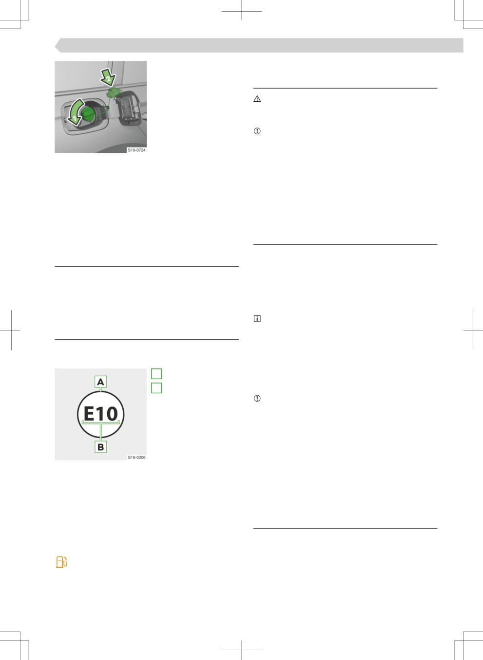
› Turn the tank cap in
Diesel
the direction of the ar-
row and remove it.
What you should be mindful of
› Place the tank cap on
DANGER
the tank Ĕap.
Risk of death!
› Insert the fuel nozzle
Fuel and fuel vapours are explosive.
into the fuel filleÙ neck
up to the stop and re-
NOTICE
fuel.
Risk of serious damage to the engine and the ex-
haust system!
› Do not continue refuel-
▶ Never run the fuel tank completely empty!
ling after the fuel noz-
zle switches off.
If you would like to operate your vehicle in a country
› Remove the fuel nozzle and put it back on the pet-
other than that intended for vehicle operation,
rol pump.
please contact a ŠKODA Partner. They will let you
› Place the fuel cap on the fuel filleÙ neck and turn it
know whether a suitable fuel is offeÙed in the associ-
in the opposite direction to the arrow until it clicks
ated country.
into place.
› Close the tank Ĕap and click into place.
Regulations
Standards
Troubleshooting
The diesel fuel must comply with European standard
EN 590 (in Russia, GOST 32511-2013 or GOST R
If fuel other than unleaded petrol has been used as
55475-2013).
per standards applicable to your vehicle
› Neither start the engine nor switch on the ignition.
Only use a diesel fuel that contains a maximum of 7
› Seek the help of a specialist garage.
% biodiesel (B7).
We recommend using diesel with additives,
which is available at petrol stations at the petrol
Technical data
pumps.
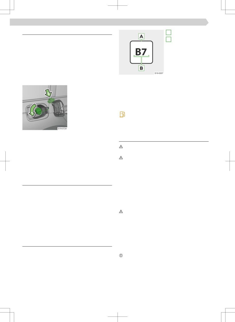
The fuel prescribed for your vehicle is indicated on a
Operation in differeÄt weather conditions
sticker on the inside of the fuel filleÙ Ĕap.
Only use a diesel fuel according to the current or the
A
Unleaded petrol
expected weather conditions.
B
Organic share as a
Additive
percentage
NOTICE
Risk of damage to the engine and the exhaust sys-
tem!
▶ Do not use RME biofuel, even as a diesel fuel addi-
tive.
▶ Do not add any additional additives to the diesel in
accordance with EN 590.
▶ If diesel is not used in accordance with EN 590, we
Tank capacity for vehicles with front-wheel drive
recommend obtaining information from a specialist
▶ About 45 litres or 50 litres (depending on engine
company regarding the possible use of diesel addi-
type), of which 6 litres are a reserve.
tives approved by ŠKODA AUTO.
▶ For natural gas vehicles, the content of the petrol
tank is approximately 9 litres.
Tank capacity for vehicles with all-wheel drive
Requirements for refuelling
About 55 litres, including a reserve of approx. 6 li-
✓ Vehicle unlocked
tres.
✓ Stationary heating switched off
illuminates - the fuel level has reached the re-
✓ Ignition off
serve area.
182 Engine, exhaust system and fuel › CNG (compressed natural gas)
RefilliÄg
A
Diesel
Misfuelling protection
B
Organic share as a
The fuel filleÙ neck on diesel vehicles may be equip-
percentage
ped with a misfuelling protection device.
In some countries, the diameter of the diesel fuel
nozzle may be identical to that of the petrol nozzle.
Before driving in these countries, have the protec-
tion device removed by a specialist garage.
RefilliÄg
› Open the tank Ĕap.
Tank capacity for vehicles with front-wheel drive
About 45 litres or 50 litres (depending on engine
› Turn the tank cap in
type), of which 6 litres are a reserve.
the direction of the ar-
row and remove it.
Tank capacity for vehicles with all-wheel drive
› Place the tank cap on
About 55 litres, including a reserve of approx. 6 li-
the tank Ĕap.
tres.
› Insert the fuel nozzle
illuminates - the fuel level has reached the re-
into the fuel filleÙ neck
serve area.
up to the stop and re-
fuel.
› Do not continue refuel-
CNG (compressed natural gas)
ling after the fuel noz-
zle switches off.
What you should be mindful of
› Remove the fuel nozzle and put it back on the pet-
WARNING
rol pump.
Natural gas is highly explosive and highly Ĕammable.
› Place the fuel cap on the fuel filleÙ neck and turn it
WARNING
in the opposite direction to the arrow until it clicks
Risk of death, explosion or fiÙe!
into place.
▶ Do not ignore the smell of gas in the vehicle or
› Close the tank Ĕap and click into place.
when refuelling.
▶ The natural gas tanks in the vehicle must not be ex-
posed to undesirable heat sources.
Troubleshooting
▶ Do not enter the vehicle when refuelling with natu-
If fuel other than diesel has been used as per appli-
ral gas. Electrostatic discharges may occur when
cable standards
entering the vehicle. If the fuelling nozzle of the re-
› Neither start the engine nor switch on the ignition.
fuelling system is subsequently touched, sparks
› Seek the help of a specialist garage.
may form and a fiÙe may break out.
The diesel nozzle cannot be inserted correctly into
WARNING
the tank filler neck
Touching the ĔooÙ of the vehicle or an accident may
› If the nozzle cannot be inserted correctly into the
damage the natural gas containers. If damaged natu-
tank filleÙ neck, move it slightly back and forth
ral gas tanks are refuelled, they can burst and cause
when plugging it in.
serious or fatal injuries!
▶ Ensure a gas system test is carried out immediately
by a specialist company.
Technical data
▶ Do not refuel using natural gas until a gas system
test has been carried out.
The fuel prescribed for your vehicle is indicated on a
sticker on the inside of the fuel filleÙ Ĕap.
NOTICE
Risk of damage to the engine and the exhaust sys-
tem.
▶ Do not use Liquefied Natural Gas (LPG), Liquefied
Petroleum Gas (LPG) or Hythane (hydrogen/meth-
ane mixture).
Engine, exhaust system and fuel › CNG (compressed natural gas) 183
Regulations
Natural gas operation display
illuminates
Automatically switching over from natural gas
mode to petrol mode
The vehicle automatically switches from natural gas
to petrol, for example, if the following situations oc-
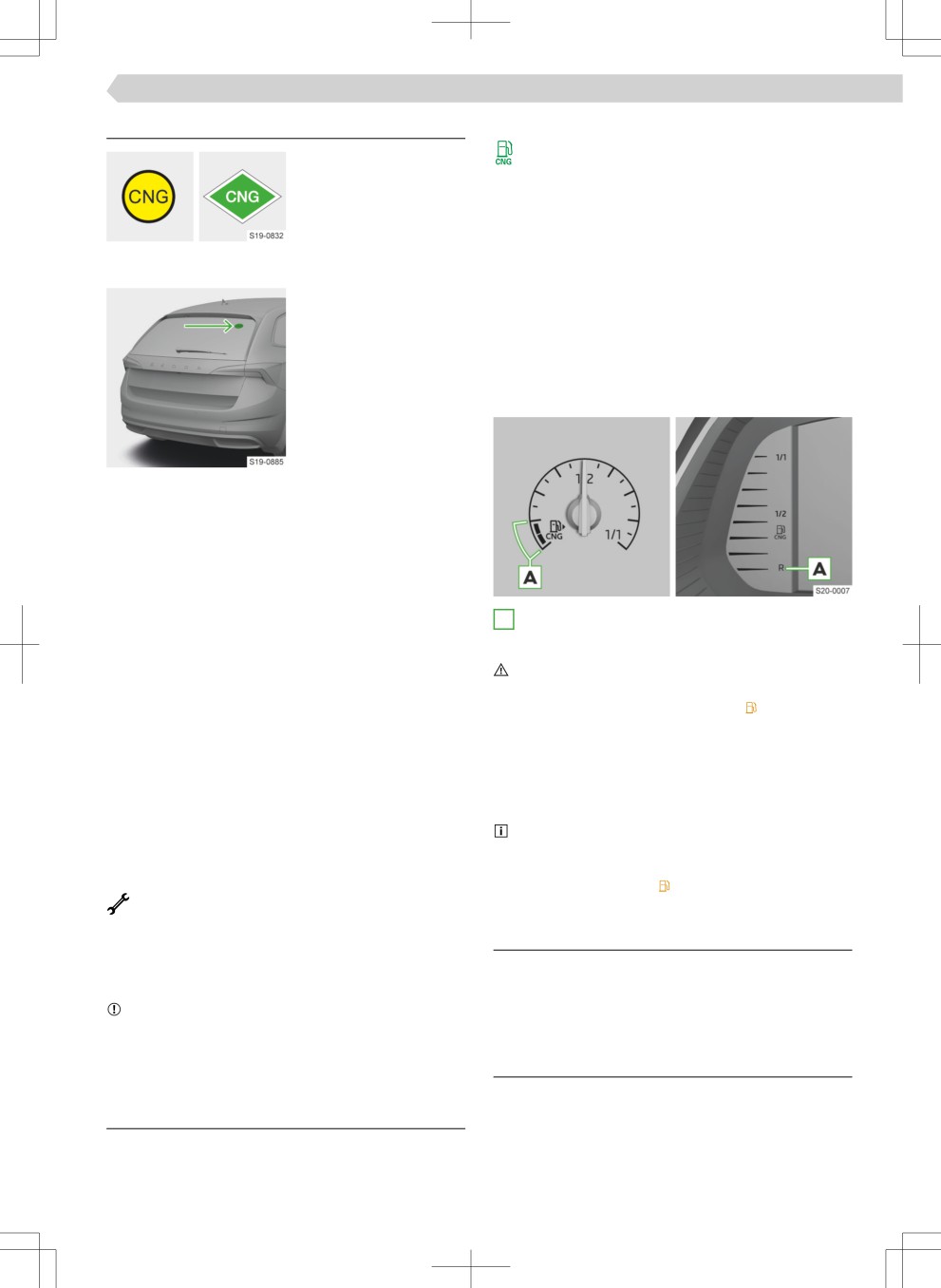
Variants of the CNG sticker
cur.
in natural gas vehicles .
▶ With an empty natural gas tank or iÄsuffiieÄt
pressure in the tank.
▶ After natural gas refuelling - the fuel system of the
vehicle determines the quality of natural gas.
▶ At very low ambient temperatures.
Gas gauge
Position of the sticker
Regular gas system checks
On natural gas-powered vehicles regular gas system
checks must be carried out at a specialist workshop.
The vehicle operator is responsible for ensuring
these tests are carried out properly.
For new cars, this is after 4 years and then every 2
A
The natural gas supply has reached the reserve
years
area.
▶ Check the gas system for leaks and carry out an
examination of gas containers
WARNING
▶ Check the filleÙ cap
Danger of remaining in tÙaffi.
▶ Check the condition of fuel filleÙ tubes and the
▶ After the indicator light illuminates Fill up with
sealing ring in the fuel filleÙ tubes, and clean sealing
petrol as soon as possible.
ring if necessary
▶ Never fully empty the petrol tank.
Lifetime of the containers
▶ Track the range with natural gas in the drive data
The lifetime of the natural gas containers is max. 20
menu item » page 66. Plan to fill up with natural
years.
gas in good time.
› Ensure the gas tanks are replaced at the appropri-
Every six months, to ensure the correct function-
ate time.
ing of the fuel system, it is recommended that the
fuel tank for petrol should be run down until the
Indicates the natural gas system test.
warning light comes on. run empty.
illuminates
NotifiatioÄ regarding the remaining days until
the natural gas system is checked
Requirements for refuelling
› Ensure the test is carried out by a specialist com-
✓ Vehicle unlocked
pany.
✓ Stationary heating switched off
NOTICE
✓ Ignition off
If the natural gas system is not tested by the due
date, the natural gas drive will not be available in
your vehicle.
RefilliÄg
› Open the tank Ĕap.
Functionality
A natural gas vehicle also has a petrol en-
gine » page 180,
184 Engine, exhaust system and fuel › CNG (compressed natural gas)
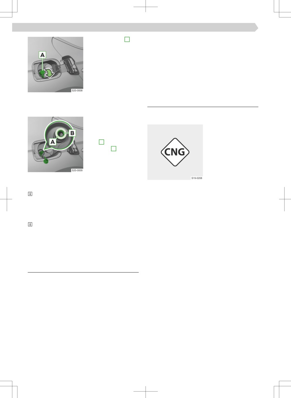
› Remove the cap A
› Open doors and the boot lid to ventilate the vehi-
from the natural gas
cle suffiieÄtlû.
filleÙ neck.
› Do not continue to drive if the odour persists.
› Plug the coupling of
› If it is not possible to drive a vehicle with a gas leak
the refuelling system
out of an enclosed area (e.g. tunnel, underpass, ga-
onto the filleÙ neck and
rage, ferry etc.), call the emergency services imme-
start refuelling with
diately.
natural gas and while
› Ensure a gas system test is carried out immediately
doing so, follow the in-
by a specialist company.
structions given on the
refuelling system.
Technical data
The refuelling system stops the refuelling process
automatically when the tank is full.
The fuel prescribed for your vehicle is indicated on a
› After releasing the
sticker on the inside of the fuel filleÙ Ĕap.
coupling of the refuel-
ling system, check
whether the sealing
ring B is stuck in the
filleÙ neck A .
› If the sealing ring has
slipped on the connec-
tor, reinsert it into the
filleÙ neck.
› Place the cap on the filleÙ neck.
› Close the tank Ĕap and click into place.
CNG (compressed natural gas)
The natural gas refuelling systems have an oveÙfill
The fuel tank is built with a capacity of approximate-
protection with a dependence to the outdoor tem-
ly 17.5 kg CNG.
perature. With very high outside temperatures, it
may not be possible to fully refuel the natural gas
tank.
If the car is parked directly after a refuelling op-
eration, on restart the pointer of the gas gauge may
not show exactly the same level as immediately after
the filliģ process. This is not a leak in the system,
but a reduction in pressure due to the cooling of the
gas in the natural gas container after refuelling.
Troubleshooting
Unknown refuelling system
Natural gas refuelling may vary from station to sta-
tion. If refuelling with natural gas at a station is unfa-
miliar to you, get someone to instruct you or allow
the fuelling operation to be carried out by the station
staff.
Gas leakage
If a gas leak is suspected (perceptible odour), pro-
ceed as follows.
› Stop the vehicle.
› Switch off the ignition.
› Extinguish cigarettes, switch off spark-producing
or incendiary items and remove them from the ve-
hicle.
12 volt vehicle battery and fuses › 12 volt vehicle battery 185
12 volt vehicle battery and fuses
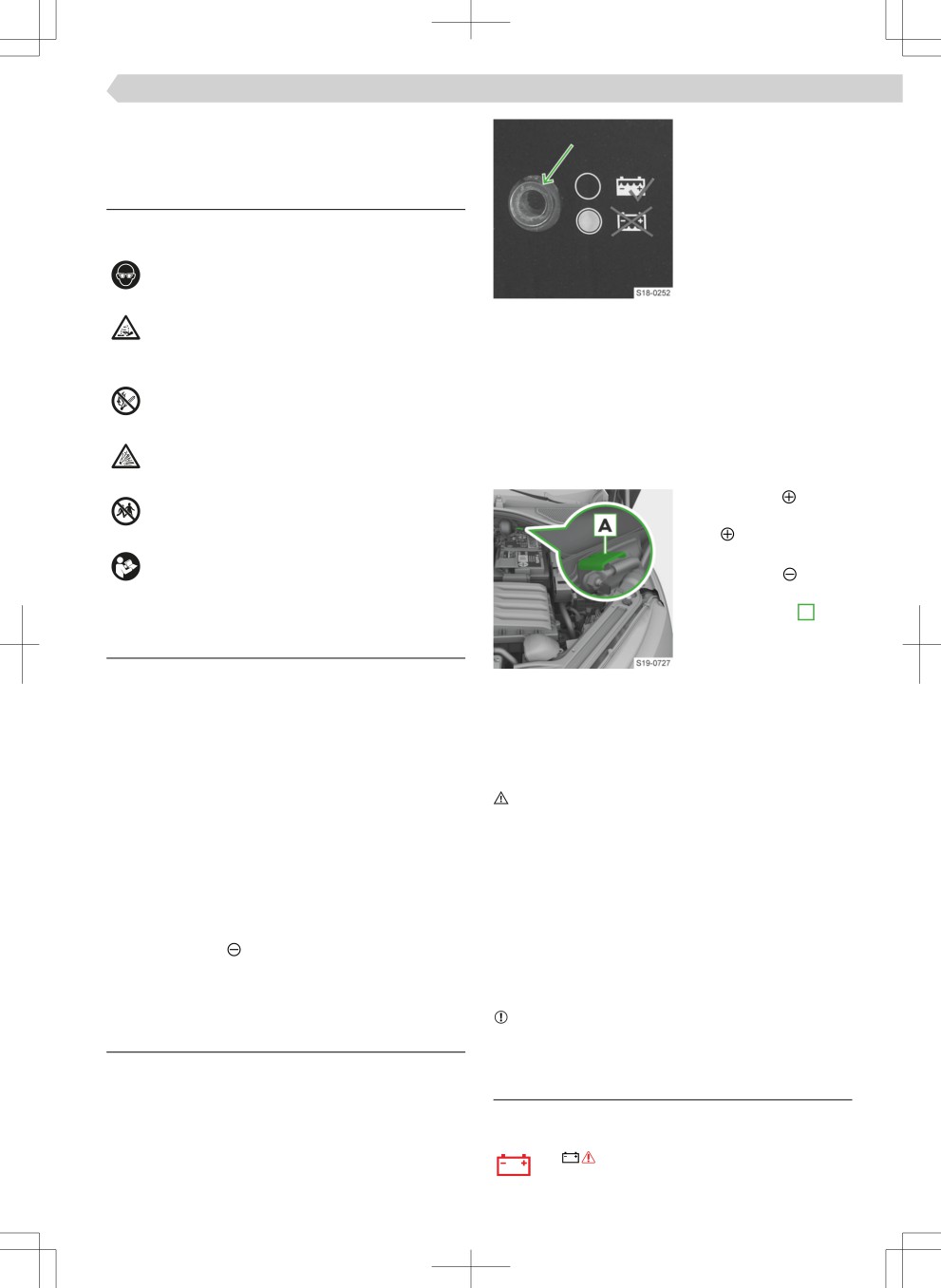
› Tap on the indicator
before testing, to clear
12 volt vehicle battery
air bubbles.
▶ Black colour - the acid
What you should be mindful of
level is OK.
Explanation of the warning symbols on the 12-volt
▶ Colourless or pale yel-
vehicle battery
low colour - acid level
is too low, the 12 volt
Wear safety goggles!
vehicle battery must
be replaced.
The battery acid of the 12-volt vehicle bat-
Requirements for charging a 12 volt vehicle bat-
tery is very caustic. Wear gloves and eye pro-
tery
tection.
✓ Ignition off
✓ Power consumers switched off
Keep fiÙe, sparks and open light away from
the 12 volt vehicle battery! Do not smoke!
12 volt vehicle battery charging
To charge the 12 volt vehicle battery fully, set a
When charging the 12 volt vehicle battery, a
charging current of max. of 0.1 times the battery ca-
highly explosive gas mixture is produced!
pacity.
› Connect the termi-
Keep children away from the 12 volt vehicle
nal of the charger to
battery!
the terminal of the
12 volt vehicle battery.
Refer to the owner’s manual!
› Connect the termi-
nal of the charger to
the earth point A .
Functionality - Protection against discharge of
› Plug the charger's
the 12 volt vehicle battery
power cable into the
socket and switch on
Possible causes for the discharge of the 12 volt
Earth point
the device.
vehicle battery
▶ Worn 12 volt vehicle battery
› After charging, switch off the charger and unplug
the power cable from the socket.
▶ Frequent short journeys
› Disconnect the charger terminals from the 12 volt
▶ Low temperatures
vehicle battery.
▶ Vehicle stationary for a long period of time
WARNING
Automatic system-related discharge protection
Risk of explosion!
measure with regard to the 12 volt vehicle battery
▶ During charging, hydrogen is released. An explo-
▶ Increasing the engine idling speed
sion can also be caused by sparks, for example,
▶ Switching off certain consumers or limiting their
when disconnecting or loosening the cable con-
power
nector.
Recommended measure to be taken when vehicle
▶ Never charge a frozen or thawed 12 volt vehicle
is stationary for more than three weeks
battery.
› Disconnect the terminal of the 12 volt vehicle
▶ Do not carry out the so-called quick charging of
battery.
the 12 volt vehicle battery yourself, but have it car-
ried out by a specialist garage.
Checking and charging the 12 volt vehicle
NOTICE
A Ĕat 12 volt vehicle battery can freeze easily!
battery
Checking the condition
The condition of the 12 volt vehicle battery is
Troubleshooting
checked by a specialist garage during servicing.
The 12 volt vehicle battery does not charge while
Checking the acid level
the engine is running
Applies to a 12 volt vehicle battery with an acid level
or
illuminates
indicator.
› Seek the help of a specialist garage.
186 12 volt vehicle battery and fuses › Using the jump-starting cable
Low charge level of the 48 volt battery
What you should be mindful of
Applies toe-TEC-vehicles.
WARNING
or
illuminates
Risk of explosion and chemical burns!
› Keep the engine turned on, but do not drive
▶ Do not jump start with the 12 volt vehicle battery
off.
of another vehicle under the following conditions:
› Stop with the vehicle on the spot until the indica-
▶ The discharged 12 volt vehicle battery is fro-
tor light goes out.
zen. A discharged 12 volt vehicle battery may
already freeze at temperatures just below 0 °C.
Engine fault
▶ The acid level of the 12-volt vehicle battery is
or
illuminates
too low » page 185.
› Stop driving!
Use jump leads with a suffiieÄt cross section and in-
› Stop the engine and seek the help of a specialist
sulated terminal clamps.
garage.
The rated voltage of both batteries must be 12V. The
capacity (in Ah) of the 12 volt charging vehicle bat-
tery must not be si£ÄifiaÄtlû lower than the capaci-
Disconnecting, connecting and replacing
ty of the discharged 12 volt vehicle battery.
CAUTION
Risk of fiÙe!
Use another vehicle's 12 volt vehicle battery
▶ Do not mix up the connection cables.
to operate the vehicle
Disconnecting
WARNING
› Close the electric boot lid, the tilting/sliding sun-
roof, all windows and the electric sunblind.
Risk of injury! Danger of damage to vehicle!
▶ Lay the jump start cables so that they cannot be-
› Switch off the ignition and any connected power
come caught by rotating parts in the engine com-
consumers.
partment.
› Disconnect the terminal and then the termi-
NOTICE
nal.
Short circuit!
Connecting
▶ The non-insulated parts of the terminal clamps
› Connect the terminal and then the terminal.
must not touch each other.
After switching on the ignition, the indicator lights
▶ The cable connected to the positive pole of the 12
light up
from the isolation box.
volt vehicle battery must not come into contact
with electrically conductive vehicle parts.
› If, after a short distance, one of the above-men-
tioned indicator lights does not go out, seek the
▶ The vehicles must not touch each other.
help of a specialist garage.
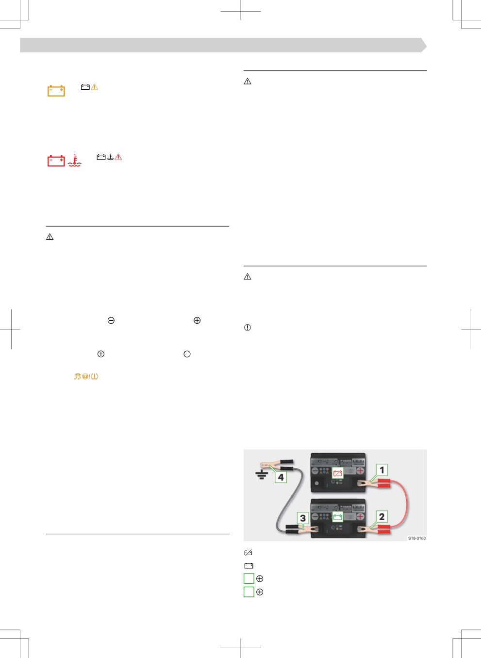
Connect the jump start cable
Operate these vehicle functions after disconnect-
› Switch off the ignition.
ing and connecting the 12 volt vehicle battery
› Connect the terminal clamps of the jump start ca-
▶ Window operation » page 29.
bles in the order shown in the legend.
Changing
The new 12 volt vehicle battery must have the same
parameters as the original battery. Have the replace-
ment carried out by a specialist garage.
Using the jump-starting cable
Usage
With the help of jump start cables, a vehicle with a
discharged or defective 12-volt vehicle battery can
discharged 12 volt vehicle battery
be started using the 12-volt vehicle battery of an-
current-supplying 12 volt vehicle battery
other vehicle.
1
-pole of the discharged 12-volt vehicle battery
2
-pole of the current-supplying 12 volt vehicle
battery
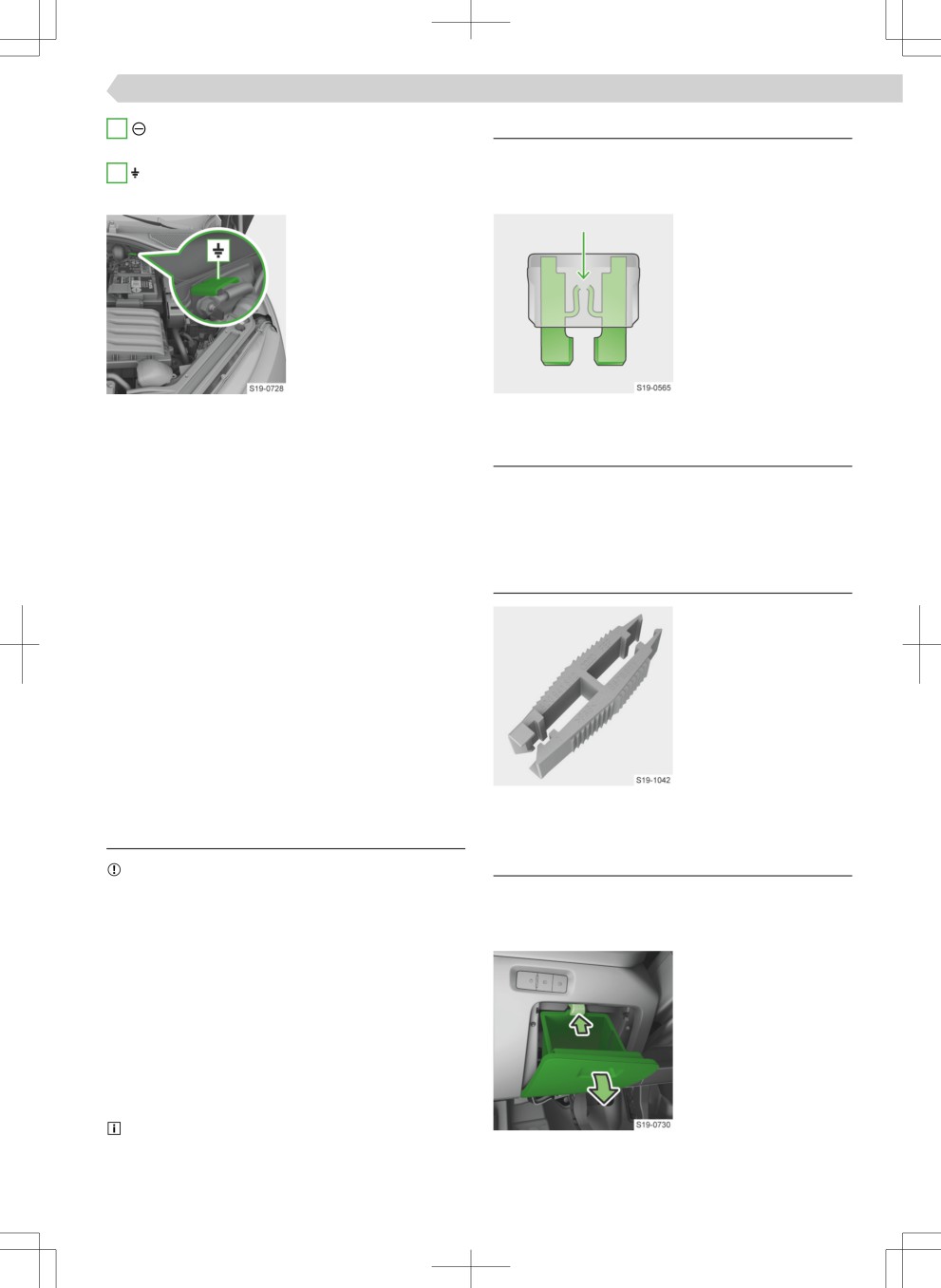
12 volt vehicle battery and fuses › Fuses 187
3
-pole of the current-supplying 12 volt vehicle
Functionality
battery (or earth point)
Fuses protect the vehicle systems from damage
4
Earth point of the vehicle with discharged 12
caused by excessive current. The fuse blows when
volt vehicle battery
the current is exceeded.
Earth point
Blown fuse
Start the engine
› Start the engine of the current-giving vehicle and
Conditions for replacing a fuse
let it idle (applies to vehicles with combustion en-
gine)
✓ Ignition off
Or:
✓ Driver door opened
› Switch on the electric drive of the vehicle supply-
✓ All consumers switched off
ing power (applies to vehicles with an electric mo-
tor).
Replacing a fuse
› Start up the vehicle with the discharged 12 volt
vehicle battery.
› Replace the fuse with
› If the engine of the vehicle with the discharged 12
the clip located under
volt vehicle battery does not start within 10 sec-
the cover of the fuse
onds, repeat the starting procedure after approxi-
box in the engine com-
mately 30 seconds.
partment.
Disconnecting the cable
› Use the appropriate
end of the clamp ac-
› Disconnect the cables in the reverse order from
cording to the fuse di-
connection.
mensions.
Fuses
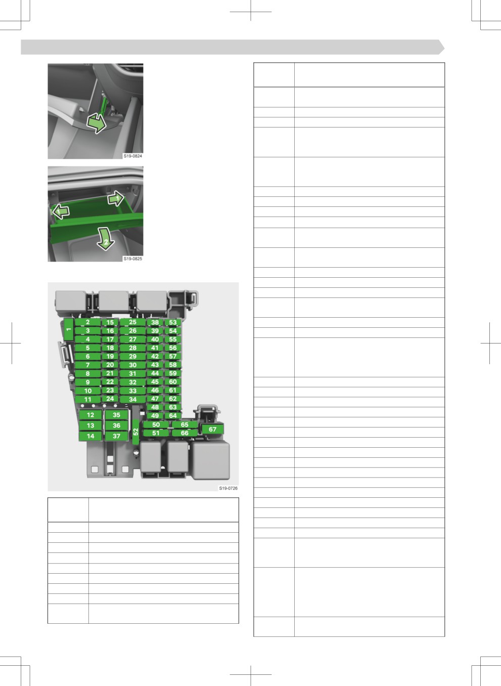
Fuses in the dash panel
What you should be mindful of
NOTICE
Overview
Fire hazard and risk of damage to the electrical sys-
Access to fuses - left-hand drive
tem.
› Open the storage compartment on the driver's
▶ Do not repair fuses or replace them with stronger
side.
fuses.
› Press the button and
▶ Replace the defective fuse with a new fuse with
open the tray.
the same amperage.
› Change the fuse.
▶ We recommend using replacement fuses from the
› Close the storage
ŠKODA Genuine Accessories range. These guaran-
compartment.
tee reliable and safe protection of the vehicle’s
electric system.
▶ If a newly inserted fuse blows again, seek the help
of a specialist garage.
One fuse may belong to several consumers. One
consumer may have several fuses.
Access to fuses - right-hand drive
› Open the storage compartment on the passenger's
side.
188 12 volt vehicle battery and fuses › Fuses in the dash panel
› Loosen the brake rod
Fuse
Consumer
of the storage com-
number
partment.
(Heating, fold-in function, setting the
mirror surface)
10
Not used
11
Tow hitch
12
Exterior vehicle lighting, fog lights on
the right, raised brake lights, license
plate lights
13
Central locking (rear doors and boot lid,
› Press the locking lugs,
fuel filleÙ Ĕap), windscreen washer sys-
the storage compart-
tem, headlight cleaning system
ment folds down.
14
Music amplifieÙ
› Change the fuse.
15
Not used
› Insert and lock the
16
Airbags
brake rod.
17
SCR (AdBlue®)
› Close the storage
18
Steering column lock, KESSY (keyless
compartment.
locking system)
19
Instrument cluster, emergency call, on-
line services
Fuses overview
20
Phonebox, USB connections
21
Rear view camera, Top View
22
Seat ventilation at the front
23
Interior lighting in front, microphone,
operation of the sliding/tilting sunroof
24
All-wheel drive
25
Belt tensioner - front left
26
Central locking + window lifter (right
side of the vehicle), right, exterior mir-
rors (Heating, fold-in function, setting
the mirror surface)
27
Belt tensioner - front right
28
Not used
29
Tow hitch
30
Infotainment
31
Tow hitch
32
Seat heating - rear
33
Not used
34
230 volt socket
35
Vehicle exterior lighting, left fog light
36
Air conditioning
37
Electric boot lid
38
Not used
Fuse
Consumer
39
Heated steering wheel
number
40
Not used
41
Databus
1
Not used
42
Automatic transmission, gear display
2
Not used
43
Front air conditioning, rear air condition-
3
Tow hitch
ing, auxiliary heater (auxiliary heating),
4
SCR (AdBlue
®)
rear window heating
5
Selector lever (automatic transmission)
44
Lane change assist system (Side Assist),
6
Interior lighting
diagnostic connection, rain and light
7
Heating of the front seats
sensor, automatic headlamp levelling,
8
Sliding/tilting roof
parking brake, alarm system, light
9
Central locking + window lifter (left side
switch, buttons in the centre console
of the vehicle), left, exterior mirrors
45
Steering column electronics, control
lever under steering wheel
12 volt vehicle battery and fuses › Fuses in the engine compartment 189
Fuse
Consumer
Fuses overview
number
46
Infotainment screen, Head-up display
47
Adaptive Chassis Control (DCC)
48
Not used
49
Not used
50
Not used
51
Not used
52
12 volt socket in the luggage compart-
ment
53
Non-contact operation of boot lid
54
Not used
55
Not used
56
Not used
Fuse
57
Not used
Consumer
58
Parking assistance, Park Assist, front ra-
number
dar sensor, front camera for assistance
Power steering
systems
1
The fuse can only be changed by a spe-
59
Parking brake, air conditioning, reverse
cialist company!
gear sensor, interior rearview mirror, en-
Assistance system ESC, engine control
2
gine sound generator
system, engine components
60
Diagnostic connection
Ignition, natural gas drive (applies to G-
3
61
Clutch pedal switch, engine start
TEC-vehicles)
62
USB rear, USB on interior rearview mir-
4
Left headlight
ror
5
Right headlight
63
Not used
6
Alarm system
64
Not used
7
Automatic gearbox
65
Not used
8
Brake servo
66
Rear window wiper
9
Horn
67
Heated rear window
10
Windscreen wiper
11
Not used
12
Automatic gearbox
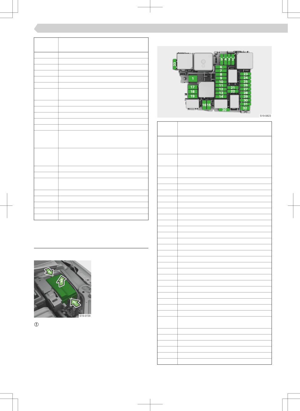
Fuses in the engine compartment
13
Assistance system ESC
14
Auxiliary heating
Overview
15
Assistance system ESC
16
Not used
Access to the fuses
17
Heating
› Simultaneously press
18
Heating
the locking buttons on
19
Not used
the fuse box cover and
20
Front diffeÙeÄtial lock (VAQ)
remove the cover.
21
Engine control system
› Change the fuse.
22
Starter
› Fit the cover and click
23
Engine control system
into place.
24
Engine components
25
Engine components
26
Engine components
Lambda sensors, particle filteÙ, NOx sen-
27
NOTICE
sor
Danger of water entering the fuse box.
28
Engine components
▶ Fit the cover correctly and click into place secure-
29
Fuel pump
ly.
30
Not used
31
Not used
32
Heated windscreen
33
Heating
190 Wheels › Tyres and rims
92 Load index
Wheels
H Speed symbol
Tyres and rims
Load index
The load index indicates the maximum permissible
What you should be mindful of
load for each individual tyre.
NOTICE
88
560 kg
▶ Protect tyres from contact with lubricants and
89
580 kg
fuel.
90
600 kg
▶ Always store wheels or tyres in a cool, dry and,
91
615 kg
where possible, dark place. Tyres without rims
92
630 kg
should be stored in an upright position.
93
650 kg
▶ Alloy rims can be damaged by grit.
94
670 kg
▶ Do not use light alloy rims with a high-sheen sur-
95
690 kg
face in wintry weather conditions or with snow
Speed symbol
chains
The speed symbol indicates the maximum permissi-
Causes of uneven tyre wear
ble speed for a vehicle fitted with tyres in the cate-
gory concerned.
▶ Improper tyre pressure.
▶ Driving style (e.g. fast cornering, rapid acceleration
S
180 km/h
and deceleration).
T
190 km/h
▶ Wheel alignment errors.
U
200 km/h
H
210 km/h
▶ Incorrect wheel balancing.
V
240 km/h
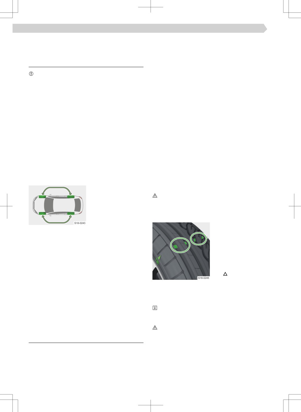
Wheel changes
W
270 km/h
For uniform wear on all
Y
300 km/h
tyres, we recommend
WARNING
that you change the
▶ Do not exceed the maximum permissible load and
wheels every 10,000 km
speed for the mounted tires.
according to the sched-
ule.
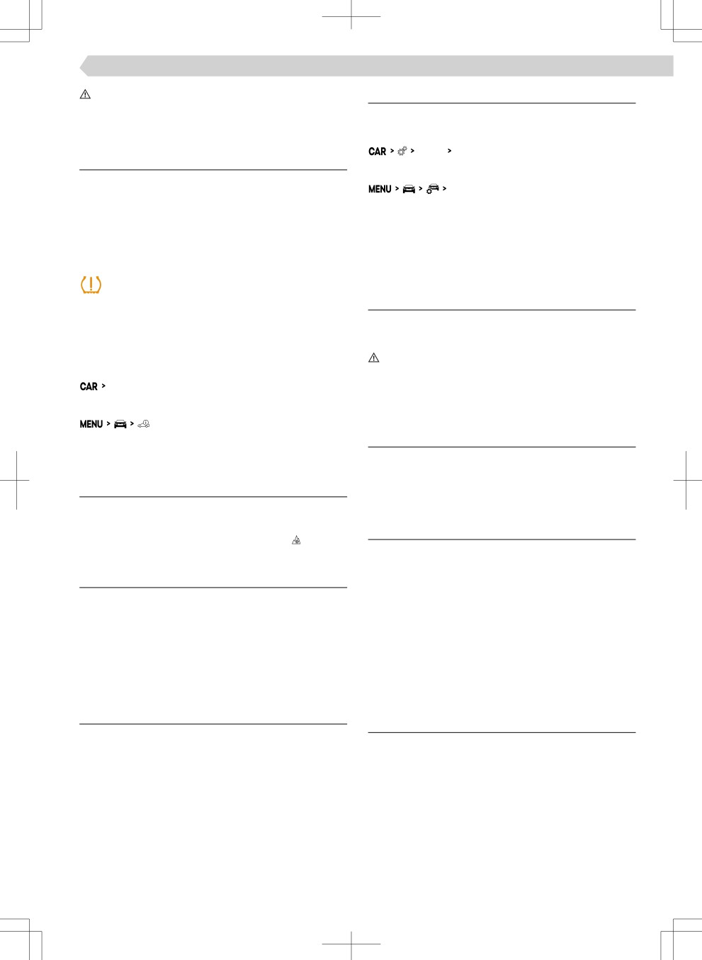
Tread wear indicators
Wear indicators are loca-
Advice for tyre assembly
ted in the pÙofile of the
› With directional tires, the correct direction of rota-
tyres that display the
tion must be observed. The direction of rotation of
permissible minimum
the tyres is marked by arrows on the wall of the
tread depth.
tyre.
Markings on the walls of
› Always replace the tyres by the axle.
the tyres with the letters
TWI or other symbols
Additional information
(e.g.
) indicate the po-
Only fit radial tyres of the same type, size (rolling cir-
sition of the wear indica-
cumference) and the same tread pattern on one axle.
tors.
Approved tyre sizes are speified in the technical ve-
A tyre is to be regarded as worn out when this wear
hicle documentation and in the declaration of con-
indicator is Ĕush with the tread.
formity (in the so-called COC Document).
The tread depth can be measured with a tread
The declaration of conformity can be obtained from
depth gauge on the ice scraper. The ice scraper is lo-
a ŠKODA Partner (valid for some countries and some
cated on the inside of the fuel filleÙ Ĕap.
models).
WARNING
Risk of accident!
Overview of tyre labelling
▶ Do not use worn tires.
Explanation of tyre markings
Tyre manufacturing date
e.g. 205/60 R 16 92 H
The date of manufacture is indicated on the tyre
sidewall.
205 Tyre width in mm
60 Height/width ratio in %
For example, DOT ... 18 20 means that the tyres
R Code letter for the type of tyre - Radial
were produced in the 18th week of the year 2020.
16
Diameter of wheel in inches
Wheels › All-season or winter tires 191
WARNING
Settings
Risk of an accident!
The speed limit setting for tyres is set in the Infotain-
▶ Do not use tyres that are older than 6 years.
ment in the following menu item:
Outside Tyres
Troubleshooting
Or:
Help with a Ĕat tyre
Outside
▶ Spare and emergency spare wheel » page 191
›
By moving your fiģe٠sideways, choose the screen
▶ Changing the wheel and raising the vehi-
with the menu item Tyres .
cle » page 192
›
Select Tyres - select them and set the speed limit.
▶ Breakdown kit » page 194
Change of tyre pressure
illuminates
Snow chains
› Stop the vehicle.
Usage
› Check the tyres and tyre pressures.
The snow chains improve driving in wintry road con-
Show tyres with modified pressure
ditions.
› In the following menu, select the menu item for
WARNING
displaying the tyre condition:
Risk of accident as well as tyre damage!
Tyres
▶ Do not use chains on routes that are free from
snow and ice.
Or:
What you should be mindful of
All-season or winter tires
› Before fittiÄ£ the snow chains, remove the full
wheel trims.
Usage
› Only mount the snow chains on the front wheels.
All-season or winter tyres improve handling in winter
weather conditions. They are characterised by ‘M+S’
Technical data
and a mountaintop and sÄoõĔake symbol
Permitted rim/tyre combinations for mounting of
snow chains:
What you should be mindful of
Rim size
Tyre size
For the best possible handling, use tyres on all four
6.5Jx16 ET46
205/60 R16
wheels with a minimum tread depth of 4 mm.
6.5Jx17 ET46
205/55 R17
Change winter tyres to summer tyres at the appro-
priate time. Summer tyres have better driving and
Only fit snow chains with links and locks that are no
braking characteristics on snow- and ice-free roads
larger than 9 mm.
and at temperatures above 7 °C.
Spare and emergency spare wheel
Usage conditions
Overview
If all-season or winter tyres are installed that have a
Spare wheel
lower speed category than the actual speified maxi-
▶ The dimensions of a standard spare wheel corre-
mum vehicle speed, then proceed as follows:
spond to the dimensions of the wheels mounted
› In Infotainment, set the speed limit according to
on the vehicle.
the category of tyres fitted.
▶ A temporary spare wheel is provided with a warn-
› In the driver's field of view, affix a warning label
ing label on the rim. This wheel is intended to ena-
with the maximum value of the speed category in-
ble you to reach the nearest specialist garage.
tended for the tyres fitted (applies only to certain
IÄĔate a space saver wheel with the maximum pre-
countries).
scribed pressure.
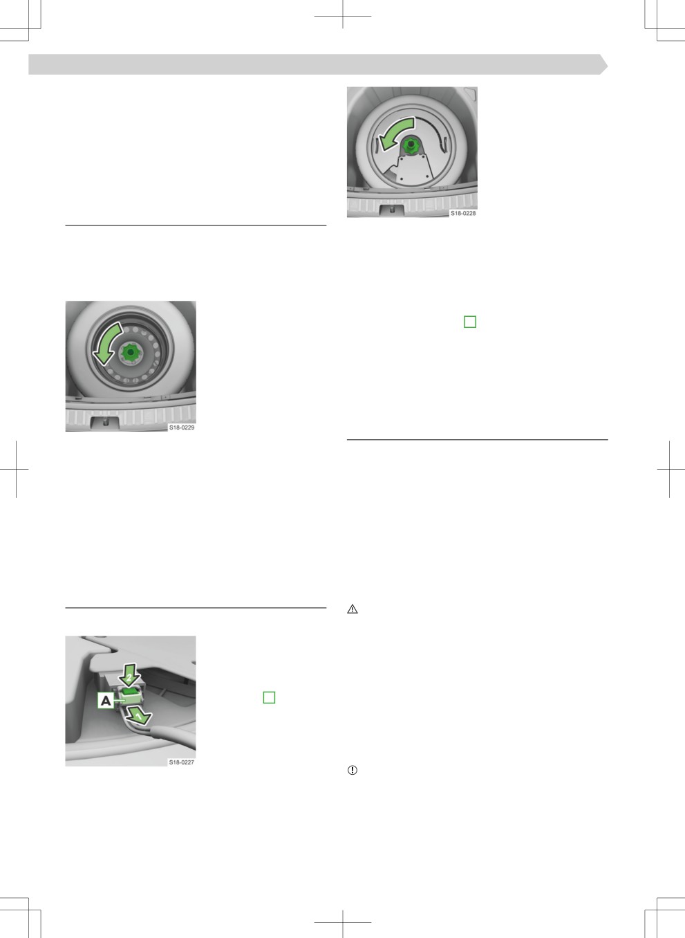
192 Wheels › Changing the wheel and raising the vehicle
Emergency wheel
› Unscrew the lock nut.
A warning label is displayed on the rim of the tempo-
› Remove the bass loud-
rary spare wheel. This wheel is intended to enable
speaker.
you to reach the nearest specialist garage.
› Take out the wheel.
An emergency wheel is si£ÄifiaÄtlû narrower than
the wheels mounted ex-factory.
Remove the wheel on vehicles without sound
system and replace
Inserting
The spare wheel or emergency wheel is mounted in a
› Insert the wheel into the wheel well with the out-
recess under the ĔooÙ covering or the variable load-
side facing downwards.
ing ĔooÙ in the boot.
› Insert the bass loudspeaker.
Removing
› Screw in the locknut until it stops.
› Loosen the retaining
› Insert the connector in the bass loudspeaker.
belt and take out the
› Secure the safety tab A .
box with the tool kit.
› Place the box with the tool kit and secure it with
› Unscrew the lock nut.
the tape.
› Take out the wheel.
Changing the wheel and raising the
vehicle
What you should be mindful of
Inserting
Before changing
› Insert the wheel into the wheel well with the out-
› Park the vehicle securely and secure it from rolling
side facing downwards.
away.
› Pull the fixiÄ£ band through the opposite holes in
› Turn off the engine.
the wheel rim.
› Let all of the occupants get out. During the wheel
› Screw in the locknut until it stops.
change they should not stand on the road, e.g. be-
› Replace the box with the tool kit into the wheel
hind the crash barriers.
and secure it with the tape.
› Close all doors, the boot and bonnet.
› Uncouple any trailers.
Remove the wheel on vehicles with sound
Raise vehicle
system and replace
WARNING
Removing
Always ensure the base plate of the lifting jack can-
not slip!
› Loosen the retaining
▶ Provide a wide and fiÙm base under the jack on
belt and take out the
loose surfaces.
box with the tool kit.
▶ Create a non-slip base (e.g. a rubber ĔooÙ mat) un-
› Partially pull out the
der the jack on a smooth surface.
safety tab A .
▶ Always raise the vehicle with the doors closed.
› Press the safety button
▶ Do not insert any body parts under the raised vehi-
and remove the plug.
cle.
▶ Do not start the engine of the lifted vehicle.
NOTICE
Danger of damage to vehicle!
▶ Make sure that the jack is attached correctly to the
bridge of the sill.
After having been changed
› Check the tyre pressure on the mounted wheel
and adjust if necessary.
Wheels › Changing the wheel and raising the vehicle
193
› In vehicles with a tyre indicator, save the tyre pres-
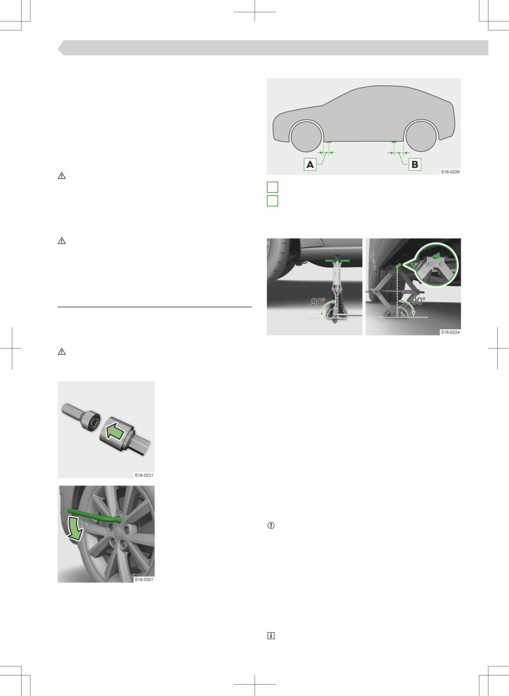
Jacking points for the jack
sure values in the system.
› Have the tightening torque of the wheel bolts of
the mounted tyres checked with a torque wrench
as soon as possible.
The speified tightening torque is 140 Nm.
Drive carefully until the tightening torque is checked.
Replace the damaged tyre. It is not recommended to
repair the tyre.
WARNING
Risk of an accident!
A
18 cm
▶ Too low a tightening torque may cause the wheel
B
30 cm
to disengage while driving.
▶ Too high a tightening torque can damage the
Position the jack and lift the vehicle
threads and cause the rim to deform.
Use the jack from the tool kit.
WARNING
Risk of an accident!
▶ Do not grease or lubricate screws.
▶ Do not use corroded or damaged screws.
Changing the wheel and raising the vehicle
Release screws
› If the vehicle has covers over the wheel bolts or
wheel trims, remove them.
› Position the jack at the jacking point closest to the
WARNING
wheel to be replaced.
▶ If you step on the key end when loosening the
› Support the base plate of the jack with its full area
screw, hold on to the vehicle for better stability.
resting on level ground and ensure that the jack is
Some vehicles may have
located in a vertical position at the jacking point.
anti-theft wheel bolts
› Use the crank to raise the jack until its claw enclo-
that protect the wheels
ses the bar.
from theft.
› Continue to lift the vehicle until the wheel is just
› Insert the upper sec-
off the ĔooÙ.
tion on the anti-theft
wheel bolt until it
Changing a wheel
stops.
› Unscrew the screws and place them on a clean
surface.
› Remove the wheel carefully.
› Place the key on the
› Attach the wheel.
wheel bolt or on the
› Slightly screw in the screws.
attachment piece.
› Lower the vehicle.
› Turn the screw a maxi-
NOTICE
mum of half a turn so
▶ Applies to wheel trims supplied ex-factory or from
that the wheel does
ŠKODA Original Accessories: the anti-theft wheel
not come loose and fall
bolt should be installed in the position marked on
off.
the back of the wheel trim.
Tighten screws
› Tighten the opposite wheel bolts including the an-
ti-theft wheel bolt one after the other.
› Reinstall the cover caps of the wheel bolts or the
full wheel covers.
Keep the label with the code number of the anti-
theft wheel bolts. A replacement upper section can
194 Wheels › Breakdown kit
be acquired from ŠKODA original parts based on
› Close all doors as well as the bonnet and boot lid.
this.
› Uncouple any trailers.
After using the kit
If a tyre pressure of 2.0 bar cannot be achieved, the
Breakdown kit
tyre is too damaged and cannot be sealed with the
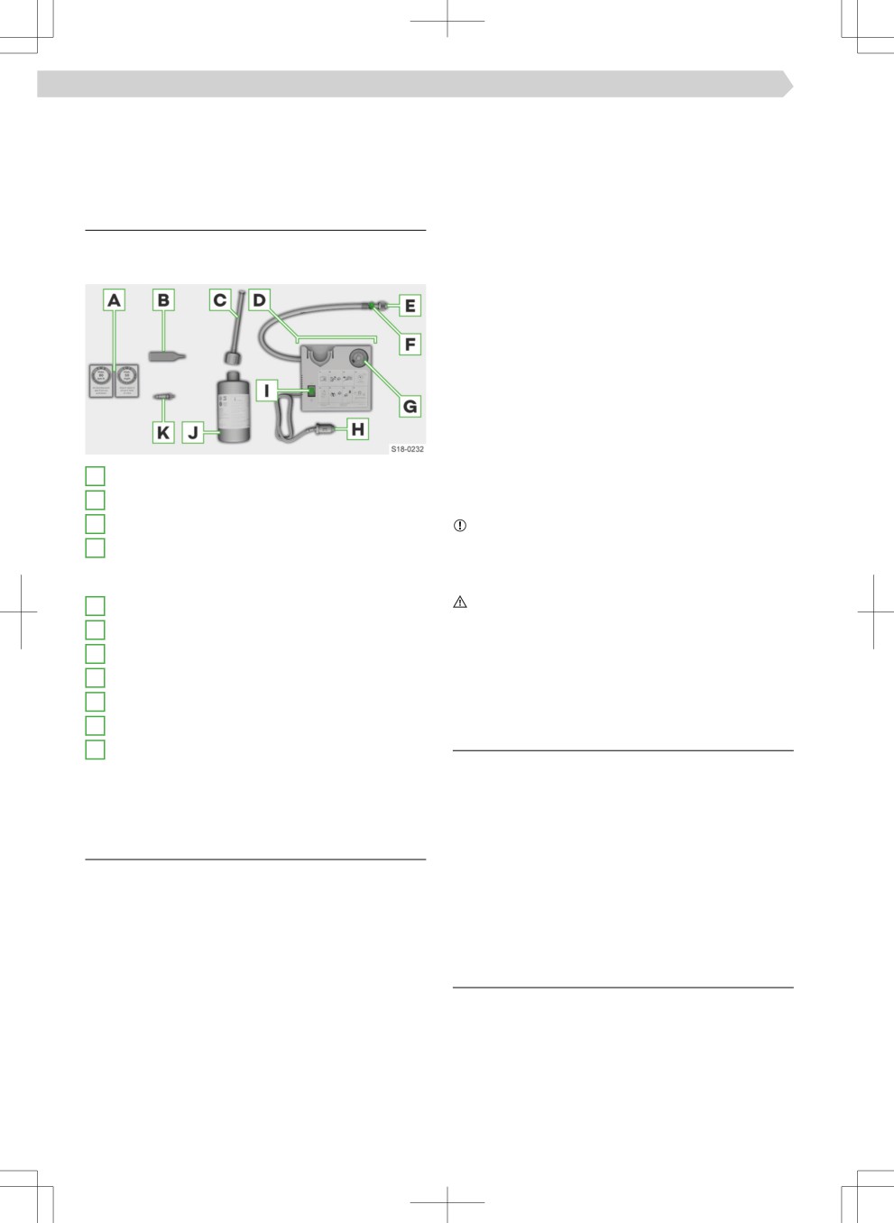
Content overview
puncture set.
› Stop driving. Seek the help of a specialist garage.
The kit is located in a box under the ĔooÙ covering in
the luggage compartment.
Once a tyre pressure of 2.0-2.5 bar is achieved, con-
tinue the journey at a maximum speed of 80 km/h
(50 mph).
› Avoid full accelerations, strong braking and fast
cornering.
Information for driving with repaired tyres
›
The pressure of the repaired tyre must be checked
after driving for 10 minutes.
› If the tyre pressure is 1.3 bar and less, do not con-
tinue! Seek the help of a specialist garage.
› If the tyre pressure is higher than 1.3 bar, correct
A
Sticker with speed indication
the pressure to the correct value of at least 2 bar
B
Valve remover
and continue driving.
C
IÄĔatioÄ hose with plug
NOTICE
Danger of damage to the compressor!
D
Air compressor (the layout of the controls may
be diffeÙeÄt depending on the type of air com-
▶ After the maximum running time of the air com-
pressor, allow it to cool for a few minutes.
pressor)
E
Tyre iÄĔatioÄ hose
WARNING
Risk of burns!
F
Button for pressure reduction
The tyre iÄĔatioÄ hose and the air compressor may
G
Pressure indicator
become hot when iÄĔated.
H
12 volt cable connector
▶ Allow the air compressor and hose to cool for a
few minutes.
I
ON and OFF switch
J
Tyre iÄĔatioÄ bottle
Usage restrictions
K
Replacement valve core
Do not use the kit in the following cases:
The declaration of conformity is included with the air
▶ The rim is damaged.
compressor or the log folder.
▶ The outdoor temperature is below the minimum
temperature indicated in the manual of the tyre fill-
Usage conditions
iģ bottle.
▶ Tyre punctures are greater than 4 mm.
Performing a repair with the breakdown kit not at all
▶ There is damage to the tyre wall.
intended to replace a permanent repair on the tyre.
▶
The expiry date stated on the tyre iÄĔatioÄ bottle
The purpose of the repair is to get you to the nearest
has expired.
specialist garage.
Change the tyre repaired by the breakdown kit as
soon as possible.
Self-help
Before using the kit
Seal the tyres
› Park the vehicle securely and secure it from rolling
› Unscrew the valve cap from the damaged tyre.
away.
› Unscrew the valve core with the valve insert and
› Turn off the engine.
place it on a clean surface.
› Let all of the occupants get out. During the wheel
› Shake the tyre iÄĔatioÄ bottle back and forth with
repair they should not stand on the road, e.g. be-
sealant.
hind the crash barriers.
Wheels › Tyre pressure 195
› Screw the iÄĔatioÄ hose onto the tyre iÄĔateÙ bot-
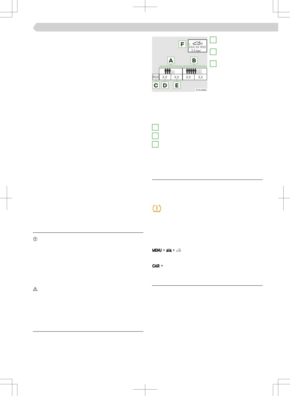
A
IÄĔatioÄ pressure for
tle. The film on the closure is pierced automatically.
half load
› Remove the plug from the iÄĔatioÄ hose and push
B
IÄĔatioÄ pressure for
it fully onto the tyre valve.
a full load
› Hold the bottle with the bottom facing upwards
C
Tyre diameter in in-
and fill all of the sealing agent into the tyre.
ches
› Remove the filleÙ plug from the valve.
This information only
› Screw in the valve insert.
serves as informa-
tion for the prescri-
IÄĔate tyres
bed tyre pressure.
› Fit the tyre iÄĔatioÄ hose of the air compressor to
This is not a listing of
the tyre valve.
approved tyre sizes for your vehicle. These are in
› Secure the vehicle with the parking brake.
the vehicle's technical documentation, as well as
› Start the engine.
in the declaration of conformity (in the so-called
› Plug the connector into the 12 volt socket .
COC document).
› Turn on the air compressor.
D
Tyre pressure reading for the front axle tyres
› Once a tyre pressure of 2.0-2.5 bar is reached, turn
E
Tyre pressure reading for the rear axle tyres
off the air compressor.
F
Prescribed tyre pressure value for the emergen-
Observe the maximum running time of the air com-
cy wheel
pressor according to the directions of the repair kit
manufacturer.
› If an air pressure of 2.0 - 2.5 bar has not been
Tyre pressure monitor
reached, remove the tyre iÄĔatioÄ hose from the
Functionality
valve.
› Drive approx. 10 metres forwards or backwards to
The tyre pressure monitoring indicator indicates a
allow the sealing agent to distribute in the tyre.
change in tyre pressure.
› Replace the tire iÄĔatioÄ hose on the valve and re-
Warning when pressure changes
peat the iÄĔatioÄ procedure.
illuminates
› Stop the vehicle.
Tyre pressure
› Check the tyres and tyre pressures.
What you should be mindful of
Show tyres with modified pressure
› In the following menu, select the menu item for
NOTICE
displaying the tyre condition:
▶ Always adjust the tyre pressure to the load.
▶ Check the pressure in all tyres at least once a
month and before each longer ride.
Or:
▶ Check the pressure when the tyres are cold. Do
Tyres
not reduce the higher pressure of warm tyres.
▶ After each change in tyre pressure, save the new
values in the tyre control display.
Function restriction
WARNING
The system is unable to provide a warning in the
Risk of an accident!
event of a very rapid tyre pressure loss, e.g. sudden
▶ If tyre pressure loss is very quick, try to stop the
puncture.
vehicle carefully without heavy steering or heavy
braking.
The system function may be restricted in the follow-
ing cases:
▶
Uneven loading of the wheels, e.g. with a trailer at-
Sticker with prescribed tyre pressures
tached
The sticker with prescribed tyre pressures is located
▶ Sporty driving style
on the inside of the fuel filleÙ Ĕap.
▶ Driving on dirt roads
▶ Snow chains fitted