Scania Instrumentation en-GB 2 374 015. Operator's manual - part 1
Operator's manual
Scania
Instrumentation
en-GB 2 374 015
Issue 2.0
Introduction
3
Overview
3
Analogue instrument panel
5
Analogue instrument panel for engines without
SCR system
5
Analogue instrument panel for engines with SCR
system
6
Display in tachometer
7
Control panel
10
Starter lock
10
Engine speed setting 1 and 2
11
Idling speed adjustment
12
Limp home mode
12
Remote control
13
Digital display
14
Function
14
Display structure
15
Favourite screens
16
Information (4)
19
Statistics trip (4.1)
19
Performance (4.2)
19
Fault codes (5)
21
Information about the highlighted fault code
22
Clear fault codes
22
Update the fault code list
23
Settings (6)
23
Contrast/brightness (6.1)
23
Button beep (6.2)
24
Language (6.3)
24
Units (6.4)
25
Engine (6.5)
26
Examples of setting
32
Base system (6.6)
33
Alarm and fault code generation
33
Alarms
33
External alarm signal
35
Fault code generation
35
2
Introduction
Introduction
This Operator's manual describes operation of
Scania instrumentation.
The information in this manual was correct at the
time of going to press. Scania reserves the right
to make alterations without prior notice.
Note:
Always use Scania spare parts for repair work.
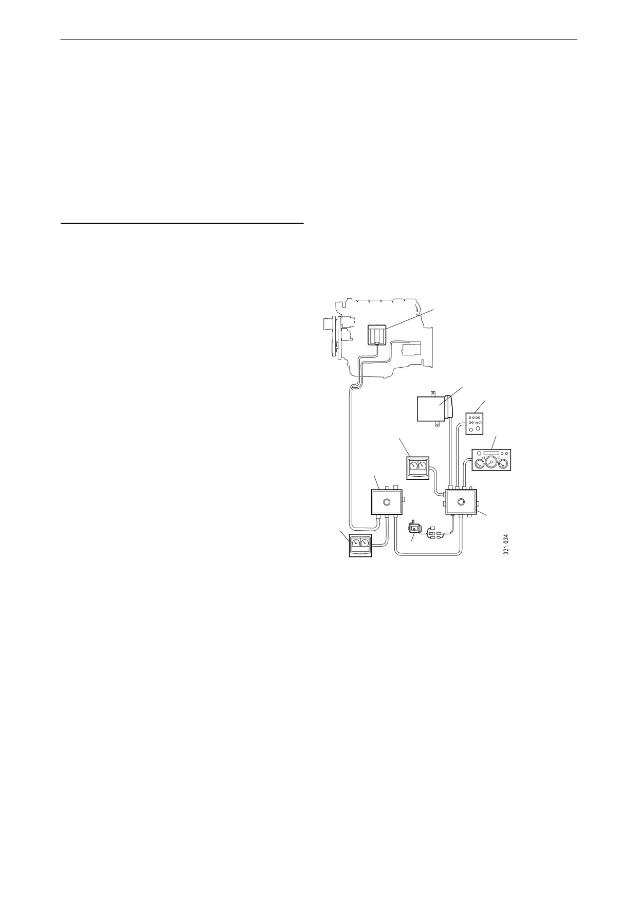
Overview
1
The base system consists of a coordinator, coor-
dinator junction box and main junction box. The
main junction box is connected directly to the en-
gine control unit. There are a number of different
options for the base system that can be connected
3
to the system:
6
• A digital display together with a control panel
with starter key.
7
4
• An analogue instrument panel that can be
used instead of the digital display or together
2
with it.
• An accelerator pedal sensor.
• A remote control (for marine engines only).
5
4
The entire instrumentation system is Plug and
Play which makes it very easy to install.
8
This Operator's manual only describes the ana-
Base system for industrial engines
logue instrument panel, remote control, digital
display and control panel.
1. Engine control unit
2. Main junction box
3. Coordinator
4. Digital display
5. Coordinator junction box
6. Control panel
7. Analogue instrument panel
8. Accelerator pedal sensor
3
Overview
1
8
7
2
6
9
3
5
4
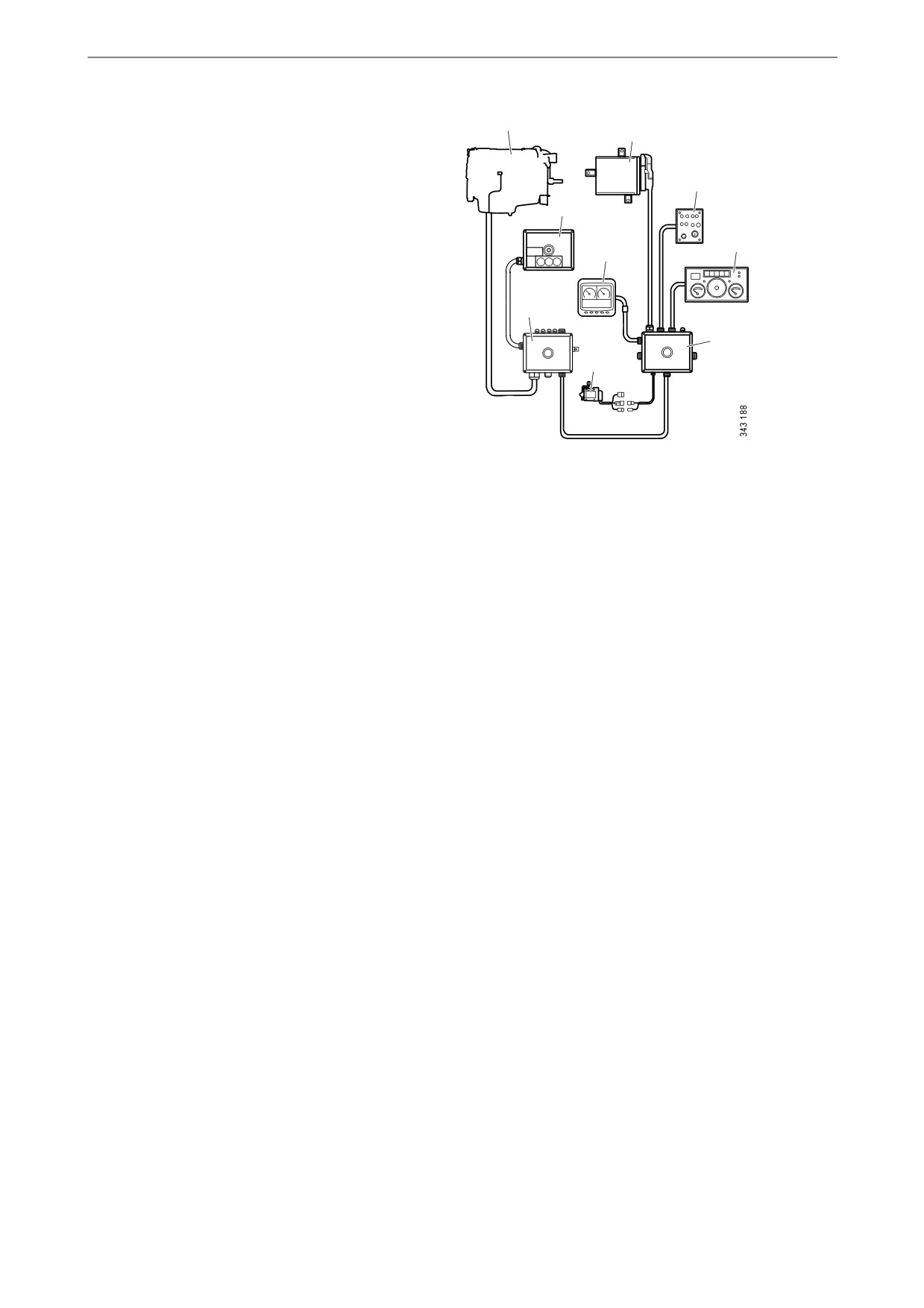
Base system for marine engines
1. Engine control unit
2. Remote control
3. Main junction box
4. Accelerator pedal sensor
5. Coordinator junction box
6. Analogue instrument panel
7. Control panel
8. Coordinator
9. Digital display
4

Analogue instrument panel
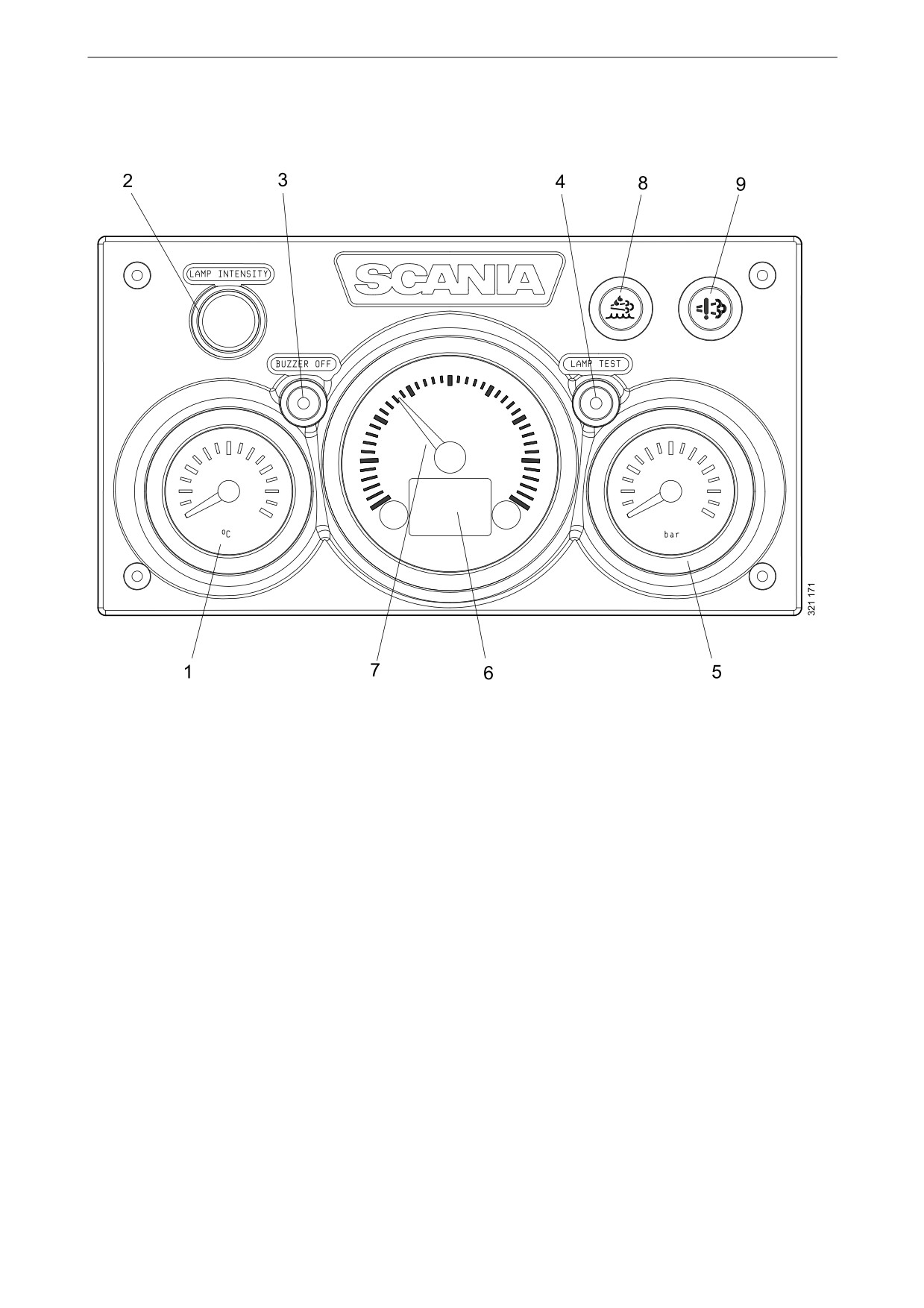
Analogue instrument panel
The analogue instrument panel has instruments
for reading engine speed, coolant temperature
and oil pressure. It also has hour counting and di-
agnostic and alarm switches and lamps.
The analogue instrument panel is available in 2
versions, depending on whether the engine is
equipped with an SCR system or not.
Analogue instrument panel
for engines without SCR sys-
tem
1. Coolant temperature display
2. Adjusting instrument lighting brightness (Lamp intensity)
3. Buzzer deactivation (Buzzer off)
4. Lamp test (Lamp test)
5. Display for oil pressure
6. Display showing engine data, alarms and fault codes
7. Tachometer
5
Analogue instrument panel
Analogue instrument panel
for engines with SCR system
1. Coolant temperature display
2. Adjusting instrument lighting brightness (Lamp intensity)
3. Buzzer deactivation (Buzzer off)
4. Lamp test (Lamp test)
5. Display for oil pressure
6. Display showing engine data, alarms and fault codes
7. Tachometer
8. Warning lamp for low reductant level
9. Warning lamp for SCR system faults.
6
Analogue instrument panel
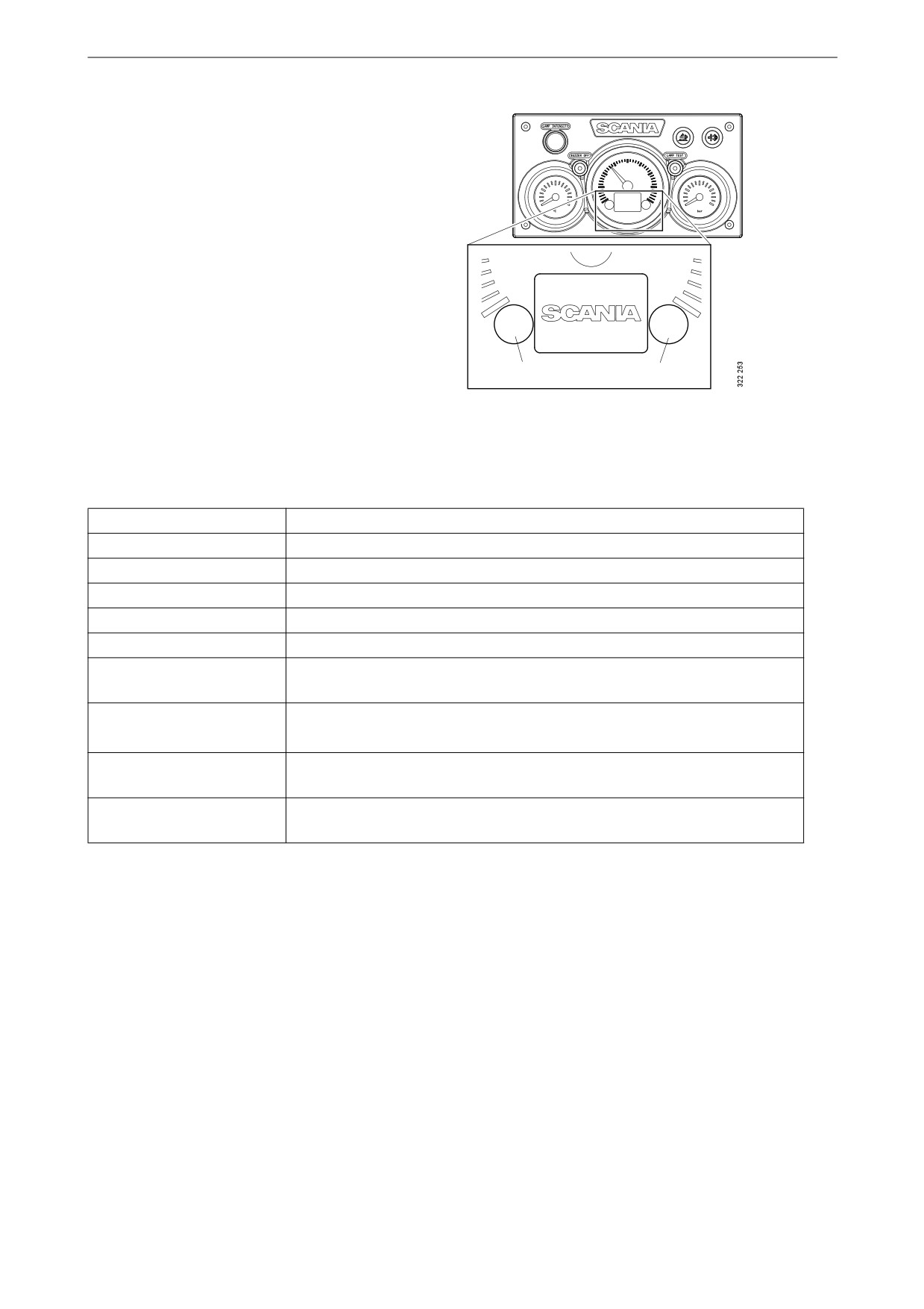
Display in tachometer
Integrated in the tachometer is a digital display
that shows engine data, alarms and fault codes.
Button 1 displays the previous page and button 2
displays the next page. The table below describes
how to go down a level in the structure.
1
2
Engine data shown on the display
Engine data
Explanation
Coolant temperature
Oil pressure
Fuel level
Fuel consumption
Charge air pressure
Reset the trip meter by holding buttons 1 and 2 down at the same time for
Trip meter
3 seconds.
Adjusting instrument light-
Reduce the brightness by holding button 1 down for 3 seconds
ing brightness
Increase the brightness by holding button 2 down for 3 seconds
Settings
No settings can be changed. The only available language is English and the
only available unit is metric
Fault codes
Display an explanation of active fault codes by holding buttons 1 and 2
down at the same time for 3 seconds.
7

Analogue instrument panel
Alarms
On the display in the tachometer, the following
alarms are shown:
Alarm
Symbol
High coolant temperature
Low oil pressure
Oil level too high or low1
Alternator not charging
Low reductant level1
SCR fault1
Low coolant level1
1. Depending on how the engine is equipped.
8

Analogue instrument panel
Fault codes
When a fault code is generated, a symbol is
shown on the display in the tachometer. Ac-
knowledge the fault code by pressing button 1 or
2.
1
2
Once the fault code has been acknowledged, the
fault code symbol remains (refer to illustration)
Coolant [C˚]
as long as the fault code is active.
92.2
Fault code description
If you want to see a more detailed description of
the fault code, hold buttons 1 and 2 down at the
same time for 3 seconds.
The fault code contains the following informa-
tion:
Pos
Information
Explanation
1
Shows the con-
The engine management
trol unit in
system (EMS), coordina-
which the fault
tor (COO) or SCR control
code was regis-
unit (SCR)
4
tered
2
Counter
Shows how many times
1
DTC:
2100!
the displayed fault has oc-
curred
2
EMS
5
3
Fault code sym-
11
bol
6
3
4
Fault code
Shows the fault code in
1/16
hexadecimal form
5
Active fault
! is shown if the fault code
code
is active. If the fault code
is inactive, no ! is dis-
played
6
Page
Shows which page is ac-
tive and how many pages
there are
9
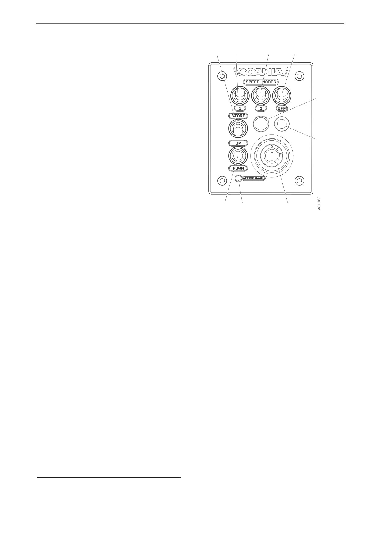
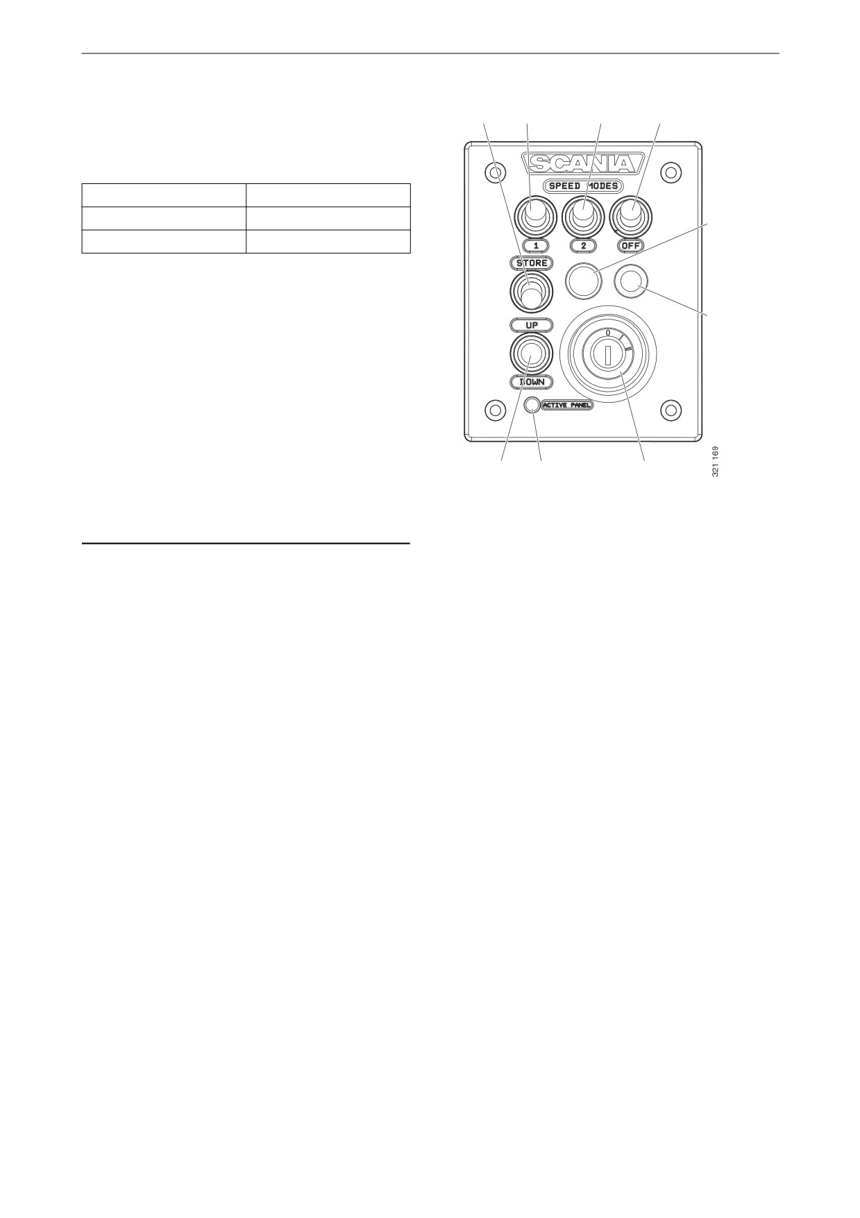
Control panel
Control panel
2
3
4
5
The engine is started and shut down from the
control panel, which has a starter lock and func-
tions for engine speed setting and idling setting.
1. Control for adjusting engine speed and idling
6
speed
2. Control for storing new engine speed and
idling speed
3. Control for activating engine speed setting 1
7
4. Control for activating engine speed setting 2
5. Control for deactivating engine speed setting
1 (marine engines) or 2 (industrial engines).
6. Indicator lamp for limp home throttle con-
trol1
7. Limp home throttle control (Limp home)1
8. Starter lock
9. Indicator lamp for active panel (Active pan-
1
9
8
el)
Starter lock
The starter lock (8) is used to start and shut down
the engine.
Position 0: The engine electrical system and the
engine are switched off.
Position 1: The engine electrical system is acti-
vated.
Position 2: The starter motor is activated.
1. Only available for marine engines.
10

Control panel
Engine speed setting 1 and 2
2
3
4
5
Engine speed setting 1 is an engine speed set be-
tween high and low idling. High and low idling
vary depending on the engine. The engine speed
is set with control 3.
6
Engine speed setting 2 is an engine speed that is
set between 450 and 2,000 rpm. The engine
speed is set with control 4.
For both engine speed settings, torque limitation
can be set via either the digital display or using
7
SDP3. The engine speed settings are isochro-
nous, i.e. the engine speed is held constant irre-
spective of load.
When either of the engine speed settings is acti-
vated, the engine speed goes up or down to the
last saved engine speed.
In order to activate engine speed setting 1 or 2,
1
9
8
the engine must be running, the active panel in-
dicator lamp must be on and the throttle must be
at 0%.
Change the engine speed:
• Activate engine speed setting 1 or 2 with con-
trol 3 or 4.
• Adjust engine speed up or down with control
1.
• Save the new setting by holding control 2
down for 3 seconds.
Note:
If the setting is not saved, the engine uses the last
saved value next time engine speed setting is ac-
tivated.
This is how to switch off the engine speed set-
tings:
• Press control 5, touch the accelerator pedal or
switch off the engine.
11
Control panel
Idling speed adjustment
2
3
4
5
Setting range:
Engine type
Setting range
XPI engine
600-750 rpm
6
PDE engine
500-1,300 rpm
Set the engine idling speed:
• Hold control 2 down for 3 seconds. This will
take you to the adjustment mode.
7
• Adjust idling up or down with control 3.
• Save the new setting by holding control 2
down for 3 seconds.
It is also possible to change engine idling speed
with the digital display or using SDP3.
Note:
1
9
8
In order to change the idling speed setting, the
coolant temperature must be higher than 50°C
(122°F) with the engine idling.
Limp home mode
Limp home mode is a marine engine function
that is activated if the coordinator or accelerator
pedal fails or if CAN communication is not
working.
If one of these occurs, the indicator lamp for limp
home throttle control 6 and limp home throttle
control 7 is connected.
The limp home throttle consists of a potentiome-
ter on the control panel which can be used to
limp home. The potentiometer value goes direct-
ly to connector A2 on the engine control unit.
In order to use the limp home throttle control, the
potentiometer must first be turned to the 0 posi-
tion and then activated.
12
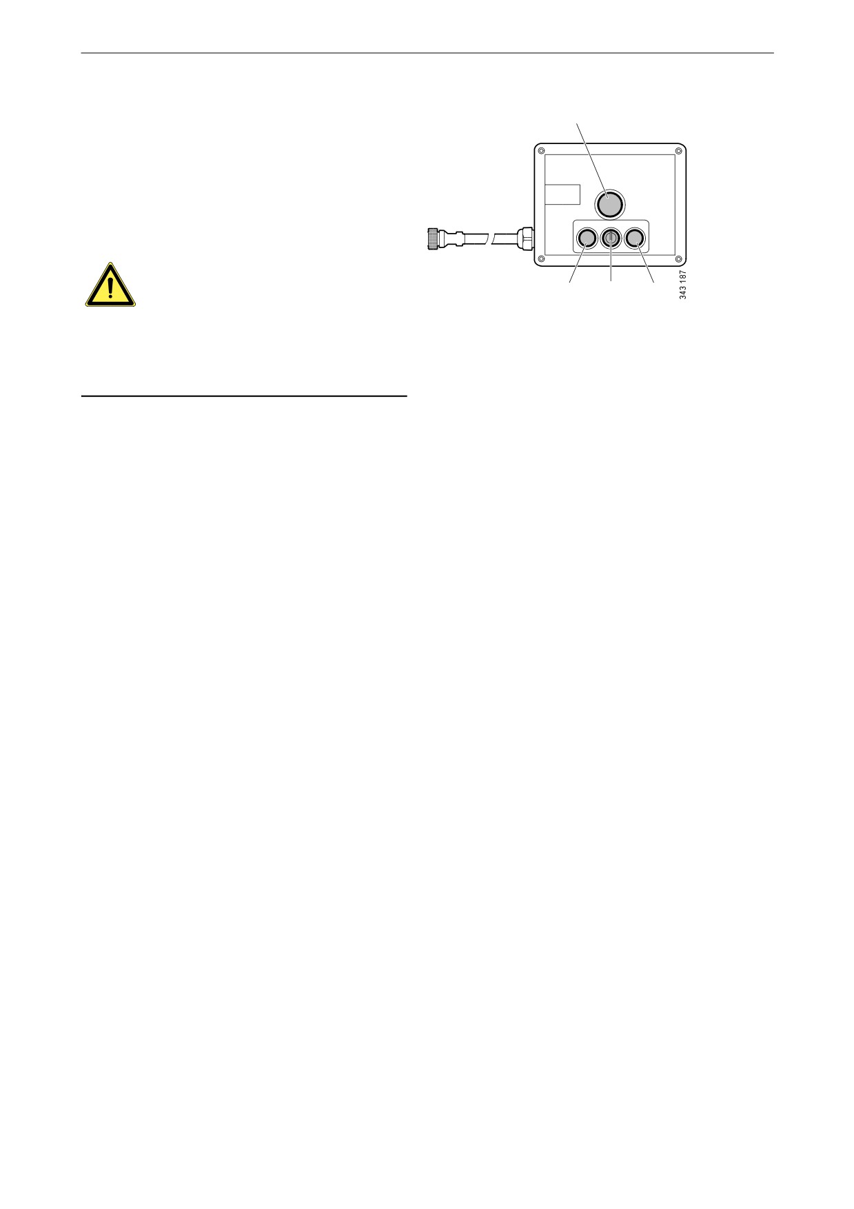
Remote control
Remote control
1
The remote control for marine engines is con-
nected on connector C4044 on the main junction
box. The remote control can be used to lock the
engine so that it cannot be controlled from any-
where other than where the remote control is lo-
START
LOCAL
REMOTE
STOP
cated.
WARNING!
2
3
4
This can and should only be done when the boat
Remote control
is moored, i.e. when there is no risk that the boat
1.
Green indicator lamp
will drift out of control. There is a sign on the re-
2.
Starter button
mote control with this warning text.
3.
Key switch to activate the Local function
4.
Stop button
There are 2 positions for key switch 3: Local and
Remote.
• Local: The engine cannot be controlled from
anywhere other than from the remote control.
• Remote: Normal position, i.e. the engine can
be operated from the other throttle control po-
sitions.
When Local mode is activated, the green indica-
tor lamp 1 comes on. At the same time the active
panel indicator lamp on the control panel starts to
flash, which indicates that the control panel can-
not be activated.
When the engine is started from the remote con-
trol via starter button 2, it only runs at idling
speed whileLocal mode is activated and no other
throttle control can be used.
If the key switch is reset from Local to Remote
when the engine is running, the green indicator
lamp 1 goes out and the engine continues to run
at idling speed. Other control positions can how-
ever take command of throttle control, if the con-
trol panel is activated. If key switch 3 is reset
from Remote to Local while running, nothing
happens, but this will be regarded as an uninten-
tional action.
If CAN communication fails when the engine
has been started from the remote control, the en-
gine will stop, but the limp home throttle pedal
will not be engaged.
In order to start the engine again, it is necessary
to carry out the following connection:
• Connect pin 50 on the starter relay to the pos-
itive pin on the starter motor. The engine
13
Digital display
starts but it is only possible to control the
throttle using the limp home throttle control.
In order to switch off the engine you must switch
off the power to the engine control unit by turn-
ing the starter key to 0. Alternatively you can
switch off the power via connector C4027 in the
main junction box.
Digital display
The digital display shows engine data and any
alarm systems and fault codes. But the display
can also be used to set certain parameters in the
engine control unit.
Function
The information content can be found in differ-
ent screens according to a tree structure. The are
6 different screens at the top level:
•
3 favourite screens
•
Information
•
Diagnostics
•
Settings
The buttons on the display have different func-
tions depending on which screen is active. Use
buttons 1 and 5 to scroll between the different
screens at the top level, depending on which di-
rection you want to go in the loop.
When one of the favourite screens is active, the
information about each button's function is hid-
den. The reason for this is to make as big an area
as possible available for presentation. When a
button is pressed, the description of the buttons is
displayed for about 5 seconds. Each window
apart from the favourite screens is numbered at
the top left. The numbering indicates the favour-
ite screen and the level of the structure you are
on.
14

Digital display
Display structure
Display modes, levels
1
2
3
Change appearance of Favourite
Change content in window
Favourite screen (3)
screen
Statistics trip
Display and reset
Information
Performance
Display
System data
Information
Clear fault codes
Acknowledgement
Fault codes
Information on fault code
Update fault code list
Acknowledgement
Contrast/brightness
Adjust
Button beep
Change
Language
Change
Settings
Units
Change
Engine
Change engine settings1
Base system
Change
1. A password is required to change engine settings.
15