Scania Marine engine. DI16 EMS with S6/PDE. Operator’s manual - part 4

20. Every 2,400 hours:
Checking and adjusting the valve
!
clearance
WARNING
Note: Checking and adjusting valve clearances should also be done
Block the starting device when
after the first 400 hours of operation.
working on the engine.
Valve clearances should be adjusted when the engine is cold, at least
If the engine starts
30 minutes after running.
unexpectedly, there is a
The rocker cover gaskets should be renewed as necessary. Tightening torque:
SERIOUS RISK OF INJURY.
26 Nm.
Intake valve clearance: 0.45 mm.
Exhaust valve clearance: 0.70 mm.
Tightening torque for lock nut: 35 Nm
Order of adjustment
5
1
- Turn the flywheel so that the marks on the flywheel can be seen in the
lower opening in the flywheel casing.
6
- Measure the valve clearance with a feeler gauge and adjust the valves as
2
per the order of adjustment in the table below. The correct valve
clearances are also given on the instruction plate on one of the rocker
7
3
covers:
8
4
Valve
Adjust
Adjust
Mark on
transition
intake
exhaust
flywheel
on
valves on
valves on
FLYWHEEL
cylinder
cylinder
cylinder
Cylinder numbering
TDC Down (0°)
6
7 and 8
4 and 5
TDC Up (180°)
7
1 and 5
2 and 6
TDC Down (360°)
1
2 and 4
3 and 7
TDC Up (540°)
4
3 and 6
1 and 8
21. Every 2,400 hours
Checking and adjusting the unit
injector rocker arms
Note: Checking and adjusting the unit injector rocker arms should also
be done together with the valve clearance check and adjustment
after the first 400 hours of operation.
Important! The PDE31 unit injector is adjusted using setting tool 99 414
or a digital sliding caliper. The PDE32 unit injector is
adjusted using setting tool 99 442 or a digital sliding caliper.
This adjustment is essential as a fault in the position of the
unit injector can result in poor performance and possible
Dimension A=PDE31: 66.9 ± 0.1 mm
breakdown.
PDE32: 69.9 ± 0.1 mm
Dimension B=PDE31: 36.5 mm
PDE32: 38.8 mm
48

PDE31:
1. First, measure the distance (A) between plane (a) and the top edge of the
valve spring collar on the unit injector using a digital sliding calliper.
See figure.
2. Dimension (A) should be 66.9 mm for PDE31 (dimension B=36.5 mm).
3. The dimension is adjusted by undoing the lock nut and screwing the
rocker arm adjusting screw (1) to the correct measurement.
WARNING! Take care when carrying out the adjustment if the
dimension is well outside the adjustment dimension.
The spring is pre-tensioned and can cause personal
injury if it is released.
4. Position setting tool 99 414 with the metal plate around the injector
spring.
5. Finely adjust dimension (A) by simultaneously using a finger to sense
that the small piston (2) is level with the flat upper surface of the tool. It
is possible to feel differences of less than a tenth of a millimetre.
6. If the setting tool is not available, a digital sliding caliper can also be
used for fine adjustment. The rocker position is adjusted using the
adjusting screw to 66.9 ±0.1 mm as stated above.
7. Tighten the adjusting screw lock nut to 39 Nm and remove the tool.
8. The order in which the injector rocker arms are to be checked/adjusted is
shown in the table below.
Note: Additional checking and adjustment of the PDE injectors,
e.g. checking the opening pressure, must not be carried out.
Faulty injectors must always be replaced completely.
Order of adjustment:
66.9
99
414
- Turn the flywheel so that the marks on the flywheel can be seen in the
lower opening in the flywheel casing.
Valve
Adjust injector rocker
Mark on flywheel
transition on
arm on cylinder
cylinder
Piston above or below the flat
TDC Down (0°)
6
4 and 5
surface. Adjustment necessary
TDC Up (180°)
7
2 and 6
TDC Down (360°)
1
3 and 7
TDC Up (540°)
4
1 and 8
Piston level with the flat surface.
The adjustment is correct
49
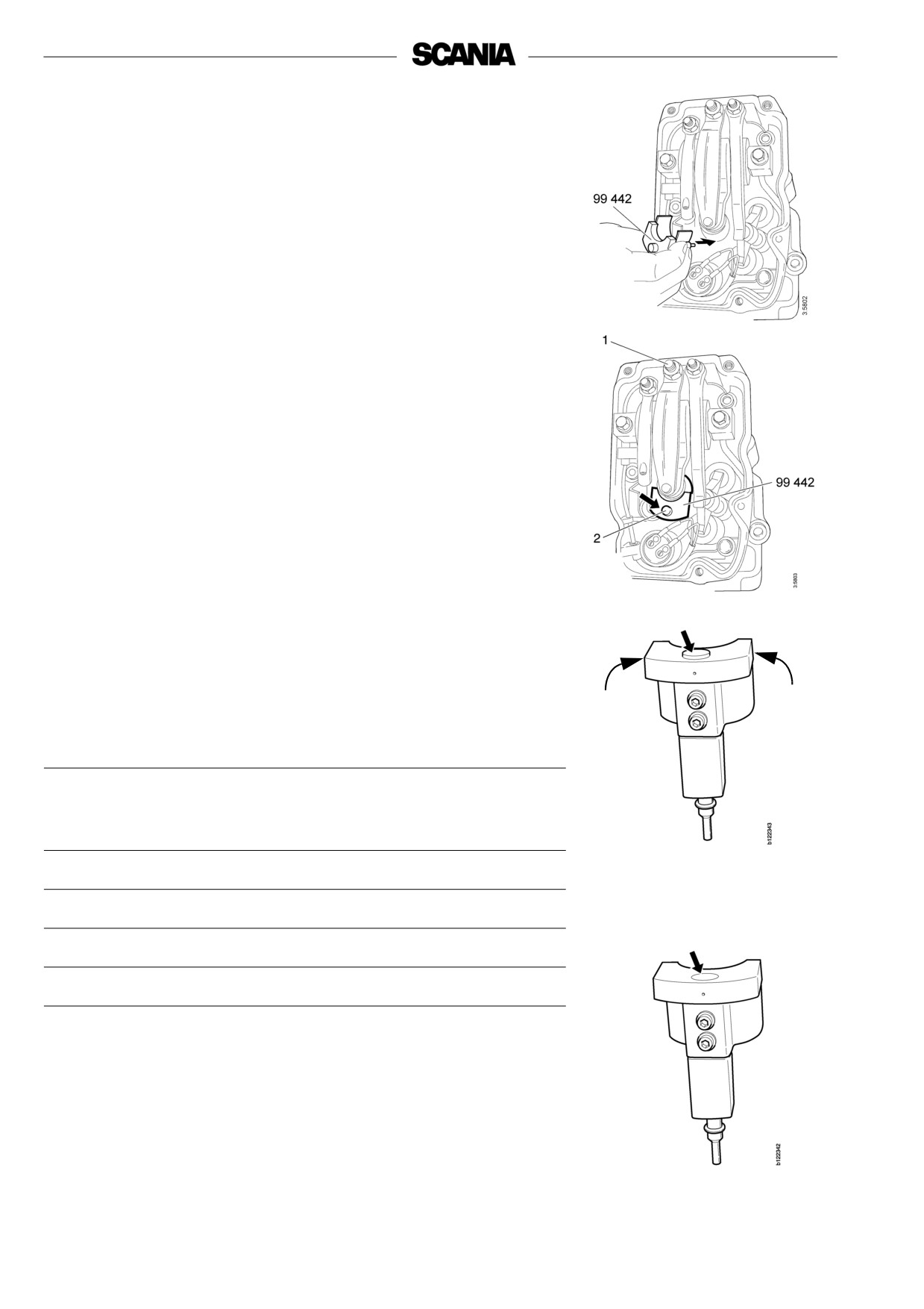
PDE32:
1. First, measure the distance (A) between plane (a) and the top edge of the
valve spring collar on the unit injector using a digital sliding calliper.
See figure.
2. Dimension (A) should be 69.9 mm for PDE32 (dimension B=38.8 mm).
3. The dimension is adjusted by undoing the lock nut and screwing the
rocker arm adjusting screw (1) to the correct measurement.
WARNING! Take care when carrying out the adjustment if the
dimension is well outside the adjustment dimension.
The spring is pre-tensioned and can cause personal
injury if it is released.
4. Position setting tool 99 442 with the metal plate around the injector
spring.
5. Finely adjust dimension (A) by simultaneously using a finger to sense
that the small piston (2) is level with the flat upper surface of the tool. It
is possible to feel differences of less than a tenth of a millimetre.
6. If the setting tool is not available, a digital sliding caliper can also be
used for fine adjustment. The rocker position is adjusted using the
adjusting screw to 69.9 ±0.1 mm as stated above.
7. Tighten the adjusting screw lock nut to 39 Nm and remove the tool.
8. The order in which the injector rocker arms are to be checked/adjusted is
shown in the table below.
Note: Additional checking and adjustment of the PDE injectors,
e.g. checking the opening pressure, must not be carried out.
Faulty injectors must always be replaced completely.
Order of adjustment:
69.9
99
442
- Turn the flywheel so that the marks on the flywheel can be seen in the
lower opening in the flywheel casing
Valve
Adjust injector
Mark on flywheel
transition on
rocker arm on
cylinder
cylinder
TDC Down (0°)
6
4 and 5
Piston above or below the flat
surface. Adjustment necessary
TDC Up (180°)
7
2 and 6
TDC Down (360°)
1
3 and 7
TDC Up (540°)
4
1 and 8
Piston level with the flat surface.
The adjustment is correct
50
Preparing the engine for
storage
If the engine is not to be used for a lengthy period of time, special measures
should be taken to protect the cooling system, fuel system and combustion
chamber from corrosion and the exterior from rusting.
The engine can normally stand idle for up to 6 months. If it remains unused
for longer than this the following measures, which provide protection for
about 4 years, should be adopted. An alternative to preparing the engine for
long-term storage is to start the engine and warm it up every 6 months.
Preparing the engine for storage means:
- Thoroughly cleaning the engine.
- Running the engine for a certain time using special preservative fuel, oil
and coolant.
- Otherwise preparing the engine for storage (filter renewal, lubrication,
!
etc.).
WARNING
Ethylene glycol can
Preservative coolant
be fatal if ingested.
If the engine is to be stored with a full cooling system, use coolant containing
Avoid contact with the skin.
50 percent glycol by volume. Glycol without nitrite-based inhibitor should be
used. E.g. BASF G48 or BASF D542
Preservative fuel
- Use diesel mixed with Lubrizol 560H or the equivalent.
- Mix 1 cm³ (ml) of Lubrizol 560H in 10 dm3 (l) of fuel.
!
HANDLING LUBRIZOL 560H
Hazardous!
Contains aromatic hydrocarbons
Use spot extractors where there is a danger of vapour build-up.
Wear protective gloves and goggles when handling Lubrizol. Do not use contaminated clothing.
If it gets in your eyes: Rinse with a gentle stream of water (at least 15 minutes). Seek medical attention.
If it gets on your skin: Wash the affected area with soap and water
If you inhale it:
Fresh air, rest and warmth
Flammable:
Fire class 2A. Flashpoint +27°C.
In the event of fire: Extinguish with carbon dioxide, powder or foam
Storage:
In a well-sealed receptacle in a dry, cool place. Keep out of reach of children.
51
Preservative oil
Suitable preservative oils are available from most oil companies, e.g. Dinitrol
40 or the equivalent.
Preparations for storage
Help protect our
- Drain and flush the cooling system. Top up with preservative coolant.
environment!
- Warm up the engine on normal fuel. Stop the engine and drain the oil.
Use a container to avoid spills
- Renew the fuel filter.
when
- Fill the engine with preservative oil up to the minimum level on the
draining the oil and coolant.
dipstick.
Dispose of used oil and coolant
- Mix preservative fuel in a can. Detach the fuel pipe at the feed pump
through an authorised waste
suction line and connect a hose from the can.
disposal contractor.
- Detach the fuel pipe at the overflow valve and connect a return hose to
the can.
- Start the engine and run it at about 1,000 rpm (not single-speed engines)
for 20-25 minutes.
- Stop the engine, remove the hoses and connect the normal fuel lines.
- Remove the rocker covers and lubricate the valve mechanisms and PDE
mechanisms with preservative oil. Refit the rocker covers.
Note: The unit injectors must not be removed.
- Drain the preservative oil from the engine. Fresh engine oil can be filled
directly or when preparing the engine for use.
- Drain the coolant if the engine is not to be stored with coolant in the
system. Plug and tape over all coolant connections (if the cooling system
is not completely assembled).
- Drain the sea water system.
- Air cleaner: clean or renew the filter element.
- Cover air intakes and exhaust pipes.
- Alternator and starter motor:
- Spray with water-repellent anti-corrosive oil, CRC 226, LPS1 or the
equivalent.
- Spray the outside of bright engine parts, first with penetrating
preservative oil such as Dinitrol 25B and then with Dinitrol 112 or the
equivalent.
Winter storage
- To reduce the risk of condensation in the fuel tank during winter storage,
fill the tank with fuel.
52
- Attach a label to the engine, clearly stating the storage preparation
date and that the engine must not be started or cranked.
ENGINE PREPARED FOR
LONG-TERM STORAGE
Date
Do not start or crank!
!
Batteries
WARNING
Remove the batteries for trickle charging at the battery charging station. This
does not apply to batteries specified as maintenance-free by the manufacturer.
Wear gloves and protective
The same applies to short-term storage, even if the engine has not been
prepared for storage as above.
goggles when charging and
handling batteries.
Storage
The batteries contain a highly
After the preparations, the engine should be stored in a dry and warm place
corrosive acid.
(room temperature).
Preparation for use
(Procedure for taking the engine into operation)
- Remove plugs and tape from coolant connections, air intakes and
exhaust pipes.
- Fill the system with coolant, see page 18.
- Connect the sea water system.
- Check the oil level in the engine or top up with fresh engine oil.
- Lubricate the valve mechanisms and their pushrods and valve tappets as
well as the PDE injector mechanisms.
- Drain the preservative fuel from the fuel manifolds and fuel filter.
- Connect and bleed the fuel system, see page 43.
- Wash off any externally applied preservative oil using white spirit.
53

Technical data
General
DI16
Number of cylinders
8 (V8, 90°)
Cylinder diameter
mm
127
Piston stroke
mm
154
Displacement
dm3 (litre)
15.60
No. of main bearings
5
Firing sequence
1 - 5 - 4 - 2 - 6 - 3 - 7 - 8
Compression ratio
16:1
Engine direction of rotation viewed from rear
Anti-clockwise
Fan direction of rotation viewed from front
Clockwise
Cooling
Liquid
Valve clearances, cold engine
intake valve
mm
0.45
exhaust valve
mm
0.70
Weight with heat exchanger, without coolant or oil kg
1,550
Power
See "Engine record card"
Lubrication system
Max. oil pressure
warm engine running at a
6
speed above 1,000 rpm
bar (kp/cm2)
Normal oil pressure
warm engine at operating speed
bar (kp/cm2)
3-6
Min. oil pressure
warm engine 1,000 rpm
bar (kp/cm2)
3.0
Min. oil pressure
warm engine, idling
bar (kp/cm2)
1.4
Oil capacity, see page 27
Crankcase pressure with closed crankcase ventilationmm
-55 - +20
water column
54

Fuel system
DI16
Low idling
rpm
700 (adjustable 500-800)
Maximum full load speed
See engine card
Fuel
Diesel1
1 see page 56
Cooling system
Number of thermostats
1 (dual thermostat)
Thermostat, opening temperature
°C
79
Coolant temperature:
system at atmospheric pressure
°C
70-93
system at overpressure
°C
70 - approx. 100
Volume including heat exchanger and expansion tank
95
Electrical system
System voltage
V
24
Alternator, current
A
140
Starter motor output
kW (hp)
6.7
(9.1)
Monitors, threshold values:
oil pressure monitor
bar (kp/cm2)
1.0 ± 0.15
temperature monitor
°C
Stamped on hexagonal part of monitor
55

Fuel
Diesel
The composition of the diesel is very important for the operation and service
life of the engine and injection system. The engine output and exhaust
emissions are also dependent on the fuel quality. The requirements and
testing standards for the most important properties are described in the
Workshop Manual in sections which can be ordered from Scania dealers or
directly from Scania. Scania's address is printed on the cover.
Diesel must comply with the following standard: EN 590 (European
standard).
The table below shows the requirements for some of the most important
properties.
Property
Requirements
Viscosity at 40°C
2.0-4.5 mm2/s (cSt)
Density at 15 °C
0.82-0.86 kg/dm³
Sulphur (concentration by mass)
max 0.3%
Ignitability (CET rating)
min. 49
Flashpoint
56°C
Biofuel (low sulphur fuels)
There are 3 different classes of biofuels (SS15 54 35).
Class 1 is sulphur-free and class 2 is low in sulphur. Compared with class 3
(normal fuel), these fuels are less dense and this reduces engine power. Only
class 1 fuel should be used with a catalytic converter.
Short term use of fuel with a higher sulphur content than 0.05% by weight
will not cause permanent damage to the catalytic converter.
The catalytic converter may, however, require fuel with a low sulphur content
for some time after this to regain its normal efficiency.
56
Temperature dependence of diesel
At temperatures lower than those specified for the diesel, paraffin wax may
!
precipitate from the fuel and block filters and pipes. The engine can then lose
Important
power or stop.
The diesel is adapted for use in the specific climate of each country. If a
It is not permitted to mix
vehicle or an engine is to be operated in a temperature zone with lower
kerosene with diesel that is
temperature than normal, first identify the temperature properties of the fuel
already adapted for the climate
concerned.
concerned. The injection
The properties of the fuel when cold can be improved by adopting one of the
equipment may be damaged. All
following measures before the temperature drops:
use of paraffin other than
- If the fuel concerned cannot cope with the expected temperatures, and
kerosene is forbidden, as it
diesel is not available with the correct temperature properties, Scania
causes engine damage.
recommends that an electric fuel heater is installed as a preventive
measure.
- The low temperature properties of diesel may be improved by adding
kerosene as a preventive measure. A maximum of 20% may be added.
When refuelling, the kerosene should be added first, so that it mixes
thoroughly with the diesel.
!
Note: It is prohibited to use kerosene in engine fuel in some countries.
Important
- To prevent water in the fuel from freezing and forming ice, a maximum
of 0.5-2% alcohol (isopropanol) may be added.
It is not permissible to mix
petrol with diesel. Petrol may
Drain fuel tanks and drain or renew fuel filters regularly.
cause wear to the unit injectors
and it may also cause damage to
the engine.
57

EC declaration of conformity
The following declaration of conformity applies to the DI16 45M with an
engine output of 662 kW. The declaration guarantees that the engine is
classified as suitable for recreational craft according to directive 94/25/EC.
58
Alphabetical index
Air cleaner
40
Oil level
27
Air cleaner, vacuum indicator
40
Oil pressure
22
Air filter, element
40
Preface
2
Batteries
44
Preparation for use
53
Battery, renewing
45
Preparations for storage
51
Bleeding, fuel system
43
Running
20
Certified engines
5
Checks after running
23
Safety information
6
Checks before running
19
Safety precautions for care and maintenance ..8
Coolant
33
Safety precautions for handling materials
8
Coolant level
31
Safety precautions for running the engine
7
Coolant level monitor
45
Starting the engine
19
Coolant temperature
21
Stopping the engine
23
Coolant, changing
35
Storage
53
Cooling system
31
Cooling system, cleaning
36
Technical data
54
Corrosion inhibitor
35
Troubleshooting, control unit
14
Troubleshooting, coordinator
16
Drive belt
46
Type designations
10
Electrical system
44
Unit injector
48
EMS sensors
13
Engine speed
20
Vacuum indicator
40
Environmental responsibility
4
Valve clearance
48
Filter, air cleaner
40
Warranty
1
Filter, fuel
42
First start
18
Flash codes, control unit
15
Flash codes, coordinator
17
Fuel filter, renewing
42
Fuel level
42
Fuel specifications
56
Fuel system
42
Fuel system, bleeding
43
Glycol
33
Inspection schedule
25
Leakage
47
Lubricating oil pressure
22
Lubrication system
26
Maintenance
24
Oil analysis
26
Oil capacity
27
Oil change
27
Oil filter
28
Oil filter
30
Oil grade
26
59
Scania Assistance
Wherever you are, you can always get assistance from the Scania service organisation, Scania Assistance, all day,
every day of the year. Using Scania Assistance is free, but the cost of repairs, spare parts and help from mechanics
will be debited.
Always call the contact for your country.
AR
0800 999 722 642
IE
+353 71 9634000
AT
+43 1 256 44 11
IT
+39 0461 996 222
AU
1300 SCANIA
KR
+82 1588 6575
1300 722642
LU
+32 226 400 000
BE
+32 2 264 00 00
MA
+34 91 678 92 13
BG
+359 886 660001
MX
01 800 4SCANIA
BR
0800 019 42 24
NL
+31 70 4182666
CH
+41 800 55 24 00
NO
+47 223 217 00
CL
188 800 722 642
PL
+48 602 622 465
CZ
+420 225 020 225
PT
+48 91 678 9247
DE
+49 261 887 8888
RO
+40 723 27 27 26
DK
+45 333 270 44
SE
+46 42 100 100
ES
+34 91 678 80 58
SK
+421 903 722 048
FI
+358 10 555 24
TR
+90 212 335 04 40
FR
+33 2 414 132 32
TZ
+255 78 472 2642
GB
0 800 800 660
UY
0800 8351
+44 1274 301260
ZA
0800 005 798
GR
+30 6944 420 410
+27 11 661 9823
HU
+36 209 727 197
Other countries: +46 8 52 24 24
24
Note: Calls will be recorded for training purposes.
60