Scania OC16 Gas. Industrial engine en-GB 2 831 273. Operator’s manual - part 4
Fuel system
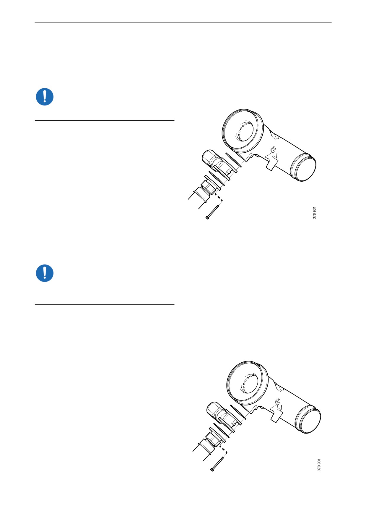
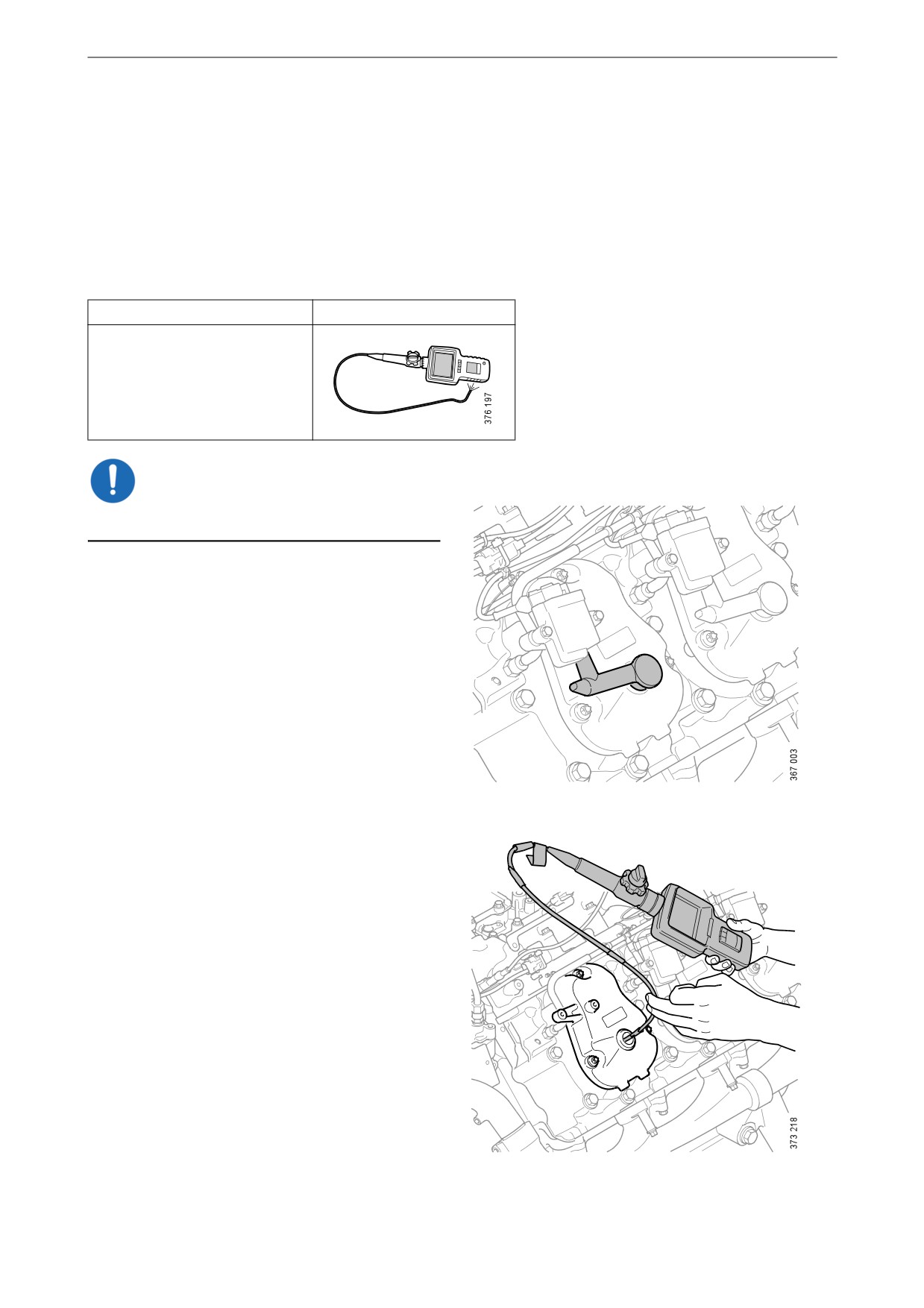
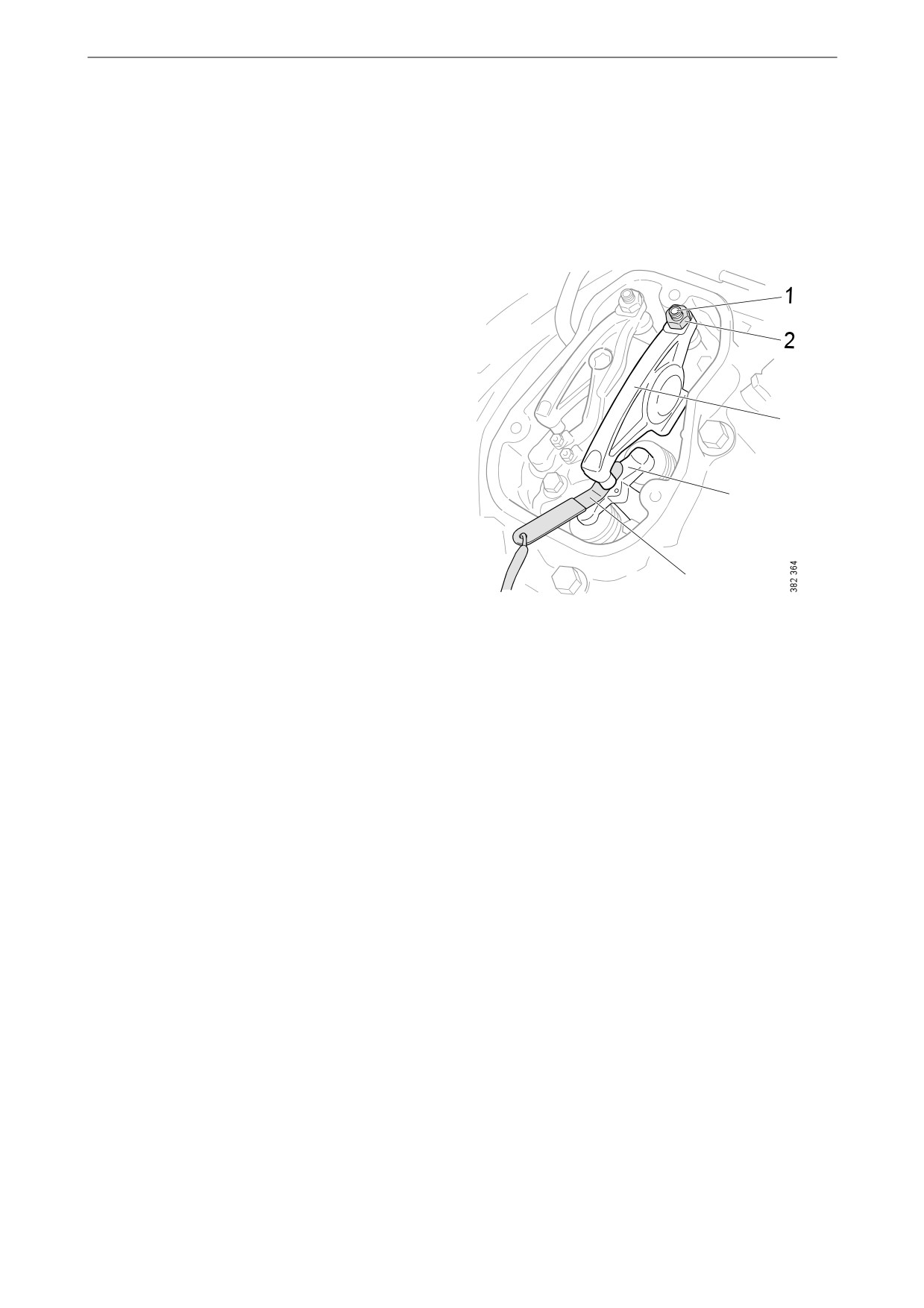
Cleaning the throttle at the
gas mixer
This procedure applies only if pure biogas is
used as fuel.
IMPORTANT!
Read the safety precautions before starting work.
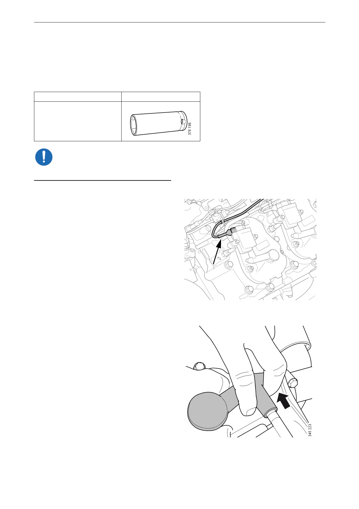
1. Detach the harness-to-component connector
from the throttle.
2. Remove the screws and detach the fuel hose
and the throttle.
3. Protect the throttle electrical connection
from moisture.
4. Clean the throttle with soap and water. Use a
soft brush to remove stubborn dirt.
IMPORTANT!
Only use soap and water. Solvents and degreas-
ing agents can damage the throttle.
5. Rinse the throttle with hot water.
6. Dry off the water.
7. Spray the outside of the throttle with water-
repellent anti-corrosive oil, for example
LPS1 or equivalent. Make sure that the oil
reaches the holes for the throttle shaft in the
throttle housing.
8. Fit the gas mixer housing.
9. Renew the gaskets.
10. Fit the throttle and gas connection.
11. Check the fuel system is not leaking. See the
following section.
48

Fuel system
Leak testing after mainte-
nance of the fuel circuit
This procedure applies only if pure biogas is
used as fuel.
Special tool
Number
Designation
2 541 520
Pressure testing kit
Calibration of the pressure testing
equipment
1. Connect pressure regulator 2 301 551 to the
compressed air.
2. Block the connection nipple and open the
pressure regulator valve.
49

Fuel system
3. Adjust the pressure regulator so that the ma-
nometer shows 7 psi.
50
40
60
30
70
20
80
10
90
0
100
4. Lock the pressure regulator adjustment rota-
ry control and close the valve.
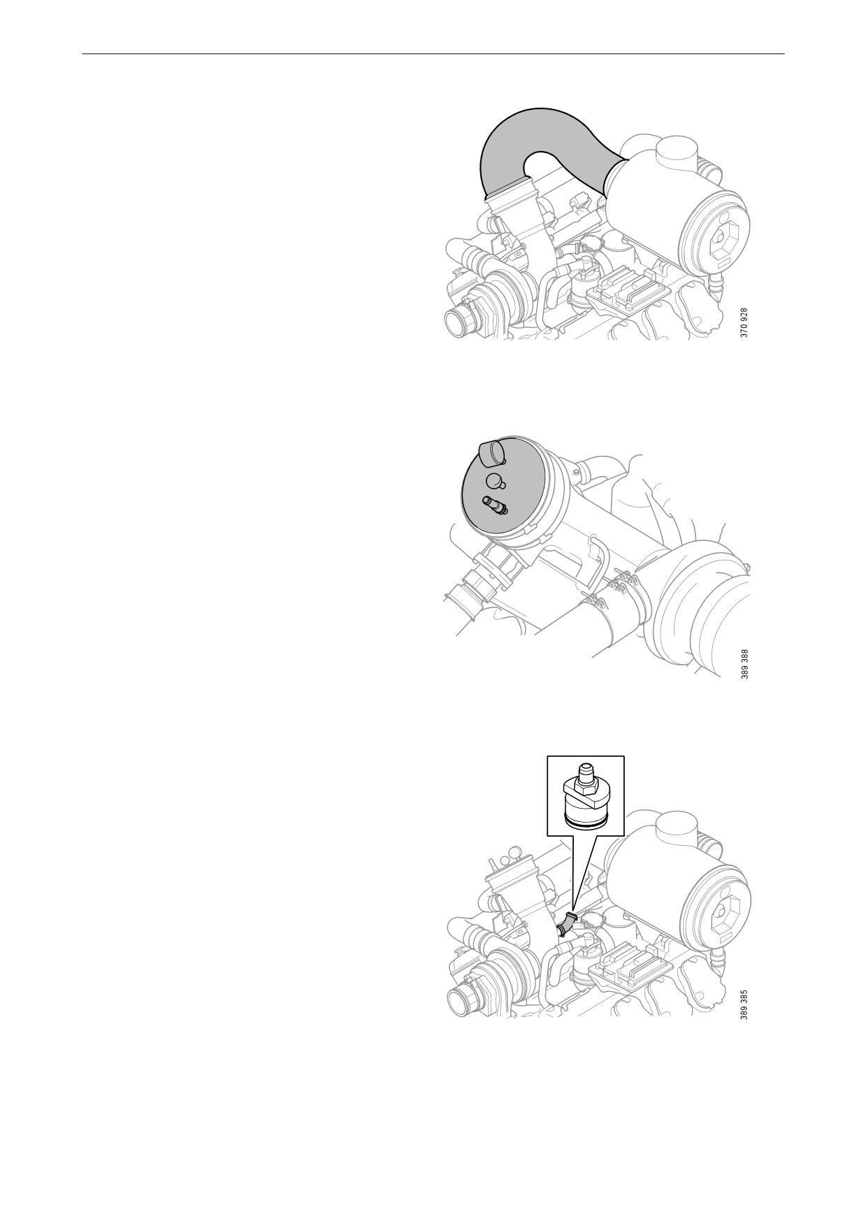
Leak testing the intake system up-
stream of the throttle
1. Undo the hose clamps.
2. Turn the charge air pipe downwards.
3. Close the nipple on pressure cap 2 655 714
and fit the cover to the hose spigot.
4. Tighten the hose clamps.
50
Fuel system
5. Remove the air pipe between the air cleaner
and the gas mixer.
6. Fit pressure cap 2 541 521 in the hose spigot
on the gas mixer.
7. Detach the crankcase ventilation connection.
8. Fit cover 2 655 695.
9. Connect pressure regulator 2 301 851 to cov-
er 2 655 695.
51

Fuel system
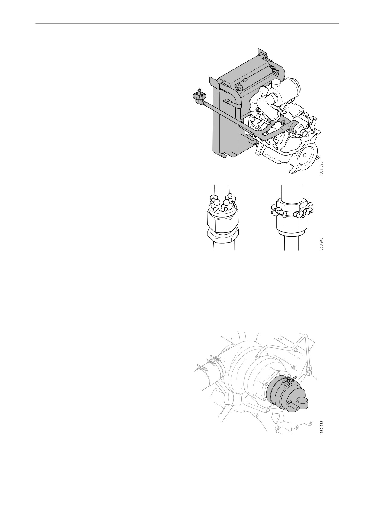
10. Open the valve on pressure regulator
2 301 851.
11. Monitor the pressure on pressure cap
2 541 521. The manometer should indicate a
pressure below 0.3 bar. Greater pressure may
damage the engine.
52
Fuel system
12. Use leak detection spray to locate any gas
leakage. If there is a gas leak, bubbles form
upon application of leak detection spray.
Be careful in areas where work has been car-
ried out or where a joint has been cut.
13. If you discover a leak, rectify the leakage and
repeat the leak tracing.
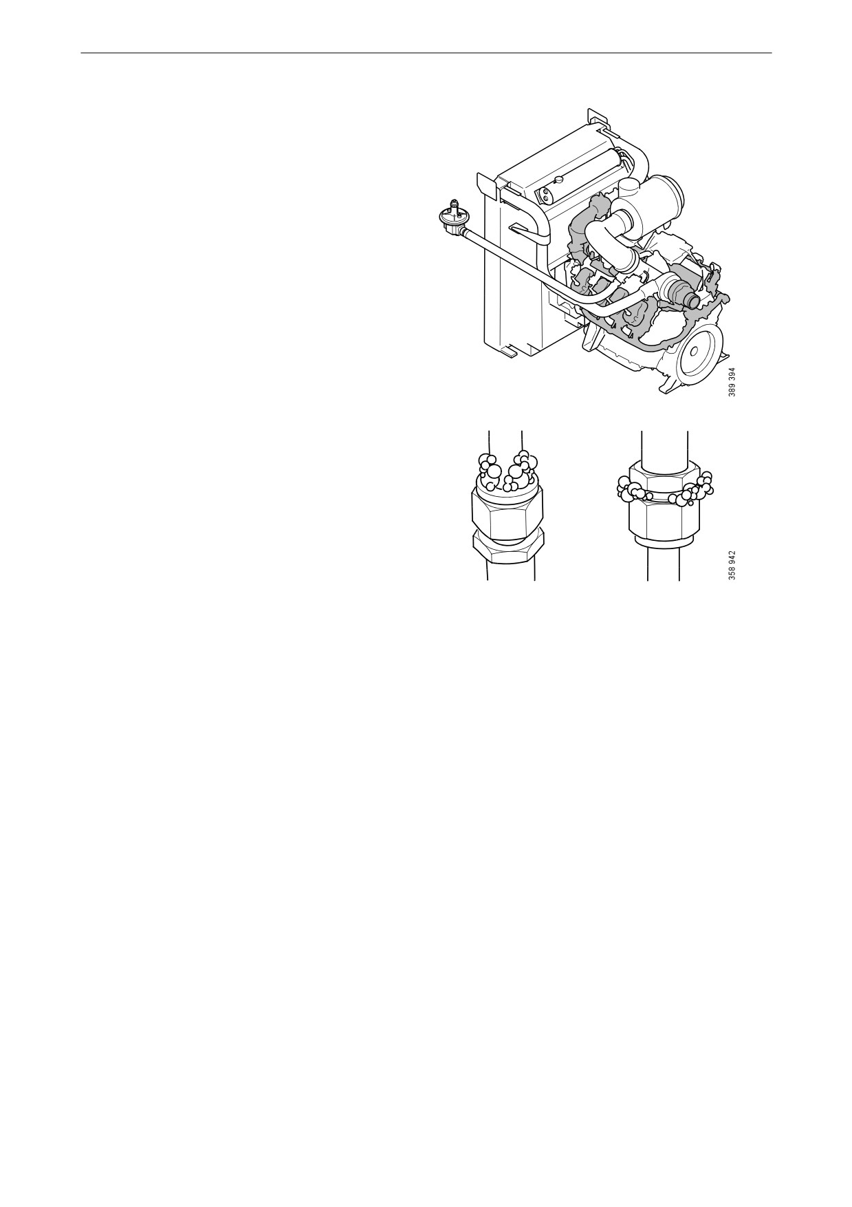
Leak testing the intake system down-
stream of the throttle
1. Remove the V-clamp and move the exhaust
pipe to one side.
2. Remove the O-ring from the pressure testing
equipment 2 284 630. Fit adapter 2 541 522
and the pressure testing equipment and plug
the pneumatic connection with cover
2 655 696.
Fit the pressure testing equipment with
adapter.
53

Fuel system
3. Remove the hose spigot and pressure cap
2 655 714 from the charge air pipe.
4. Open the nipple on pressure cap 2 655 714.
5. Fit adapter connection 2 655 697 to the pres-
sure regulator and connect it to pressure cap
2 655 714.
6. Fit the hose spigot and pressure cap
2 655 714 at the throttle housing.
7. Open the valve on pressure regulator
2 301 851.
8. Monitor the pressure on pressure testing
equipment 2 284 630. The manometer
should indicate a pressure below 0.3 bar.
Greater pressure may damage the engine.
IMPORTANT!
The pressure must not exceed 0.3 bar. A higher
pressure may damage the turbocharger.
54
Fuel system
9. Use leak detection spray to locate any gas
leakage. If there is a gas leak, bubbles form
upon application of leak detection spray.
Be careful with areas where work has been
carried out or where a joint has been cut.
The exhaust system up to the turbocharger
outlet is pressurised, but does not need to be
checked.
10. If you discover a leak, rectify the leakage and
repeat the leak tracing.
55
Fuel system
Checking deposits in the
combustion chamber
The procedure only applies if pure biogas is used
as fuel, and after cleaning the flame arrestor and
throttles in accordance with the previous two
sections.
Tools
Designation
Illustration
Endoscope
IMPORTANT!
Read the safety precautions before starting work.
1. Remove the spark plug connection and the
spark plug. See the section Renewing the
spark plugs.
2. Check if there are any deposits in the com-
bustion chamber using an endoscope.
3. Check the amount of deposits on the top of
the piston.
The cylinder, piston and the valve head must
be cleaned if
- deposits on the top of the piston are flak-
ing,
or if
- the deposit protrudes at least 5 mm from
the valves.
The cleaning procedure is described in the
Workshop Manual, which can be ordered
from a Scania dealer or directly from Scania.
4. Repeat steps 1-3 on the other cylinders.
56
Electrical system
Electrical system
Renewing the spark plugs
Tools
Designation
Illustration
Spark plug socket
IMPORTANT!
Read the safety precautions before starting work.
1. Disconnect the ignition coil harness-to-com-
ponent connector.
2. Twist off the spark plug connector arm later-
ally.
57

Electrical system
3. Remove the spark plug connector by pulling
it straight upwards.
IMPORTANT!
Do not pull on the arm as this could damage the
spark plug connector.
4. Check that the spark plug connector does not
have any visible damage.
5. Unscrew the spark plug using the spark plug
socket.
IMPORTANT!
Do not touch the spark plug insulator with your
fingers. If this occurs, clean the insulator with al-
cohol.
6. Place the new spark plug in the spark plug
socket and tighten the spark plug. Tightening
torque 30 Nm (22 lb-ft).
IMPORTANT!
Do not lower the spark plug through the rocker
cover since this could cause the gap between the
spark plug electrodes to be incorrect. Always
place the spark plug in the spark plug socket be-
fore fitting. The correct gap between the spark
plug electrodes is 0.25 mm.
7. Fit the spark plug connector.
58

Other
Other
3
2
Checking the drive belt
5
IMPORTANT!
2
Before starting, make a note of how the drive belt
is fitted. Refit the drive belt with the same direc-
tion of rotation as it had before removal.
4
1. Check the drive belt thoroughly, particularly
at the idler rollers.
2. Check the drive belt for cracks. Renew the
1
drive belt if deep cracks have formed.
Example of a drive belt.
Note:
1. Crankshaft
Small and shallow cracks are normal and form
2. Idler roller
after only a few hours of operation. They do not
3. Alternator
mean that the drive belt needs to be renewed. If
4. Belt tensioner
there are many deep cracks, or if parts of the
5. Coolant pump
drive belt have started to come off, the drive belt
must then be renewed.
Example of a minor crack in the drive belt. The drive
The drive belt has deep cracks and must be renewed.
belt can be refitted.
59

Other
3. Check drive belt wear. Renew the drive belt
if it is too worn.
The drive belt is starting to become worn, but can be
The belt is worn down to the cord. The drive belt
refitted.
must be renewed.
Checking for leaks
WARNING!
If there is leakage in the fuel system, contact
your nearest Scania workshop immediately.
IMPORTANT!
If there is a major oil or coolant leak, contact
your nearest Scania workshop.
1. Start the engine.
2. Check for oil, coolant, fuel, air or exhaust
leaks.
3. Tighten or renew leaking connections.
Check the overflow holes which show
whether the O-rings between the cylinder
liners and crankcase are leaking.
4. Check whether the drain hole on the coolant
pump is blocked. If there is a leak, renew the
seal in the pump or the complete coolant
pump.
60
Other
Checking and adjusting the
valve clearance
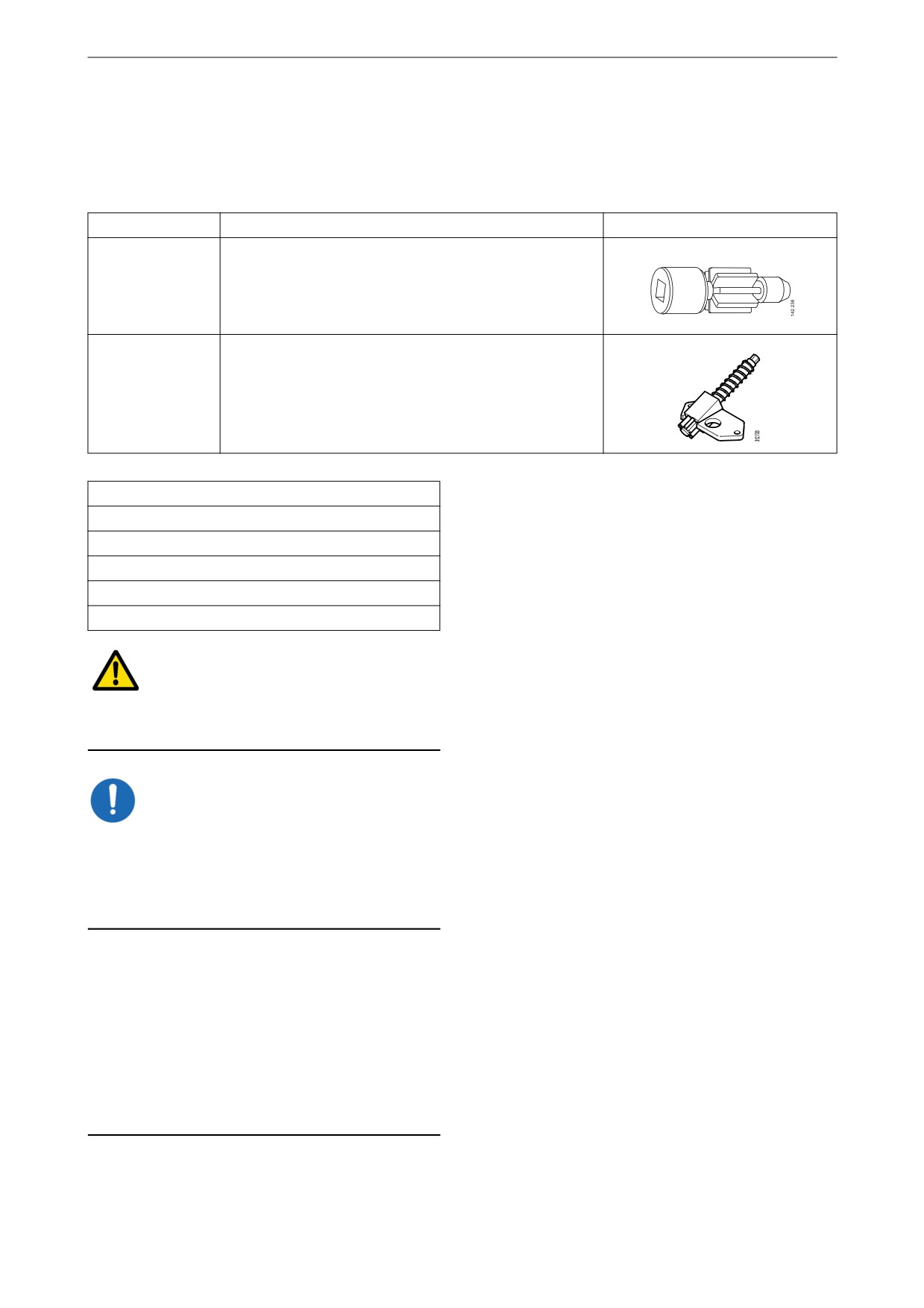
Special tool
Number
Designation
Illustration
99 309
Turning tool for rotating the flywheel from below.
2 402 509
Turning tool for rotating the flywheel from above
Other tools
Torque wrench, 0-50 Nm
Waterproof felt-tip pen
0.45 and 0.80 mm feeler gauges
Flash light
Mirror
WARNING!
Block the starting device. If the engine starts un-
expectedly, there is a serious risk of injury.
IMPORTANT!
The engine must be cold when the work is car-
ried out.
Remember to remove the turning tool from the
flywheel after adjustment.
Note:
Carry out the working without pausing, so that
no step is overlooked.
Carry out a check and adjustment of the valve
clearances one more time after the first 500 hours
of operation. After this, adjustment according to
the regular interval takes place, which is every
2,000 operational hours.
61
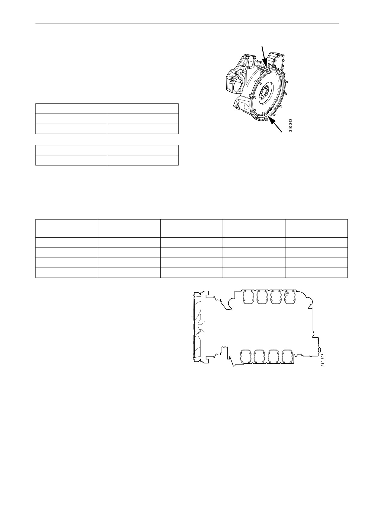
Other
The reference information UP TDC, DOWN
TDC and the angle indications listed in the table
below are engraved on the flywheel. Depending
on the engine installation, this information is vis-
ible in one of the windows, either furthest up or
furthest down on the flywheel. See illustration.
Valve clearance, specifications
Intake valve
0.45 mm (0.018 in)
Exhaust valve
0.80 mm (0.032 in)
Upper and lower window to read the engraving on
Tightening torque
the flywheel.
Lock nut for valves
35 Nm (26 lb/ft)
Adjust valves according to the table below. Fol-
low the respective column depending on whether
you are reading the engraving on the flywheel in
the lower or the upper window. Start adjustment
at the top of the table.
Reading in the low-
Valve transition on
Adjust intake valve
Adjust exhaust
Reading in the up-
er window
cylinder
on cylinder
valve on cylinder
per window
DOWN TDC (0°)
6
7 and 8
4 and 5
UP TDC (180°)
UP TDC (180°)
7
1 and 5
2 and 6
DOWN TDC (0°)
DOWN TDC (360°)
1
2 and 4
3 and 7
UP TDC (540°)
UP TDC (540°)
4
3 and 6
1 and 8
DOWN TDC (360°)
1
2
3
4
5
6
7
8
Order of cylinders.
62
Other
1. Clean the rocker covers and the area around
them.
2. Remove the rocker covers.
3. Use the turning tool appropriate to the instal-
lation of the engine. Tool 99 309 is used to
rotate the flywheel from the underside of the
engine and tool 2 402 509 is used from the
top side.
4. Start adjusting one cylinder according to the
table. Rotate the flywheel until the correct
engraving can be read on the flywheel. It
may be necessary to rotate it more than 1 rev-
olution.
Rotate the flywheel in the rotational direc-
tion of the engine, which is clockwise
viewed from the front of the engine and anti-
3
clockwise viewed from the back of the en-
gine.
During a valve transition, the exhaust valve
(the long arm) is closing at the same time as
4
the intake valve is opening.
The UP TDC engraving on the flywheel is
now visible in the window furthest up on the
flywheel. The DOWN TDC engraving is vis-
5
ible in the lower window.
1.
Adjusting screw
5. Read the table on the previous page to see
2.
Lock nut
which valve to adjust.
3.
Rocker arm
6. Stick the feeler gauge under the pressure pad
4.
Valve bridge
of the rocker arm and check the valve clear-
5.
Feeler gauge
ance.
7. If necessary, adjust the valve clearance by
a) loosening the lock nut on the end of the
rocker arm
b) adjusting the valve clearance with the ad-
justing screw
c) tightening the lock nut.
8. Mark the rocker arm with the felt-tip pen and
then continue with the next cylinder accord-
ing to the table.
63