Scania DC16 XPI. Industrial engine. Operator’s manual - part 5
Fuel system
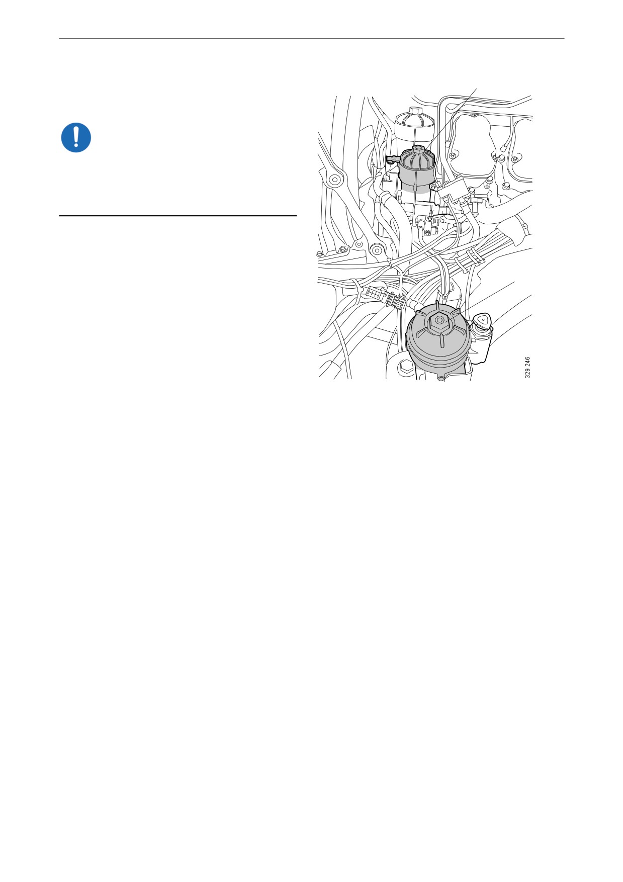
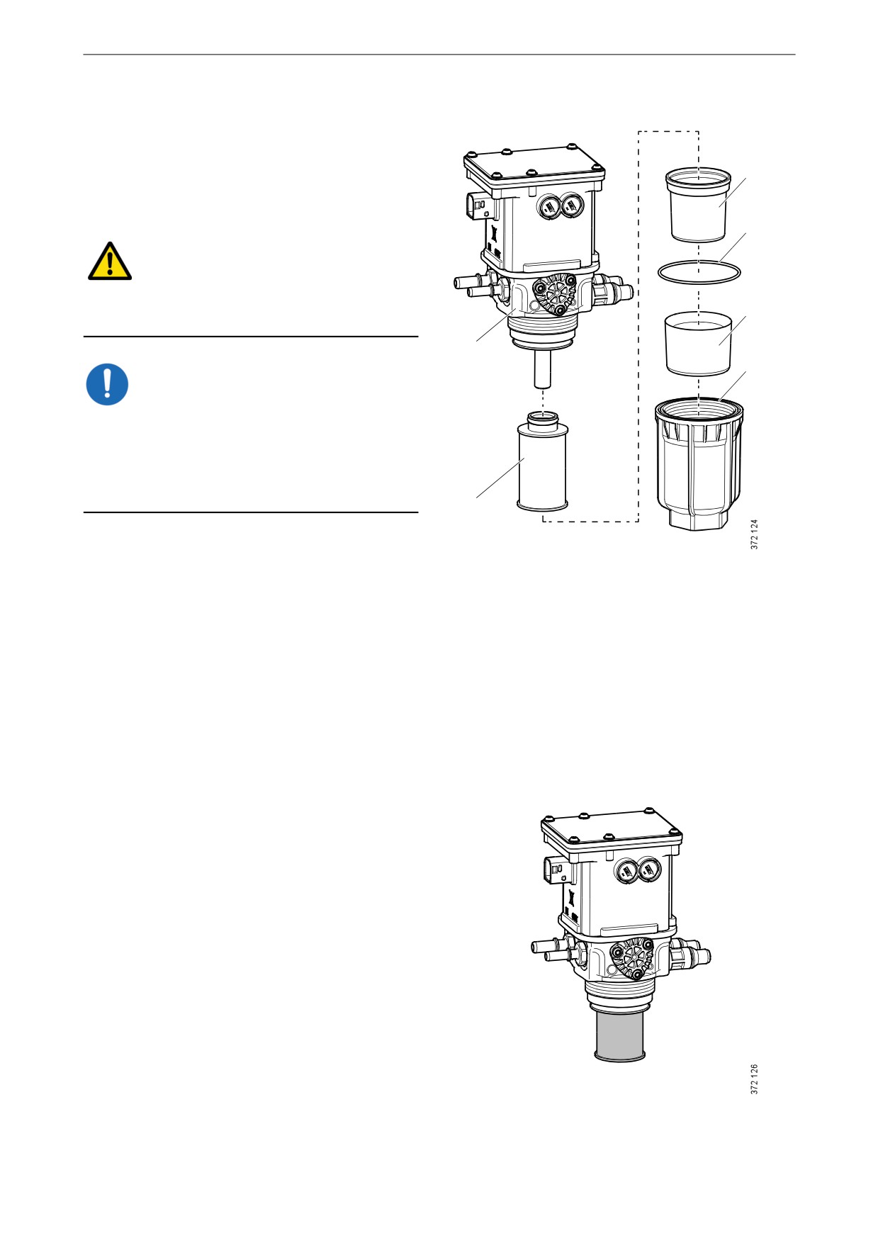
To ensure that the filter housings are drained
B
properly, the filter covers must be removed as
follows:
IMPORTANT!
Start with the water separating prefilter (A). Do
not open the main filter cover (B) until the filter
housing for the water separating prefilter is com-
pletely drained.
A
64
Fuel system
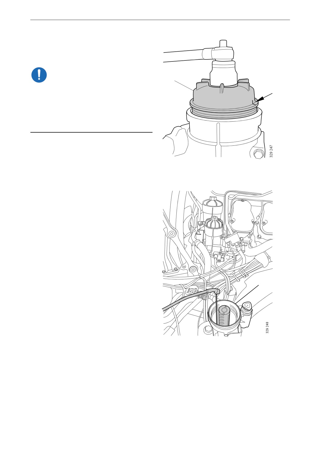
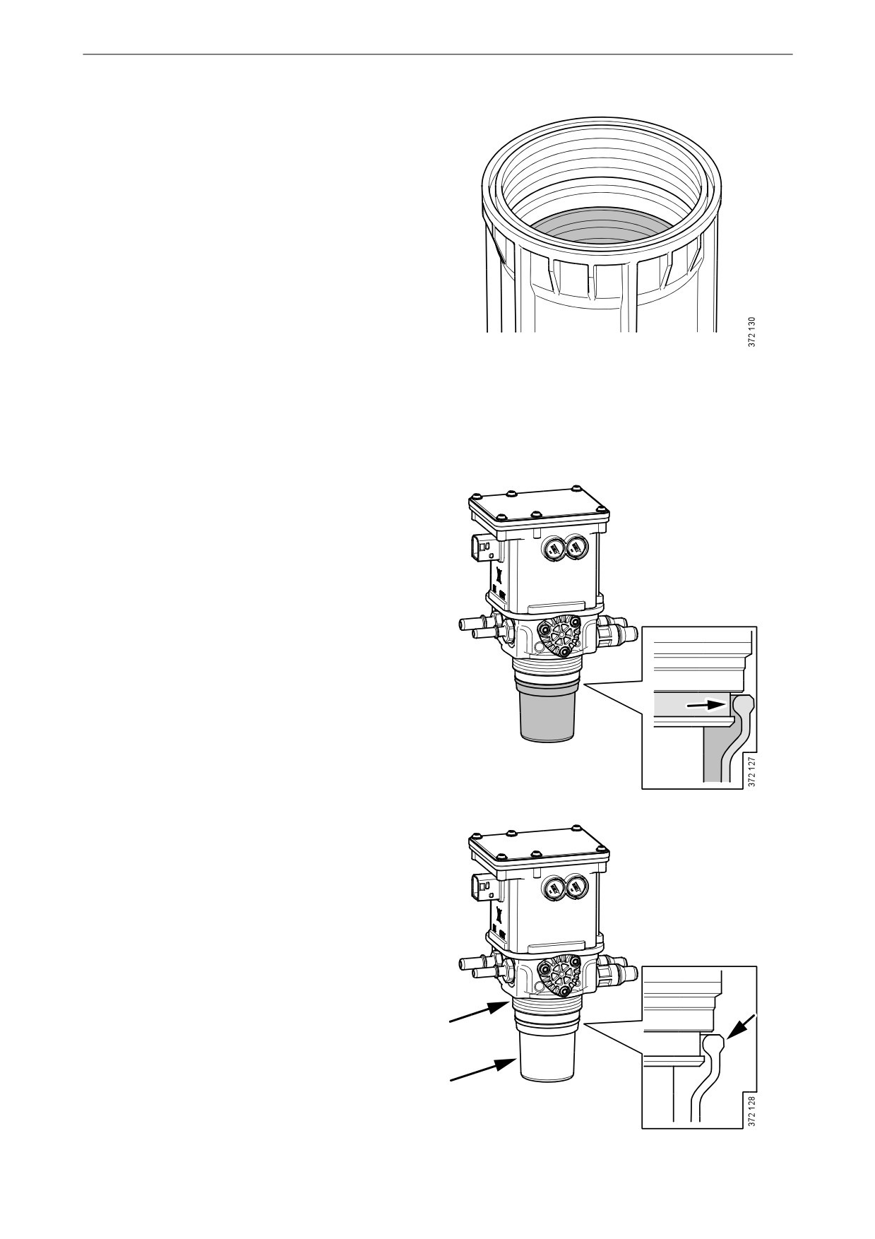
1. Make a mark on the water separating prefil-
ter cover (A). Unscrew the cover 3 to 4 turns
with the socket.
IMPORTANT!
A
Do not use an adjustable spanner or other open
tool to remove the filter covers, as the filter cov-
ers may then get damaged.
Wait for at least 2 minutes to allow as much of
the fuel as possible to drain out of the filter hous-
ing.
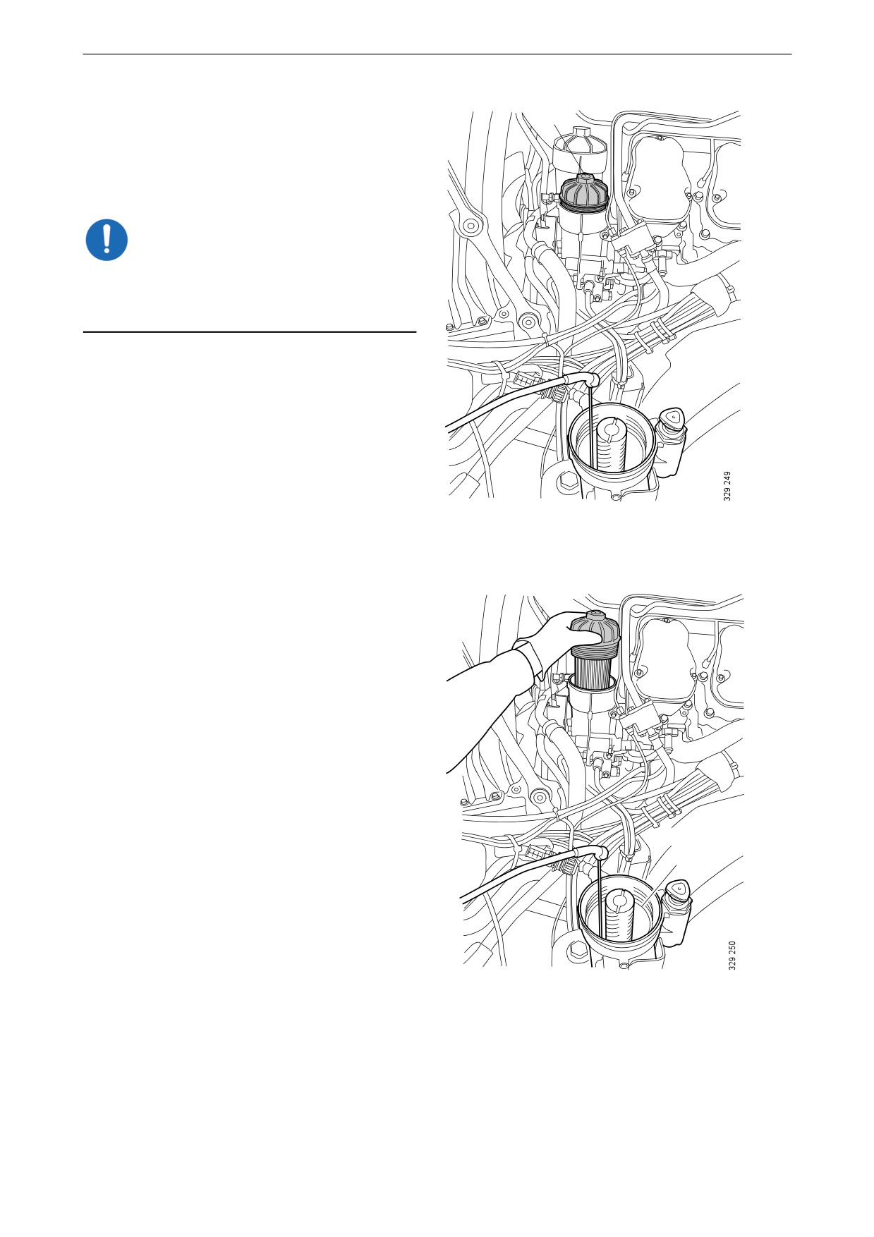
2. Unscrew the filter cover (A) and lift it up
slowly with the filter element.
3. Make sure the suction tool is completely
drained before starting work. Draw out re-
maining fuel and any particles using the suc-
tion tool or a similar tool.
4. Keep the suction tool hose in the filter hous-
ing for the water separating prefilter (A).
A
65
Fuel system
5. Make a mark on the main filter cover (B).
B
Unscrew the cover 3 to 4 turns with the sock-
et. Draw out fuel which may drain into the
water separating prefilter housing when the
main filter is detached.
IMPORTANT!
Wait for at least 2 minutes to allow as much of
the fuel as possible to drain out of the filter hous-
ing.
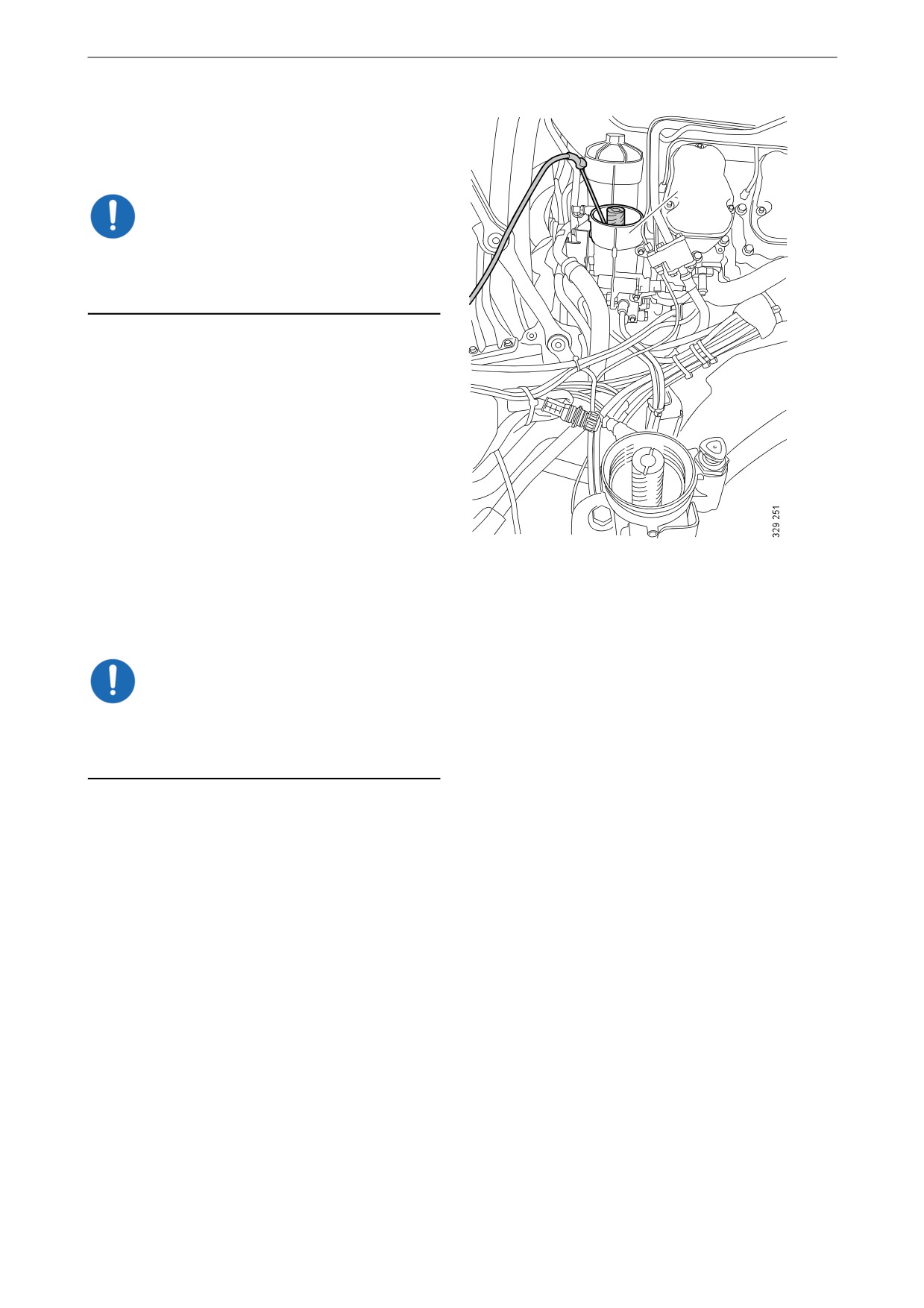
6. Unscrew the main filter cover (B) and lift it
up slowly with the filter element.
B
7. Fuel from the main filter housing (B) will
flow into the water separating prefilter hous-
ing (A). Leave the suction tool in the water
separating prefilter housing until it is com-
pletely drained of fuel.
A
66
Fuel system
8. Move the suction tool to the main filter hous-
ing (B). Draw out remaining fuel and parti-
cles.
B
IMPORTANT!
It is important to remove remaining fuel and par-
ticles from the filter housings to prevent fuel sys-
tem contamination.
9. Undo the old filter elements from the covers
by carefully bending them to one side.
Removing the fuel filter if there is no
suction tool
1. Open the bleed nipple on the fuel filter hous-
ing to release any remaining pressure. It may
be difficult to unscrew the filter cover if the
fuel pressure has not fallen sufficiently.
IMPORTANT!
Do not use an adjustable spanner or other open
tool to remove the filter covers, as the filter cov-
ers may then get damaged.
67

Fuel system
To ensure that the filter housings are drained
properly, the filter covers must be removed as
follows:
B
2. On the main filter (B): Make a mark on the
cover. Unscrew the cover 3 to 4 turns with
the socket.
3. Repeat the procedure with the water separat-
ing prefilter (A).
4. Wait at least 2 minutes to ensure the filter
housings have drained properly.
5. On the main filter: Unscrew the filter cover
and lift it up slowly with the filter element.
6. On the water separating prefilter: Unscrew
the filter cover and lift it up slowly with the
filter element.
Remaining fuel will drain out of the fuel fil-
A
ter housings automatically when the filter el-
ements are lifted out.
7. Check that no fuel or particles remain in the
bottom of the filter housings. Draw off re-
maining fuel and any particles.
IMPORTANT!
It is important to remove remaining fuel and par-
ticles from the filter housings to prevent fuel sys-
tem contamination.
8. Undo the old filter element from the cover by
carefully bending it to one side.
68
Fuel system
Fitting the fuel filters
IMPORTANT!
Check that there is no remaining packaging ma-
terial stuck to the new filter elements. Secure the
filter elements in the filter covers before posi-
tioning them in the fuel filter housings. Other-
wise, the filter elements may break.
In order to prevent back pressure in the filter
housings when the filter elements are screwed
on, the bleed nipple should be open.
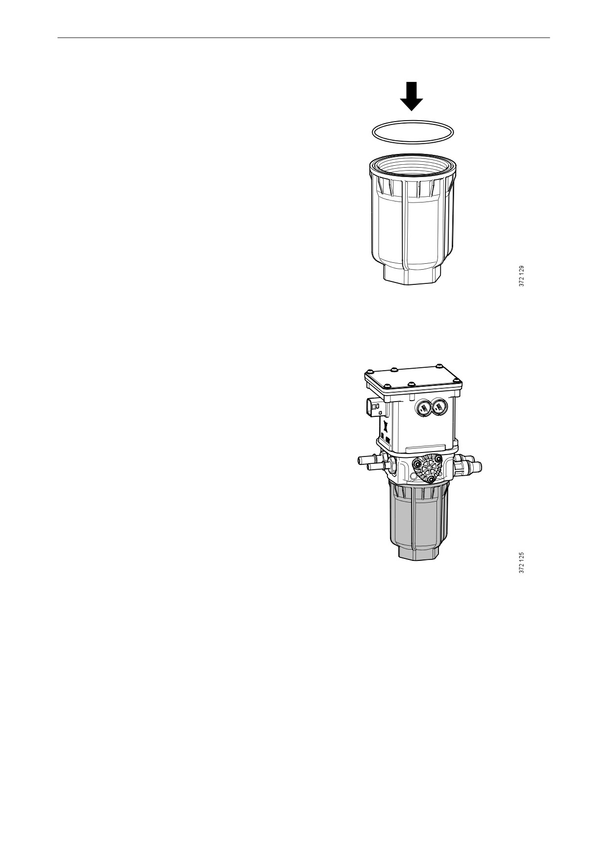
1. Fit a new O-ring on the cover. Lubricate the
O-ring with O-ring grease.
2. Press the filter elements into the snap fasten-
ers on the covers.
3. Check that the filter housing is clean before
fitting. Use lint free cloths.
4. Press down the filter elements into the fuel
filter housings with the filter covers.
5. Screw down the filter covers until the cover
seals are in contact with the filter housings.
Use the socket.
6. Tighten the filter housings to 25 Nm (18 lb/
ft).
7. Bleed the fuel system as per the following
section.
8. Start the engine and check that there is no
fuel leakage between the filter covers and fil-
ter housings. If there is leakage, undo the fil-
ter covers and start again from step 4.
69

Fuel system
Bleeding the fuel system
IMPORTANT!
The collected fuel must not be poured back into
the fuel tank.
Environment
Use a suitable container. The fuel collected must
be disposed of as specified in national and inter-
national laws and regulations.
Bleeding the fuel system using a suc-
tion tool
Tool
Description
Illustration
Suction tool
Note:
Scania recommends bleeding the fuel system us-
ing suction tools rather than with a hand pump.
This is a quicker and simpler method, which en-
sures a complete bleeding.
1. Open the bleed nipple on the high pressure
pump and connect the suction tool.
70
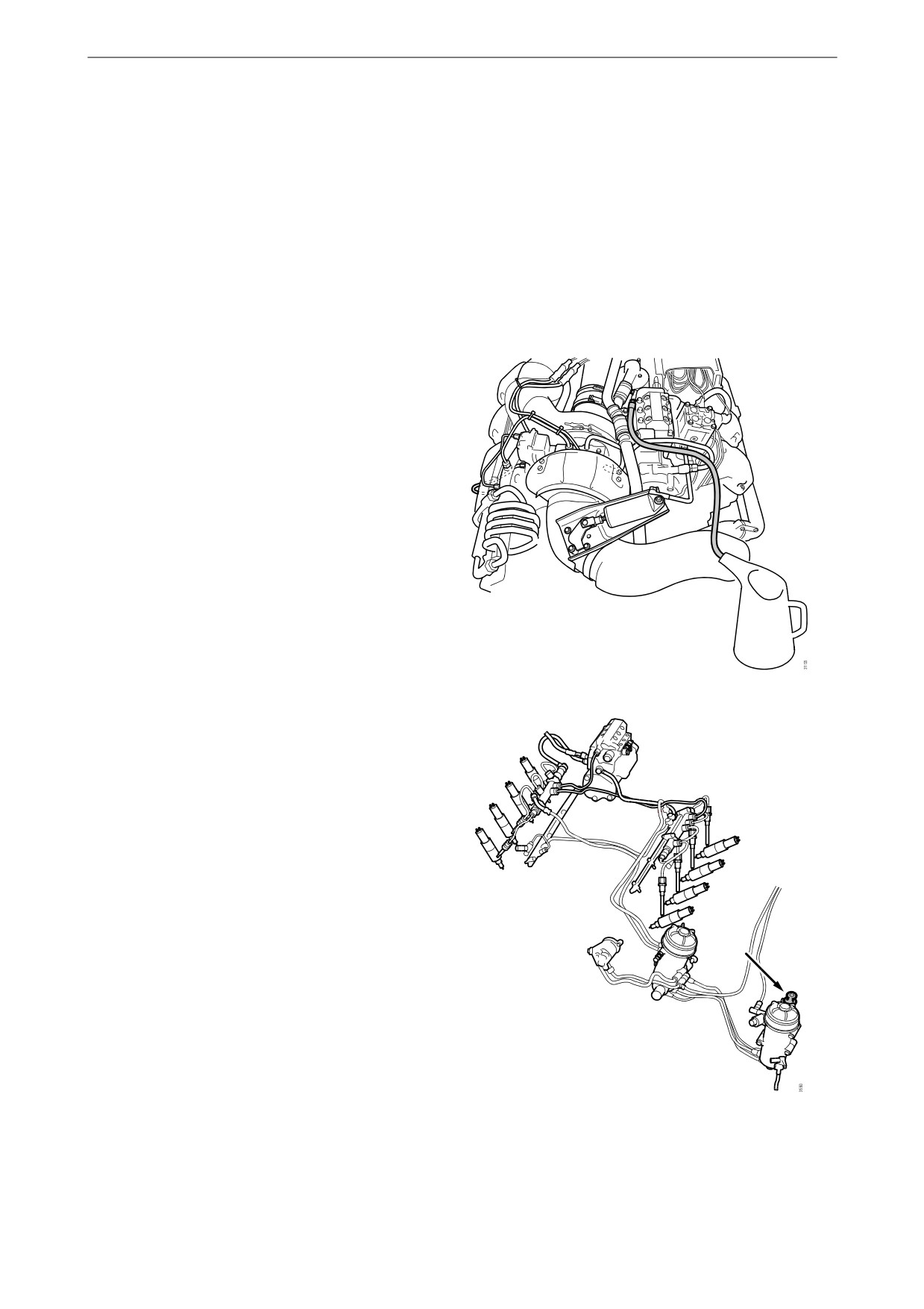
Fuel system
2. Hold the suction tool straight and draw out at
least a full container of fuel.
3. Once the fuel coming out of the hose is free
of air bubbles, then bleeding is complete.
4. Close the bleed nipple on the high pressure
pump. Remove the hose and suction tool.
5. Start the engine and check that no leakage
occurs.
Bleeding the fuel system using a
hand pump
1. Attach a clear plastic hose to the bleed nipple
on the fuel filter housing. Let the plastic hose
drop into a container that holds at least 5 li-
tres (1.3 US gallons).
2. Unscrew the hand pump handle on the water
separating prefilter.
3. Open the bleed nipple on the fuel filter hous-
ing and pump until fuel runs out, which will
take around 150 pump strokes. Close the
bleed nipple on the fuel pump and screw
down the hand pump handle.
The main filter has built-in bleeding in the
form of a 0.2 mm restriction valve in which
the fuel continuously flows on to the return
pipe and takes with it any air in the circuit.
4. Start the engine and check that no leakage
occurs.
71
Miscellaneous
Miscellaneous
3
2
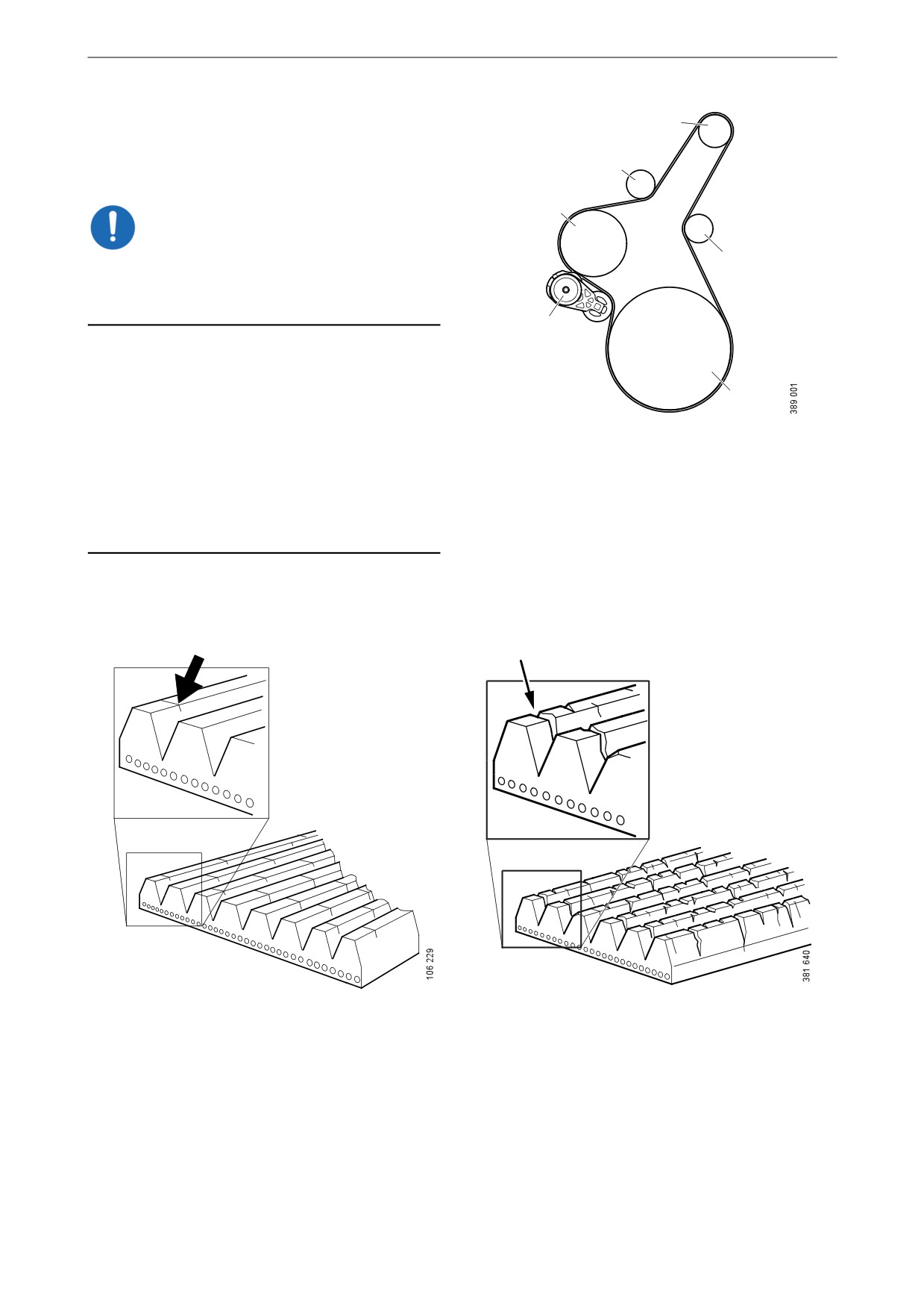
Checking the drive belt
5
IMPORTANT!
2
Before starting, make a note of how the drive belt
is fitted. Refit the drive belt with the same direc-
tion of rotation as it had before removal.
4
1. Check the drive belt for cracks. Renew the
drive belt if deep cracks have formed.
1
Note:
Small and shallow cracks are normal and form
Example of a drive belt.
after only a few hours of operation. They do not
1. Crankshaft.
mean that the drive belt needs to be renewed. If
there are many deep cracks, or if parts of the
2. Idler roller.
drive belt have started to come off, the drive belt
3. Alternator.
must then be renewed.
4. Belt tensioner.
5. Coolant pump.
Example of a minor crack in the drive belt. The drive
The drive belt has deep cracks and must be renewed.
belt can be refitted.
72
Miscellaneous
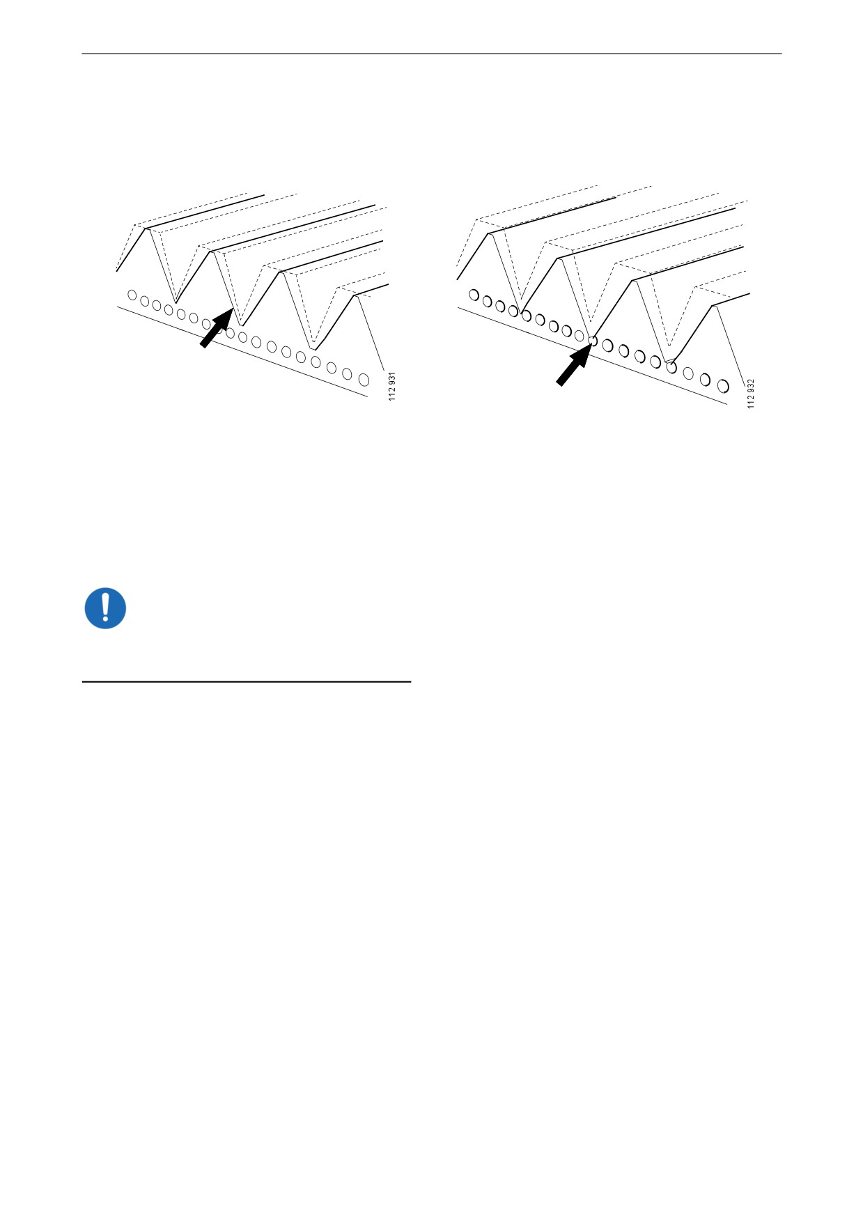
2. Check drive belt wear. Renew the drive belt
if it is too worn.
The drive belt is starting to become worn, but can be
The belt is worn down to the cord. The drive belt
refitted.
must be renewed.
Checking for leaks
IMPORTANT!
If serious leakage occurs, contact your nearest
workshop.
1. Start the engine.
2. Check for oil, coolant, fuel, air or exhaust
leaks.
3. Tighten or renew leaking connections.
Check the overflow holes which show
whether the O-rings between the cylinder
liners and crankcase are leaking.
4. Check whether the drain hole on the coolant
pump is blocked. If there is a leak, renew the
seal in the pump or the complete coolant
pump.
73
Miscellaneous
Checking and adjusting the
valve clearance
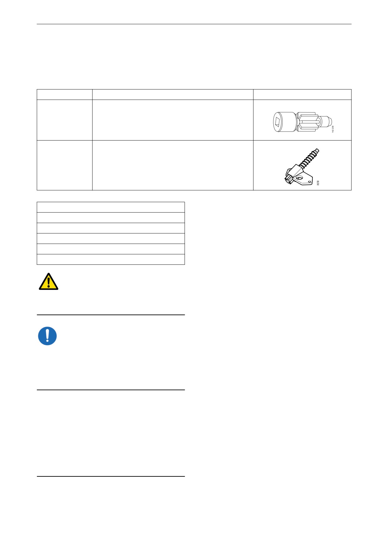
Tool
Number
Description
Illustration
99 309
Turning tool for rotating the flywheel from below
2 402 509
Turning tool for rotating the flywheel from above
Other tools
Torque wrench, 0-50 Nm
Waterproof felt-tip pen
0.45 and 0.70 mm feeler gauges
Flash light
Mirror
WARNING!
Block the starting device. If the engine starts un-
expectedly, there is a serious risk of injury.
IMPORTANT!
The engine must be cold when the work is car-
ried out.
Remember to remove the turning tool from the
flywheel after adjustment.
Note:
Carry out the working without pausing, so that
no step is overlooked.
Carry out a check and adjustment of the valve
clearances one more time after the first 500 hours
of operation. After this, adjustment according to
the regular interval takes place, which is every
2,000 operational hours.
74
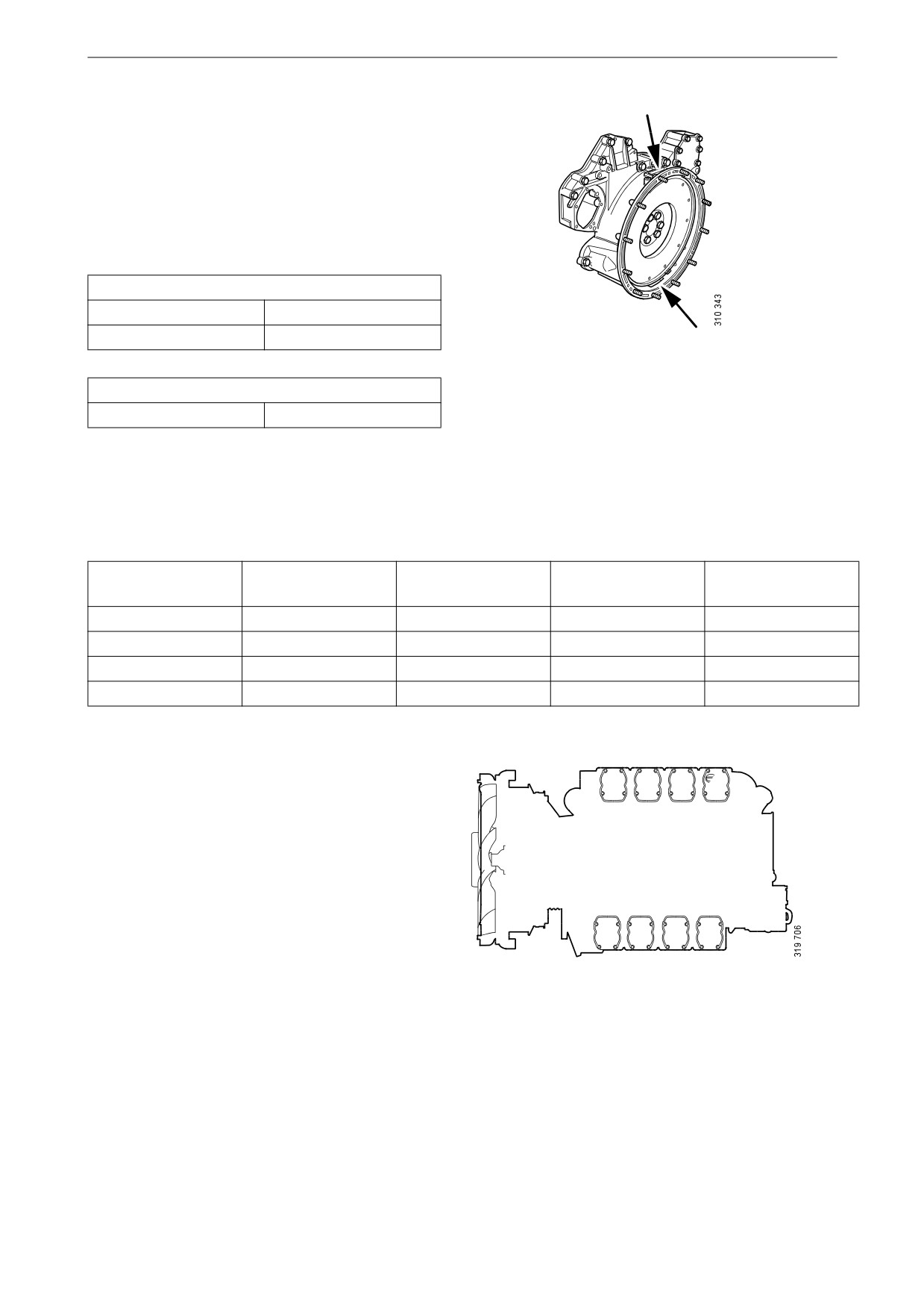
Miscellaneous
On the flywheel is engraved the reference infor-
mation UP TDC, DOWN TDC and the angle in-
dications listed in the table below. Depending on
the engine installation and type of flywheel
housing, this information is visible in one of the
windows, either furthest up or furthest down on
the flywheel. See illustration.
Valve clearance, specifications
Intake valve
0.45 mm (0.018 in)
Exhaust valve
0.70 mm (0.028 in)
Upper and lower window to read the engraving on
the flywheel.
Tightening torque
Lock nut for valves
35 Nm (26 lb/ft)
Adjust valves according to the table below. Fol-
low the respective column depending on whether
you are reading the engraving on the flywheel in
the lower or the upper window. Start adjustment
at the top of the table.
Reading in the low-
Valve transition on
Adjust intake valve
Adjust exhaust
Reading in the up-
er window
cylinder
on cylinder
valve on cylinder
per window
DOWN TDC (0°)
6
7 and 8
4 and 5
UP TDC (180°)
UP TDC (180°)
7
1 and 5
2 and 6
DOWN TDC (0°)
DOWN TDC (360°)
1
2 and 4
3 and 7
UP TDC (540°)
UP TDC (540°)
4
3 and 6
1 and 8
DOWN TDC (360°)
1
2
3
4
5
6
7
8
Order of cylinders.
75

Miscellaneous
1. Clean the rocker covers and the area around
them.
2. Remove the rocker covers.
3. Use the turning tool appropriate to the instal-
lation of the engine. Tool 99 309 is used to
rotate the flywheel from the underside of the
engine and tool 2 402 509 is used from the
top side.
4. Start adjusting one cylinder according to the
table. Rotate the flywheel until the correct
engraving can be read on the flywheel. It
may be necessary to rotate it more than 1 rev-
olution.
Rotate the flywheel in the rotational direc-
tion of the engine, which is clockwise
viewed from the front of the engine and anti-
clockwise viewed from the back of the en-
gine.
During a valve transition, the exhaust valve
(the long arm) is closing at the same time as
the intake valve is opening.
The UP TDC engraving on the flywheel is
now visible in the window furthest up on the
flywheel. The DOWN TDC engraving is vis-
ible in the lower window.
5. Read the table on the previous page to see
which valve to adjust.
6. Stick the feeler gauge under the pressure pad
of the rocker arm and check the valve clear-
ance.
7. If necessary, adjust the valve clearance by
a) loosening the lock nut on the end of the
3
rocker arm
b) adjusting the valve clearance with the ad-
justing screw
c) tightening the lock nut.
4
8. Mark the rocker arm with the felt-tip pen and
then continue with the next cylinder accord-
ing to the table.
5
1. Adjusting screw
2. Lock nut
3. Rocker arm
4. Valve bridge
5. Feeler gauge
76
Miscellaneous
Renewing the reductant filter
1. Wipe clean around the filter housing to pre-
vent impurities from penetrating it.
3
2. Remove the filter housing. Use a 46 mm
socket.
4
WARNING!
There may be a lot of reductant in the filter hous-
5
ing and it may spill out. Wear protective gloves.
1
6
IMPORTANT!
Always rinse away reductant spillage on connec-
tions and other parts with lukewarm water to pre-
vent corrosion. If reductant seeps into electrical
connections or electrical cables, these must be
renewed.
2
3. Remove the sealing diaphragm.
1. Pump
2. Filter
3. Sealing diaphragm
4. O-ring
5. Antifreeze
6. Filter housing
4. Remove the old reductant filter and fit a new
one.
77
Miscellaneous
5. If the anti-freeze protection in the filter hous-
ing comes loose, wipe both the anti-freeze
protection and filter housing thoroughly so
that they are completely dry before they are
assembled again.
6. Wipe the sealing diaphragm and fit it over
the filter.
Ensure that the edge of the diaphragm is sit-
ting in the groove.
7. Lubricate the sealing diaphragm and threads
with the accompanying spray.
78
Miscellaneous
8. Renew the O-ring. Place the new O-ring in
the filter housing.
9. Refit the filter housing. Use a 46 mm socket.
Tighten to 80 Nm (59 lb-ft).
79