Scania DC09 XPI. Industrial engine. Operator’s manual - part 2
Environment and safety
Chemicals
REQUIREMENT!
WARNING!
Use only reductant which fulfils the require-
ments in the Reductant for SCR section.
Most chemicals such as glycol, anti-corrosive
agents, preservative oils and degreasing agents,
are hazardous to health. Some chemicals are also
Safety precautions for maintenance
flammable: preservative oil, for example. Al-
ways follow the safety precautions on the pack-
Switch off the engine
aging.
Store chemicals and other materials which are
WARNING!
hazardous to health in approved and clearly
marked containers, where they are inaccessible
Working with a running engine always poses a
to unauthorised persons.
safety risk. Parts of the body, clothes or dropped
tools can get caught in rotating parts and cause
injury.
Environment
Always switch off the engine before carrying out
Excess and used chemicals must be disposed of
maintenance, unless otherwise indicated.
as specified in national and international laws
and regulations.
Make it impossible to start the engine: Remove
any starter key, or cut the power using the main
power switch or battery master switch and lock
Reductant
them.
Reductant (AdBlue®, DEF, ARLA 32 eller
Fix a warning plate somewhere appropriate,
AUS 32) is used in the reductant tank on engines
showing that work is being carried out on the en-
equipped with an SCR system.
gine.
The reductant is not toxic, but it is still important
Hot surfaces and fluids
to observe the following when working on the re-
ductant circuit:
WARNING!
• If reductant comes in contact with the skin:
Wash with soap and plenty of water.
There is always a risk of sustaining burns when
• If reductant splashes in the eyes: Rinse imme-
an engine is hot. Particularly hot parts are engine
diately using an eye bath and then seek med-
manifolds, turbochargers, oil sumps, as well as
ical attention.
hot coolant and oil in pipes and hoses.
• Change out of clothes which have spills on.
16
Environment and safety
Lubrication system
Environment
WARNING!
Used coolant must be disposed of as specified in
national and international laws and regulations.
Hot oil can cause burns and skin irritation. Wear
protective gloves and goggles when changing
hot oil.
Fuel system
Make sure that there is no pressure in the lubri-
cation system before starting work on it.
WARNING!
Make sure that the oil filler cover is fitted when
starting and running in order to avoid oil escap-
Maintenance and repairs of injection equipment
ing.
are to be carried out by an authorised Scania
workshop.
Always use Scania spare parts for the fuel and
electrical systems. Scania spare parts are de-
Environment
signed to minimise the risk of fire and explosion.
Used oil must be disposed of as specified in na-
tional and international laws and regulations.
Environment
Cooling system
Use a suitable container. The fuel collected must
be disposed of as specified in national and inter-
WARNING!
national laws and regulations.
Never open the coolant filler cap when the en-
gine is hot. Hot coolant and steam may spray out
and cause burns. If the cap has to be opened do it
slowly to release the pressure before removing
the cap. Wear protective gloves as the coolant is
still very hot.
Avoid skin contact with coolant as this may
cause irritation to the skin. Wear protective gog-
gles and gloves when handling coolant.
Ethylene glycol can be fatal if ingested.
17
Environment and safety
Exhaust gas aftertreatment
WARNING!
IMPORTANT!
A P3 type respiratory protection/filter mask,
goggles and gloves should be used for any work
Cleanliness is very important when working on
where there is a risk of exposure to hazardous
the reductant circuit. Clean thoroughly around
particles from the particulate filter. Safety clear-
all parts to be dismantled to prevent dirt from en-
ance for unprotected people is 3 m.
tering the system.
Any particles must be removed with a vacuum
When working on the exhaust gas aftertreatment
cleaner to minimise exposure. The vacuum
management system, the reductant connections
cleaner must be equipped with a HEPA filter that
may only be lubricated with soapy water or with
can filter out particles down to a particle size of
distilled water with a 3% urea mixture. Any oth-
0.3 µm.
er types of lubricants may block and damage the
components in the exhaust gas aftertreatment
To avoid ingestion, do not eat, drink or smoke
management system.
while work is in progress. Make sure you clean
your hands after working on the particulate filter.
Reductant causes certain metals to corrode. Al-
ways rinse away reductant spillage on connec-
tions and other parts with lukewarm water to
prevent corrosion. If reductant seeps into electri-
Environment
cal connections or electrical cables, these must
be renewed.
The oxidation catalytic converter, the particulate
filter and the SCR catalytic converter contain
precious metals and must be processed in com-
pliance with local regulations.
WARNING!
When the engine is running, the exhaust system
parts can reach such high temperatures that there
is a risk of personal injury. Make sure that the
temperature has fallen to a suitable level before
starting work.
18
Environment and safety
Electrical system
Batteries
WARNING!
WARNING!
Switch off the engine and switch off the power
The batteries contain highly corrosive sulphuric
by disconnecting the electrical cables to the bat-
acid. Take care to protect your eyes, skin and
tery. External power supplies to extra equipment
clothes when charging or handling batteries.
on the engine must also be disconnected.
Wear protective gloves and goggles.
Always use Scania spare parts for the fuel and
If sulphuric acid comes in contact with the skin:
electrical systems. Scania spare parts are de-
Wash with soap and plenty of water. If it gets in
signed to minimise the risk of fire and explosion.
your eyes: Rinse immediately with plenty of wa-
ter and seek medical attention.
Electric welding
Environment
WARNING!
Used batteries must be disposed of as specified
When carrying out welding work on and near the
in national and international laws and regula-
engine, disconnect the battery and alternator
tions.
leads. Pull out the multi-pin connector for the en-
gine control unit as well.
Before starting
Connect the welding clamp close to the compo-
nent to be welded. The welding clamp must not
WARNING!
be connected to the engine, or so that the current
can cross a bearing.
Ensure that all guards are in place before starting
the engine. Ensure that no tools or other objects
When welding is finished:
have been left on the engine.
1. Connect the alternator and engine control
The air filter must be fitted before starting the en-
unit cables.
gine. Otherwise there is a risk of objects being
2. Connect the batteries.
sucked into the compressor impeller or of injury
if you come into contact with the air filter.
19
Engine data plate
Engine data plate
The engine data plate indicates, in the form of a
code, the engine type, its size and applications. It
also indicates the engine type power range and
the nominal engine speed. The engine EU type
approval for exhaust emissions is indicated un-
der Output, where applicable.
The engine power is stated on a plate which is lo-
cated on the engine control unit. The engine seri-
al number is stamped onto the top of the cylinder
block at the front right.
Example: DC09 085A
Made b y
DC Supercharged diesel engine with air-
cooled charge air cooler.
Type
DC09 085A
09
Displacement in whole dm3.
Engine No
6950106
Output.
232-257
kW
2100
r pm.
085
Performance and certification code. The
code indicates, together with the applica-
tion code, the normal gross engine output.
A
Code for application. A means for general
industrial use.
Example of an engine data plate.
20
Component identification
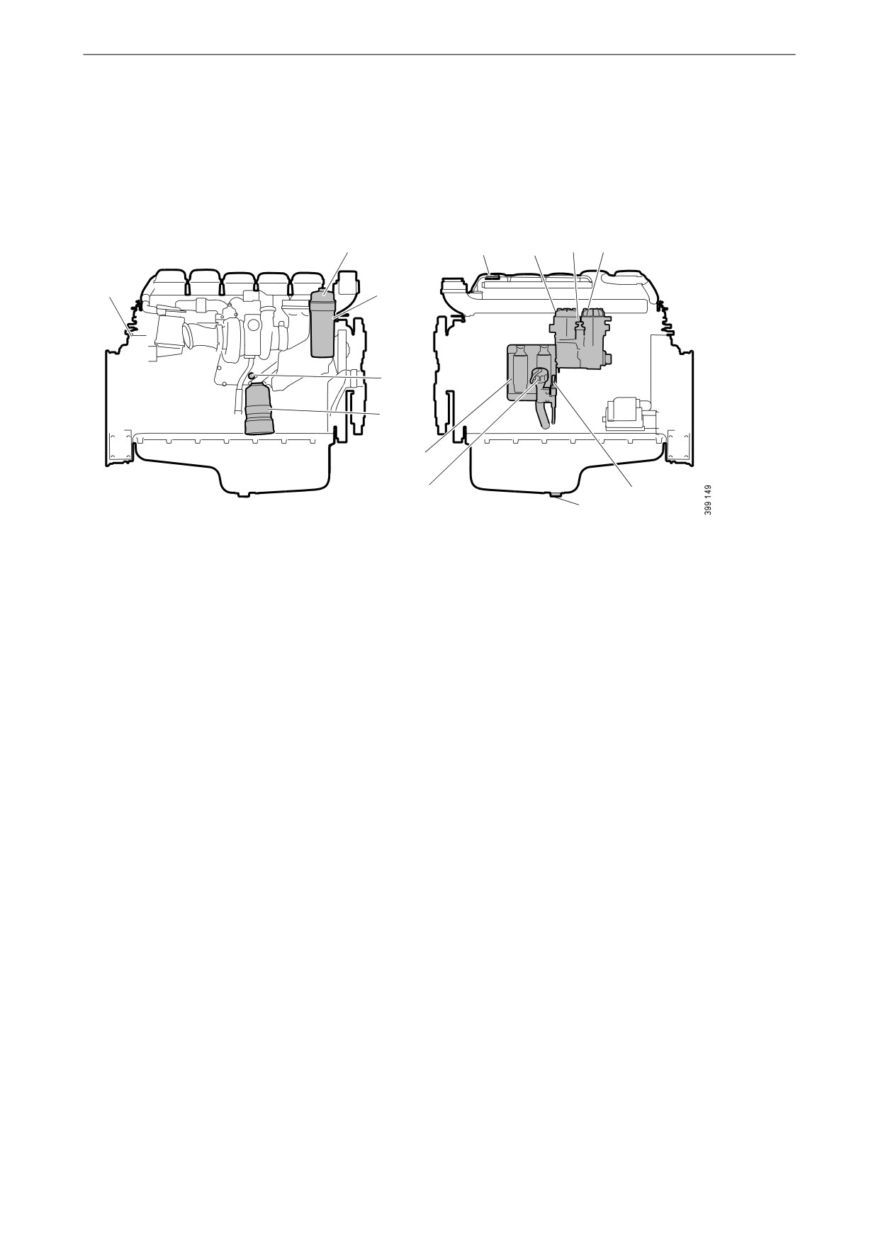
Component identification
Engine
2
6
7
8
9
1
3
4
5
12
6
10
11
The illustration shows a normal version of a DC09 engine. The engine ordered may have different equipment.
1. Engine data plate
2. Oil filter
3. Engine serial number, stamped into the cylinder block
4. Nipple for draining and filling coolant
5. Centrifugal oil cleaner
6. Oil filler
7. Water separating prefilter for fuel
8. Hand pump for fuel
9. Fuel filter
10. Oil dipstick
11. Oil plug
12. Engine control unit
21
Component identification
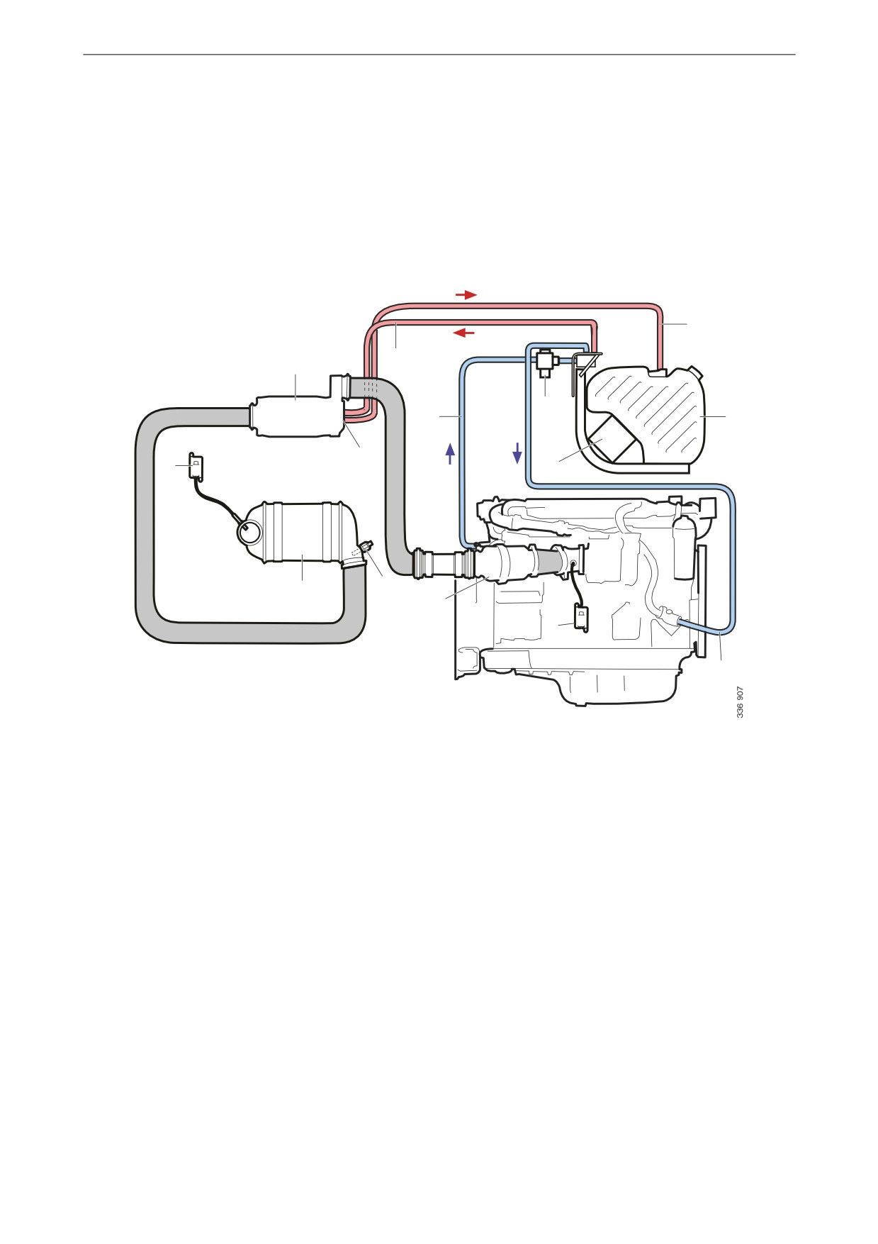
Exhaust gas aftertreatment
management system
Stage IV/Tier 4f and Stage IIIB/Tier 4i
The illustration provides an overview of exhaust
gas aftertreatment management system compo-
nents.
5
2
1
4
3
6
14
13
7
11
12
10
9
8
1. Evaporator
8. Coolant hose, return from tank and pump heating
2. Pressure line for reductant
9. NOx sensor with control unit1
3. Coolant hose for tank and pump heating
10. Oxidation catalytic converter1
4. Coolant valve
11. Exhaust gas temperature sensor
5. Reductant return line
12. SCR catalytic converter
6. Reductant tank
13. NOx sensor with control unit
7. Reductant pump and control unit
14. Reductant doser
1. DC09 084/384/085/385/086/386/087/387/089/389A only.
22

Component identification
Stage V
The illustration provides an overview of exhaust
gas aftertreatment management system compo-
nents.
13
12
9
10
11
8
16
14
15
7
6
5
1
2
3
4
1. NOx sensor with control unit
9. NOx sensor with control unit
2. Differential pressure sensor
10. SCR catalytic converter
3. Exhaust gas temperature sensor
11. Evaporator
4. Exhaust gas temperature sensor
12. Reductant return line
5. Oxidation catalytic converter
13. Pressure line for reductant
6. Particulate filter
14. Reductant tank
7. Exhaust gas temperature sensor
15. Coolant hose for tank and pump heating
8. Reductant doser
16. Coolant hose, return from tank and pump heating
23

Starting and running
Starting and running
1
Checks before first start
Before the engine is started for the first time, car-
ry out the maintenance items listed under First
start in the maintenance schedule. Check the fol-
lowing:
• Oil level.
• Coolant.
• Fuel level.
2
• Fluid level in batteries.
• State of battery charge.
• Condition of the drive belt.
• Level in the reductant tank, if the engine is
equipped with an SCR system.
See also Maintenance intervals.
IMPORTANT!
Running the engine without reductant in the re-
3
ductant tank violates emissions legislation and
will damage the SCR system.
Reductant tank
Reductant tanks come in 5 different sizes. The
volumes indicated for each tank are filling vol-
umes.
1. 38 litres (10 US gallons).
4
2. 60 litres (15.8 US gallons).
3. 45 litres (11.9 US gallons).
4. 63 litres (16.6 US gallons).
5. 70 litres (18.5 US gallons).
A filler filter with magnet is fitted in the reduct-
ant tank to prevent the reductant from becoming
contaminated when topping up. It is used when
refuelling at a filling station. A filler filter with-
out a magnet is also supplied for use when filling
manually.
5
24

Starting and running
Reductant pump
When the reductant pump is new, the check
valves may need to be slackened.
IMPORTANT!
Blow the reductant pump suction nipple with
compressed air (approx. 6 bar/87 psi) for at least
3 seconds before starting the engine for the first
time.
Start the reductant pump immediately after the
reductant tank has been filled for the first time.
Reductant pump suction nipple
Checks before running
Carry out daily maintenance as described in the
maintenance schedule prior to operation. See
Maintenance intervals.
25
Starting and running
Starting the engine
Starting at low temperatures and at
high altitudes
Take the local environmental requirements into
WARNING!
account. Use a fuel heater and engine heater to
avoid starting problems and white smoke.
Never use starter gas or similar agents to help
start the engine. This can cause an explosion in
Scania recommends that an engine heater should
the intake manifold and possible injury.
be used if the engine will be used at temperatures
below -10°C (14°F) or at an altitude of more than
Only start the engine in a well ventilated area.
2,000 metres.
When the engine is run in an enclosed space,
there must be effective devices to extract exhaust
A low engine speed and a moderate load on a
gases and crankcase gases.
cold engine limits white smoke, gives better
combustion and warms up the engine more
quickly than warming it up with no load.
IMPORTANT!
Avoid running it longer than necessary at idling
speed.
The starter motor must only be cranked twice for
30 seconds at a time. After that, it must rest for at
Running
least 5 minutes before the next attempt to start it.
Check instruments and warning lamps at regular
intervals.
For environmental reasons the Scania engine has
been developed to be started with a low fuel feed.
Engine speed range
Using unnecessarily large amounts of fuel when
The engine operating speed range is between low
starting the engine always results in emissions of
idling and the nominal engine speed. The nomi-
unburnt fuel.
nal engine speed is indicated on the engine data
plate. Low idling can be set between 500 and 975
1. Open the fuel cock if fitted.
rpm.
2. Disengage the engine.
A slightly higher engine speed than the nominal
3. If the engine has a battery master switch:
engine speed may occur at low or negative load.
Connect the power using the battery master
switch.
Driving at high altitude
4. Start the engine.
When driving at high altitudes engine power is
If the fuel tank has been run dry or if the engine
reduced automatically due to the lower oxygen
has not been used for a long time, bleed the fuel
content in the air. It is then not possible to run the
system. See the section Bleeding the fuel system.
engine at maximum power.
Note:
Driving at an altitude higher than 4,000 metres
above sea level is only permitted if it has first
been approved by Scania.
With high dynamic operation
Note:
In machines with high dynamic operation, for
example excavators, the EGR cooler may need
cleaning. Cleaning must be carried out as de-
scribed in the Workshop Manual.
26
Starting and running
Emission control
The system provides a warning if there are faults
on the SCR system or if the level of reductant in
the reductant tank is too low. In the case of some
faults, for example if doser cooling is not work-
ing, the torque is reduced.
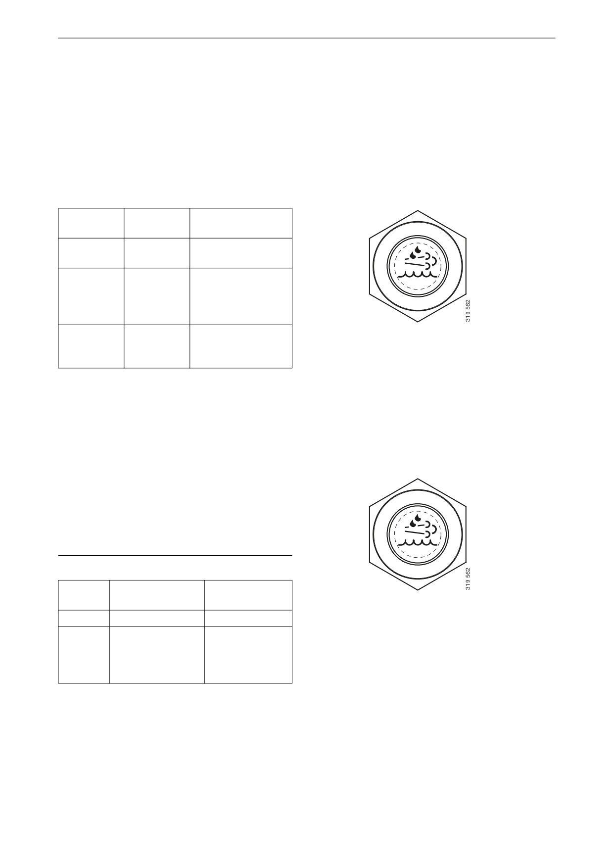
Reaction at low reductant level - Stage
IIIB/IV/Tier 4i/Tier 4f
Reductant
Warning
Torque reduction1
level
lamp
20%
Constant
light
10%
Flashing
Torque is reduced by
1% per minute to
70% of the highest
torque
0%
Flashing rap-
Torque is reduced to
Symbol for low reductant level
idly
0% (low idling)
within 2-10 minutes
1. Applies only to engines that are certified according to
Tier 4.
The engine resumes normal torque after reduct-
ant has been filled to a level of at least 20%.
Reaction at low reductant level - Stage V
Note:
Its behaviour and the symbol depend on the in-
stallation of the engine in the machine. The Sca-
nia recommendation will lead to the behaviour
and symbol described here, but this may differ
between different machines.
Level
Warning lamp
Torque and
speed control
Symbol for low reductant level
10%
Constant light
-
2.5%
Flashes slowly
Torque is reduced
(½ Hz)
by 1% per minute
to 75% of the
highest torque.
27
Starting and running
Level
Warning lamp
Torque and
speed control
0%
Flashes rapidly
Torque is reduced
(2 Hz)
by 1% per minute
to 50% of the
highest torque.
The engine speed
is reduced to 60%
of the nominal en-
gine speed.
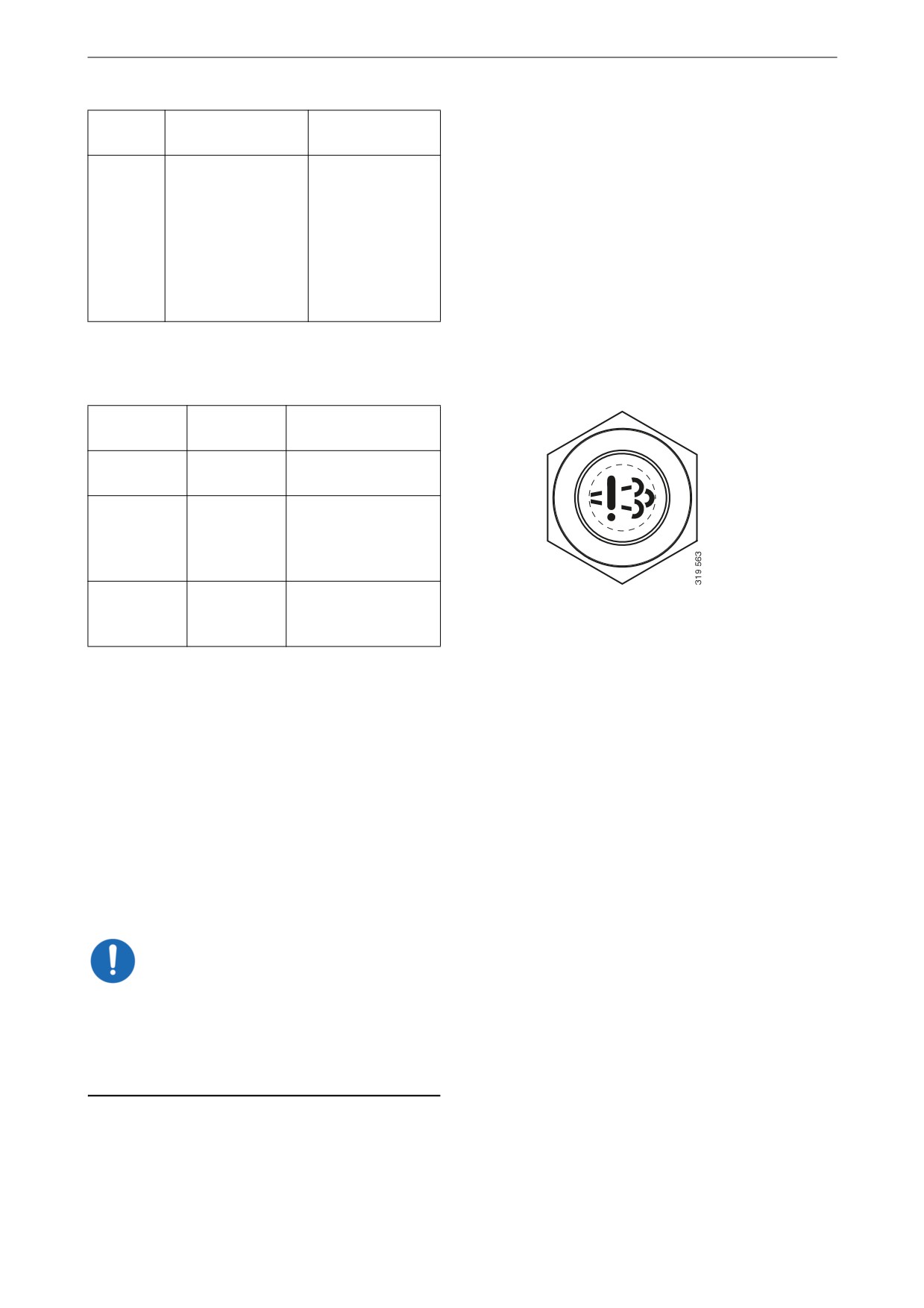
Reaction to fault in the SCR system -
Stage IIIB/IV/Tier 4i/Tier 4f
Time
Warning
Torque reduction1
lamp
Fault detect-
Constant
ed
light
After 30
Flashing
Torque is reduced by
minutes
1% per minute to
70% of the highest
torque
After 4 hours
Flashing rap-
Torque is reduced to
Symbol for fault in SCR system
idly
0% (low idling)
within 2-10 minutes
1. Applies only to engines that are certified according to
Tier 4.
If a new fault occurs within 40 hours of opera-
tion since the first fault, the warning lamp will
come on. After 30 minutes of operation, the
warning lamp will flash rapidly and torque will
be reduced to 0% (low idling) within 30 minutes.
Once the fault has been remedied and the engine
control unit has received an indication that the
exhaust gas aftertreatment management system
is operating i.e. when the fault code has been ac-
knowledged in SDP3, torque returns to the nor-
mal level.
IMPORTANT!
If the torque has been reduced to 0% (low
idling), the control unit does not detect that the
SCR system is functioning again. A service tech-
nician must then reset the system so that the
torque returns to the normal level.
28

Starting and running
Note:
The torque reduction applies only to engines cer-
tified according to Tier 4. Some emergency vehi-
cles do not have torque reduction.
Reaction to fault in the exhaust gas after-
treatment system - Stage V
Note:
The symbol and behaviour of the warning lamp
depend on the installation of the engine in the
machine. The Scania recommendation will lead
to the behaviour and symbol described here, but
this may differ between different machines.
Warning
Torque and speed control
lamp
Symbol for faults in the exhaust gas aftertreatment
Constant
None
system
light
Flashes
Torque is reduced by 1% per minute
slowly
to 75% of the highest torque.
(½ Hz)
Flashes rap-
Torque is reduced by 1% per minute
idly (2 Hz)
to 50% of the highest torque. The
engine speed is reduced to 60% of
the nominal engine speed.
Once the fault has been remedied and the engine
control unit has received an indication that the
exhaust gas aftertreatment management system
is operating i.e. when the fault code has been ac-
knowledged in SDP3, torque returns to the nor-
mal level.
Regeneration of the particulate filter
The particulate filter is regenerated, i.e. cleaned,
automatically. If a certain amount of soot is ac-
cumulated, the engine enters a periodic and auto-
matic program to reduce the amount of soot. The
engine can be used without any impact on oper-
ation.
However, if the particulate filter becomes full, it
Symbol for the particulate filter
must be regenerated manually. The engine can-
not be used for approximately 45 minutes while
manual regeneration is carried out. The particu-
late filter symbol is used to indicate that the par-
ticulate filter is full and needs to be regenerated
manually.
29

Starting and running
With manual regeneration, the engine speed can
rise to 1,500 rpm for all-speed engines and with
engines configured for single-speed, all regener-
ation occurs at the selected rotational speed.
Note:
The symbol and behaviour of the warning lamp
depend on the installation of the engine in the
machine. The Scania recommendation will lead
to the behaviour and symbol described here, but
this may differ between different machines.
Warning lamp
Description
Constant light
The particulate filter is starting
to become full. Increase the
load to improve automatic re-
generation or regenerate the
particulate filter manually.
Flashes slowly
Carry out manual regeneration
(½ Hz)
as soon as possible.
Flashes rapidly
The particulate filter is over-
(2 Hz)
full. Manual regeneration can
only be carried out using
SDP3.
30
Starting and running
Coolant temperature
IMPORTANT!
An excessive coolant temperature can cause en-
gine damage.
Normal coolant temperature during operation is
90 to 95°C (194 to 203°F).
The alarm levels are set in the engine control
unit. The default setting for the lowest and high-
est limit values for high coolant temperature are
95 °C (203 °F) and 105°C (221°F) respectively.
The following function is standard as alarm for
high coolant temperature:
• Alarm and torque reduction at the lowest lim-
it value.
Depending on the engine configuration, the fol-
lowing alarm functions may also be available:
• Alarm only.
• Alarm and engine shutdown at the highest
limit value.
• Alarm, torque reduction at the lowest limit
value and engine shutdown at the highest lim-
it value.
• Alarm and engine shutdown at the highest
limit value with the possibility of engine shut-
down override control.
• Alarm, torque reduction at the lowest limit
value and engine shutdown at the highest lim-
it value, with the possibility of engine shut-
down override control.
If run for extended periods under an extremely
light load, the engine may have difficulty in
maintaining the coolant temperature. At an in-
creased load the coolant temperature rises to the
normal value.
31