Scania OC16 Gas. Industrial engine. Operator’s manual - part 3
Lubrication system
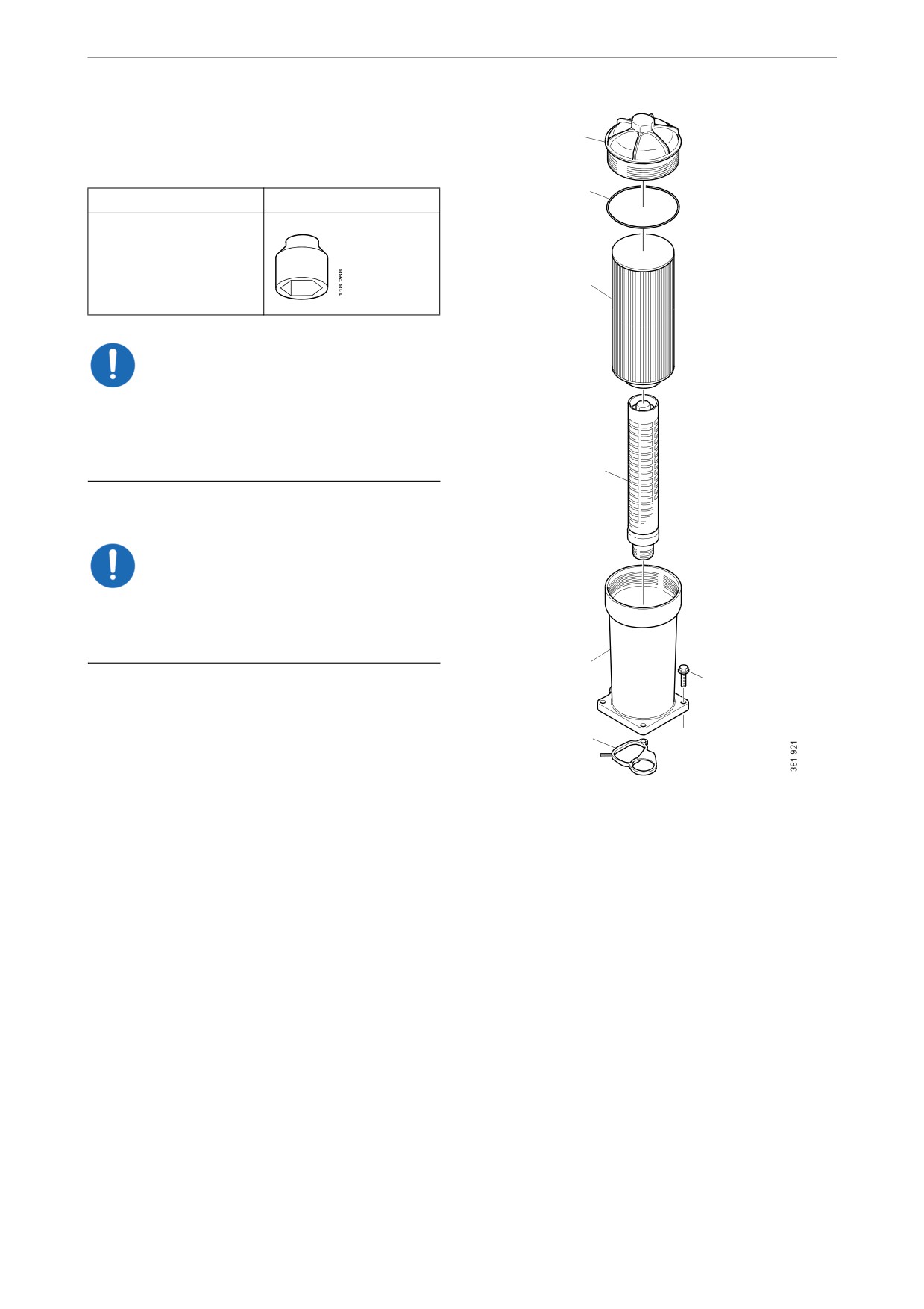
Renewing the oil filter
1
Tool
2
Designation
Illustration
Hexagon socket, 1/2",
36 mm
3
IMPORTANT!
The engine must not be run without a filter ele-
ment in the oil filter. There is a risk of engine
damage caused by particles and by the oil pres-
sure being too low.
4
1. Unscrew the filter cover using the socket.
IMPORTANT!
Do not use an adjustable spanner or other open
tool, as there is a risk of damaging the filter cov-
er.
5
6
2. Lift out the filter housing cover with filter el-
ement. The filter housing will drain automat-
ically once the filter has been removed.
7
3. Undo the old filter from the cover by careful-
ly bending it to one side.
1.
Cover.
4. Fit a new O-ring on the cover. Lubricate the
O-ring with engine oil.
2.
O-ring.
3.
Filter element.
5. Press a new filter into the snap fastener in the
4.
Pipe.
cover and tighten the filter cover to 25 Nm
5.
Filter housing.
(18 lbf/ft).
6.
Flange screw.
6. Make sure the oil filter drain has emptied the
7.
Gasket.
oil from the filter housing. Screw on the filter
cover firmly with the socket.
7. Start the engine and inspect the filter housing
for leaks.
32
Air cleaner
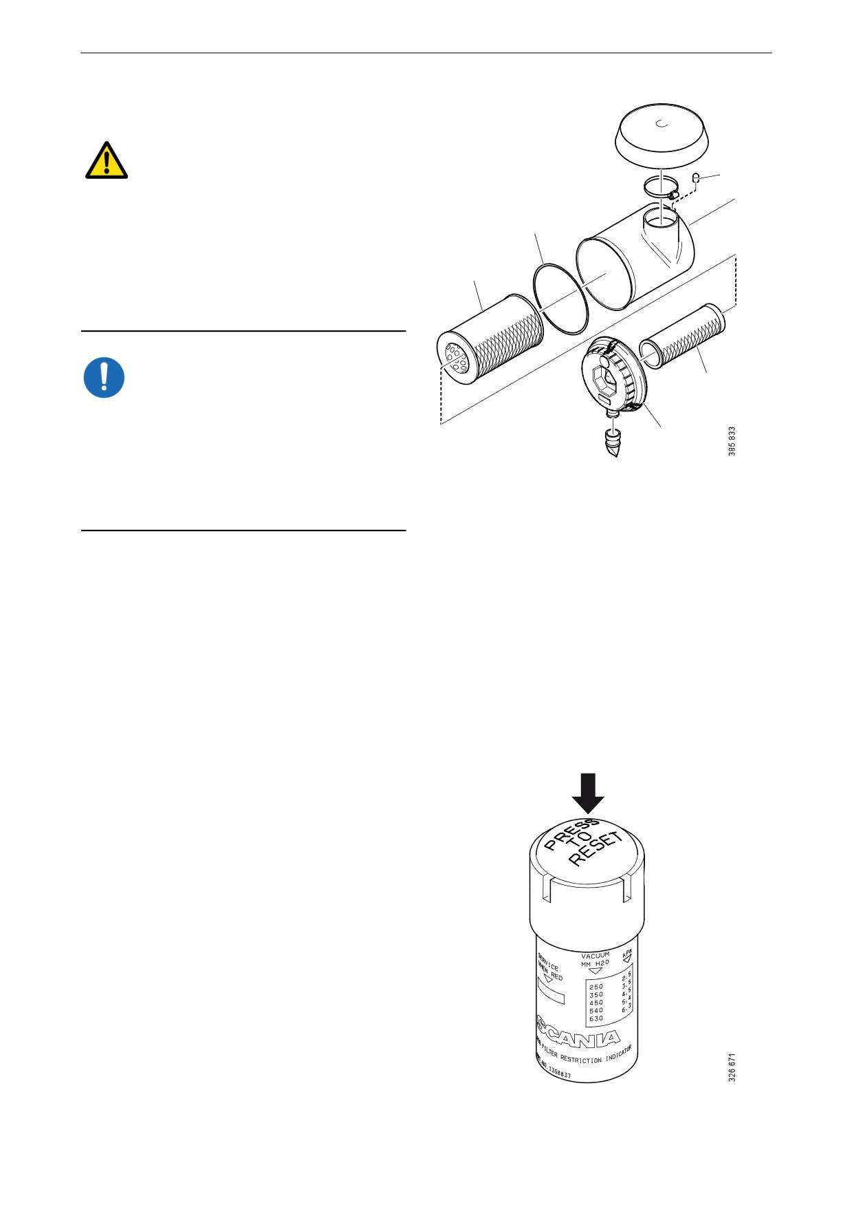
Air cleaner
WARNING!
3
Never start the engine without the air filter in po-
sition. Without the air filter, there is a risk of dirt
2
being sucked into the engine.
The engine turbocharger will continue to rotate
1
and take in air for a time, even after the engine
has stopped. Therefore, wait for a few minutes
before opening the air cleaner.
IMPORTANT!
4
Renew the filter element earlier than the mainte-
nance interval if the vacuum indicator shows red.
5
The filter element must not be cleaned in water
or be blown clean with compressed air. There is
Air cleaner with safety cartridge.
always a risk that the filter element will be dam-
1.
Filter element.
aged when it is cleaned.
2.
O-ring.
3.
Vacuum indicator.
4.
Safety cartridge.
5.
Cover.
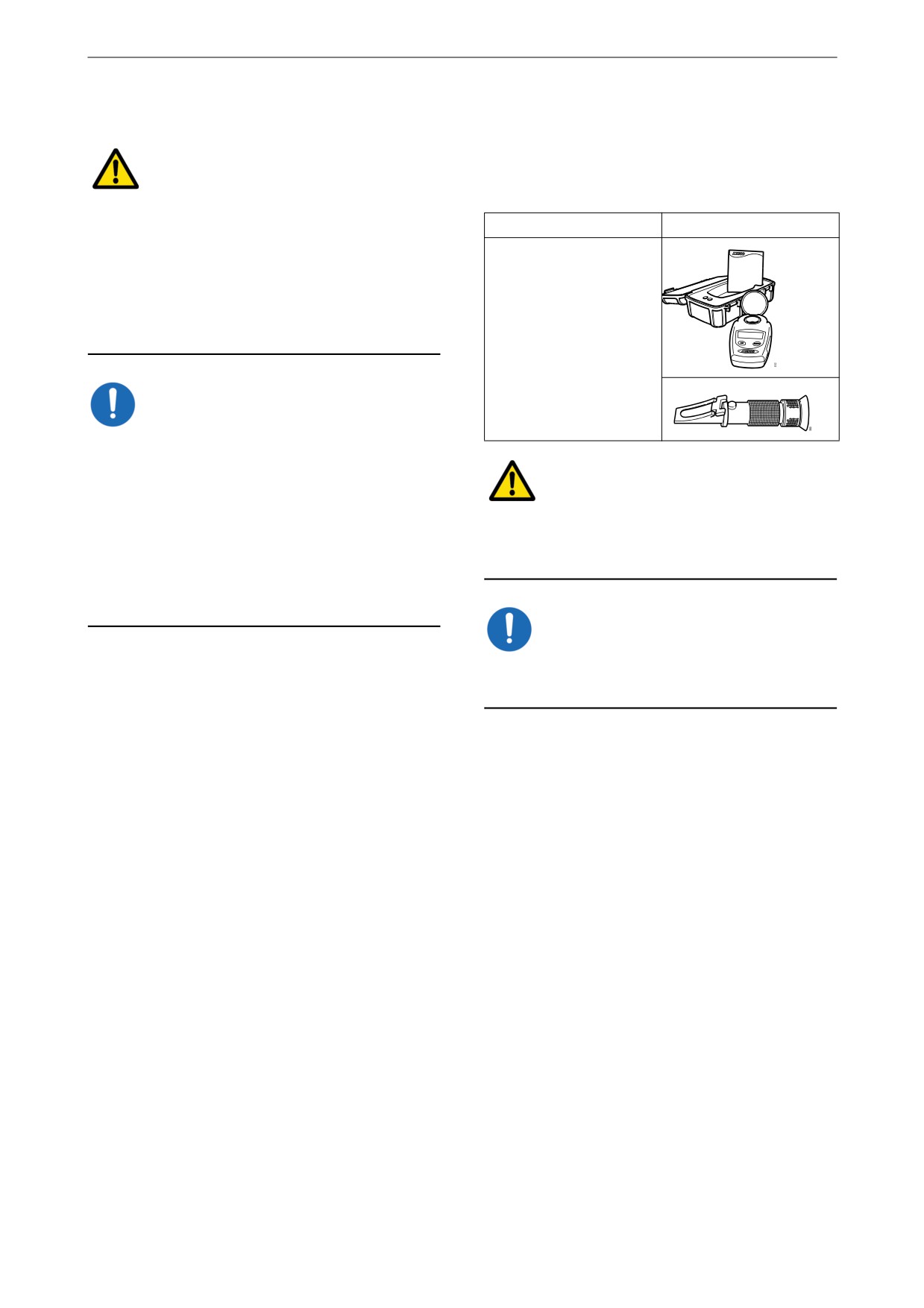
Reading the vacuum indicator
If the vacuum indicator's red plunger is fully vis-
ible, renew the air cleaner filter element in ac-
cordance with the following section.
Renewing the filter element
and safety cartridge
1. Remove the cover from the air cleaner.
2. Renew the filter element.
3. Remove the safety cartridge and fit a new
one.
4. Insert a torch into the filter element and
check that the filter paper is free of holes and
cracks.
5. Renew the O-ring if it is damaged or hard.
6. Assemble the air cleaner.
7. Ensure that the O-ring is not outside the edg-
es.
8. Reset the vacuum indicator by pressing in
the button marked in the illustration.
33
Cooling system
Antifreeze and corrosion protection
Cooling system
The antifreeze and corrosion protection used in
Scania engines should be antifreeze (ethylene
Coolant
glycol) and corrosion inhibitor.
Note:
Only Scania coolant or another product with
The coolant should be changed when the cooling
functioning antifreeze and corrosion protection
system is cleaned: every 6,000 hours or at least
may be used in Scania engines. Products not ful-
every 5 years. See Changing the coolant and
filling the demands in this section may lead to
cleaning the cooling system.
faults and damage occurring in the cooling sys-
tem. This can lead to the invalidation of Scania's
warranty for faults and damage caused by the use
The coolant recommended by Scania is a mix-
of inappropriate coolant.
ture of water with antifreeze (ethylene glycol)
and corrosion inhibitor. The coolant has several
Addition of antifreeze and corrosion
characteristics which are important for the oper-
inhibitor to water
ation of the cooling system:
The coolant should contain 35-55% by volume
• Corrosion inhibitor.
antifreeze (ethylene glycol) and corrosion inhib-
itor. The percentage varies depending on the
• Antifreeze.
need for antifreeze.
• Increases the boiling point.
A minimum of 35% by volume of Scania anti-
Water
freeze and corrosion inhibitor is needed to pro-
vide sufficient protection against corrosion.
Use only pure fresh water that is free from parti-
cles, sludge and other impurities. If there is un-
Note:
certainty about the quality of the water, Scania
Too high a dose of antifreeze and corrosion in-
recommends use of Scania ready-mixed cool-
hibitor will increase the amount of sludge and
ants. See the section Recommended Scania prod-
blockages accumulating in the radiator. Too low
ucts.
a concentration can lead to corrosion of the cool-
ing system and ice formation at low tempera-
tures.
Measure the ethylene glycol content (antifreeze
and corrosion protection) with a refractometer
following the instructions in the Checking cool-
ant antifreeze and corrosion protection section.
34

Cooling system
Risk of freezing
IMPORTANT!
The engine should not be subjected to heavy
loads when ice starts to build up in the cooling
system.
As the coolant starts to freeze, the water in the
coolant starts to crystallise and the percentage of
ethylene glycol in the coolant therefore rises. If
freezing produces a great increase in the amount
of ice, circulation problems could arise. There is
no risk of damage by freezing if the content of
Scania antifreeze and corrosion inhibitor, or an
equivalent mixture of a similar product, is at
least 35% by volume.
Minimal ice formation in the coolant sometimes
causes minor problems without any risk of dam-
age. For example, the auxiliary heater may not
work for up to 1 hour after the engine has been
started.
10
20
30
40
50
60%
The chart depicts coolant properties at different
o
percents of antifreeze and corrosion inhibitor
-10
C
concentration by volume.
o
-16
C
1
o
-20
C
Curve A: Ice formation starts (ice slush)
o
-30
C
Curve B: Damage by freezing
3
2
o
Area 1: Safe range
-40
C
Area 2: Malfunctions may occur (ice
o
-50
C
slush)
o
Area 3: Risk of damage by freezing
-60
C
B
A
The following example shows coolant properties
with 30 percent by volume of antifreeze and cor-
rosion inhibitor:
• Ice slush starts to form at -16°C (3°F).
• At -30°C (-22°F), there is a risk of cooling
system malfunction.
• There is no risk of damage by freezing with a
minimum antifreeze and corrosion inhibitor
content of 35 percent by volume.
Example: If the temperature is -16 C (3°F), there
is a risk of damage by freezing if the percentage
of antifreeze and corrosion inhibitor is 20% by
volume. At 30% antifreeze and corrosion protec-
tion by volume the coolant will not contain any
ice.
35

Cooling system
Warm climates
Recommended Scania products
In order to retain the corrosion protection and the
Scania Ready Mix 50/50
higher boiling point, it is essential to use coolant
consisting of water mixed with antifreeze and
Scania Ready Mix 50/50 is a ready-mixed cool-
corrosion inhibitor (ethylene glycol). This also
ant containing 50% antifreeze (ethylene glycol)
applies in countries where the temperature never
and corrosion protection and 50% water. It
drops below 0°C (32°F).
should be used in cold countries where there is a
risk of freezing in the cooling system.
The coolant should always contain 35-55% by
volume of antifreeze and corrosion inhibitor so
that the coolant properties ensure that the coolant
Part No.
Volume
Volume
works correctly.
litres
US gallons
1 921 955
5
1.3
Topping up
1 921 956
20
5.3
Coolant must only be topped up with pre-mixed
coolant. The pre-mixed coolant can either be
1 921 957
210
55
concentrate mixed with clean freshwater or pre-
1 896 695
1,000
264
mixed coolant from the factory. Use only pure
fresh water that is free from particles, sludge and
Scania Ready Mix 35/65
other impurities.
Scania Ready Mix 35/65 is a ready-mixed cool-
ant containing 35 % antifreeze (ethylene glycol)
IMPORTANT!
and corrosion protection and 65 % water. It
should be used in warm countries where there is
no risk of freezing in the cooling system.
Containers, which are used for mixing coolant,
must be intended for the purpose and free from
any dirt or contaminants. When the containers
Part No.
Volume
Volume
not in use they must be kept closed to avoid col-
litres
US gallons
lecting dirt and dust.
2 186 291
5
1.3
2 186 292
20
5.3
Note:
2 186 293
210
55
Within the coolant change interval, coolant may
2 186 294
1,000
264
only be reused if it has been cleaned of dirt,
sludge and particles. If the coolant is contaminat-
Scania concentrate
ed with oil or fuel, it must not be reused.
Scania also produces coolant with antifreeze and
corrosion inhibitor in the form of a concentrate.
Part No.
Volume
Volume
litres
US gallons
1 894 323
5
1.3
1 894 324
20
5.3
1 894 325
210
55
1 894 326
1,000
264
36

Cooling system
Antifreeze and corrosion protection
dosing
35% by volume of Scania antifreeze provides
sufficient protection against corrosion. The low-
er the temperature, the higher the anti-freeze
content required. In the tables below, you can see
how much antifreeze is required in litres and US
gallons at different temperatures.
Example, US gallons:
Example, litres:
• The total volume of the cooling system is 18
• The total volume of the cooling system is 68
US gallons.
litres.
• The measured concentration of ethylene gly-
• The measured concentration of ethylene gly-
col is 35% by volume (freezing point -6 °F).
col is 35% by volume (freezing point -21°C).
According to the table there are
According to the table there are 25 litres of
6.6 US gallons of ethylene glycol in the cool-
ethylene glycol in the cooling system.
ing system.
• The required concentration of ethylene glycol
• The required concentration of ethylene glycol
is 45% by volume (freezing point -30°C). Ac-
is 45% by volume (freezing point -22 °F). Ac-
cording to the table, 32 litres of ethylene gly-
cording to the table, 8.5 US gallons of ethyl-
col are required in the cooling system.
ene glycol are required in the cooling system.
• Since there are already 25 litres in the cooling
• Since the cooling system already contains
system, fill another 7 litres of ethylene glycol
6.6 US gallons, fill with another
(32 - 25 = 7 litres).
1.9 US gallons of ethylene glycol (8.5 -
6.6 = 1.9 US gallons).
Ethylene glycol con-
tent (%)
35
40
45
50
60
Ethylene glycol con-
tent (%)
35
40
45
50
60
Ice slush forms (°C)
-21
-24
-30
-38
-50
Ice slush forms (°F)
-6
-11
-22
-36
-58
Volume of ethylene
25
28
32
35
42
glycol (litres)
Volume of ethylene
6.6
7.4
8.5
9.2
11.
glycol (US gallons)
1
37
Cooling system
Checking coolant level
Checking coolant antifreeze
and corrosion protection
WARNING!
Tool
Do not open the coolant filler cap in the expan-
sion tank if the engine is hot. Hot coolant and
Designation
Illustration
steam may spray out and cause burns. If the cap
Refractometer
has to be opened do it slowly to release the pres-
sure before removing the cap.
Use protective gloves as coolant can cause irrita-
tion if it comes in contact with the skin.
IMPORTANT!
It is not permissible to top up large amounts of
coolant via the expansion tank. Filling via the ex-
pansion tank leads to air locks in the cooling sys-
WARNING!
tem which can lead to e.g. cavitation damage to
the coolant pump shaft seal. If a large amount of
Avoid skin contact with coolant as this may
coolant needs to be added, follow the instruc-
cause irritation to the skin. Wear protective gog-
tions in the section Filling coolant.
gles and gloves when handling coolant.
Only pour pre-mixed coolant into the cooling
system.
IMPORTANT!
The following instructions apply to Scania ex-
Use only pure fresh water that is free from parti-
pansion tanks. For other types of expansion
cles, sludge and other impurities.
tanks, follow the manufacturer's instructions.
1. Open the expansion tank cap and check the
1. Pour a small amount of coolant into a con-
coolant level.
tainer and check that the coolant is pure and
- The right coolant level on a cold engine is
clear.
even with the lower edge of the filler neck.
2. Change the coolant if it is contaminated or
- The right coolant level on a hot engine is
cloudy.
approximately 25 mm (1 in) over the low-
er edge of the filler neck.
3. Measure the antifreeze and corrosion inhibi-
tor content with the refractometer.
2. Top up with coolant as necessary.
The following rules apply to ethylene glycol-
based coolant:
• The antifreeze and corrosion inhibitor content
must be minimum 35 percent by volume for
corrosion protection to be sufficient.
• An antifreeze and corrosion inhibitor content
greater than 55 percent by volume impairs the
ability to protect against frost.
• If ice forms in the coolant, there are disrup-
tions initially, but there is no immediate risk
of damage. The engine should not be subject-
ed to heavy loads when ice starts to form.
38
Cooling system
Changing the coolant and
cleaning the cooling system
Draining coolant
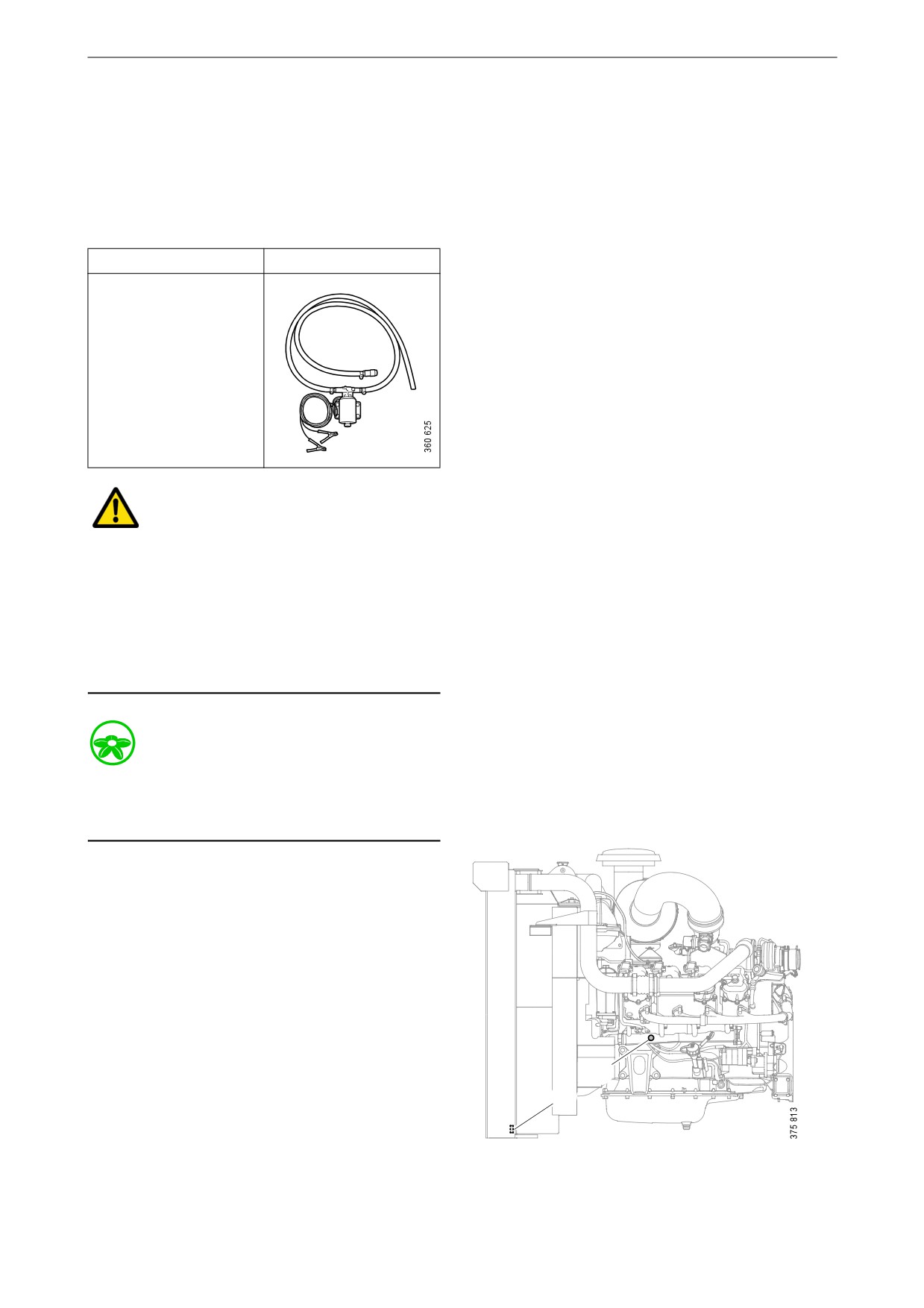
Special tools
Number, designation
Illustration
2 443 679, coolant
pump
WARNING!
Do not open the coolant filler cap in the expan-
sion tank if the engine is hot. Hot coolant and
steam may spray out and cause burns. If the cap
has to be opened do it slowly to release the pres-
sure before removing the cap.
Use protective gloves as coolant can cause irrita-
tion if it comes in contact with the skin.
Environment
Use a suitable container. Used coolant must be
disposed of as specified in national and interna-
tional laws and regulations.
1. Open the expansion tank cap.
2. Position the hose from the coolant pump in
an empty container.
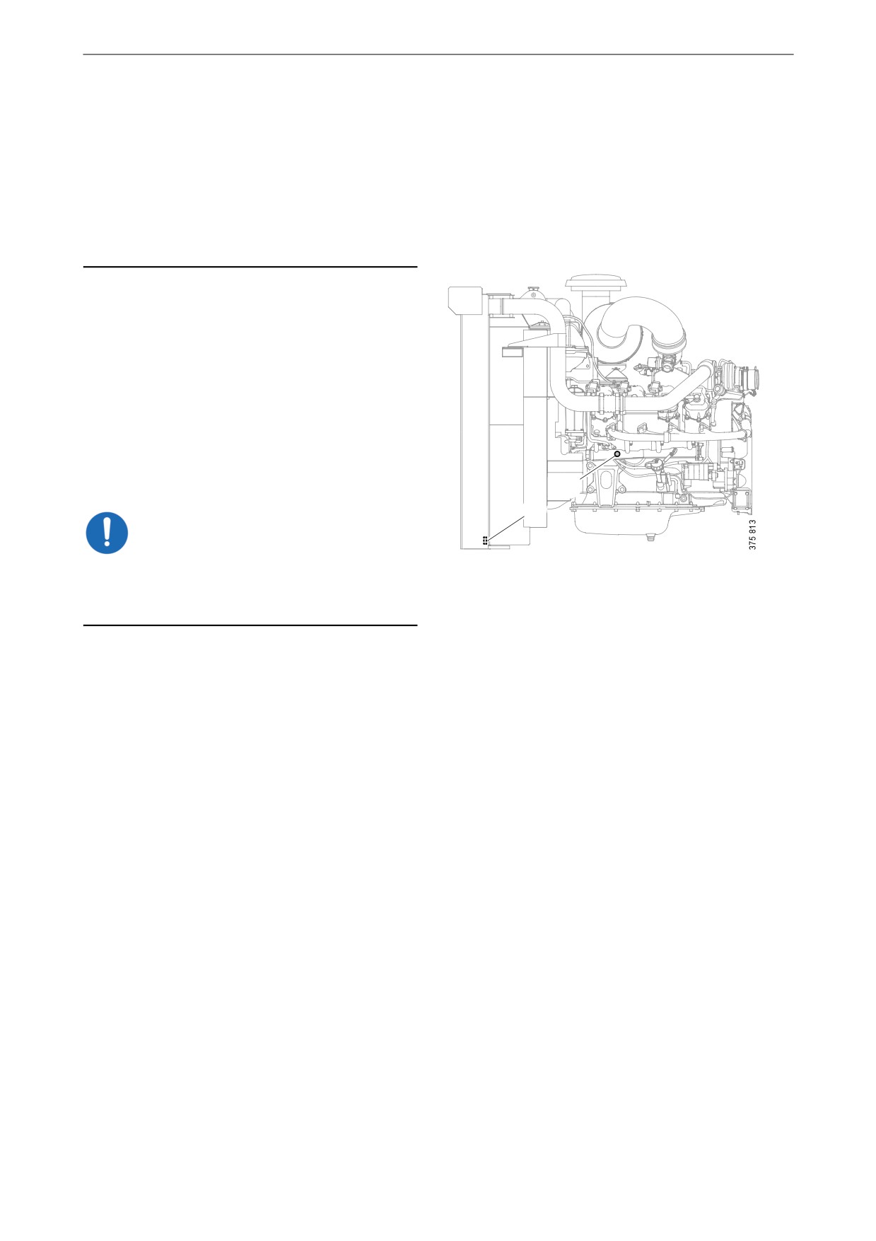
3. Connect the pump to the drain nipple in the
cylinder block (1).
4. Connect the pump's 2 cable terminals to the
battery's negative and positive terminal.
Make sure that the drainage starts. If the
drainage does not start: Change the position
of the cable terminals.
1
5. Repeat the procedure on the lowest draining
2
point of the cooling system (2).
39
Cooling system
Cleaning the cooling system
Internal cleaning: Removing oil and
grease in the cooling system
Note:
Clean the cooling system more often than speci-
Environment
fied in the maintenance interval if necessary.
Use a suitable container. Used coolant must be
disposed of as specified in national and interna-
External cleaning: Cleaning the radiator
tional laws and regulations.
and charge air cooler
IMPORTANT!
Always fit a new thermostat and a new cover to
the expansion tank after cleaning, as the oil in the
cooling system destroys the seals. If the engine is
Do not use caustic soda or other alkaline deter-
equipped with a coolant filter, also renew this fil-
gent as this could damage the aluminium.
ter.
Read the warning text on the detergent packag-
It may be necessary to wash it multiple times if
ing.
the cooling system is very dirty. One cause of
contamination can be that oil is lying on top of
1. Check that the radiator and the charge air
the coolant and collecting high up in the cooling
cooler are not clogged on the air side and that
system. If several rinses are needed, this is not
the cooling fins are not damaged.
necessarily because work has been carried out
incorrectly. Oil residues often need to be rinsed
2. Carefully scrape away any deposits from the
repeatedly from the expansion tank and the ex-
radiator cooling fins. Use a paraffin-based
ternal heating system to be completely clean.
engine cleaner if necessary.
3. Carefully straighten bent cooling fins using a
Repeated washing is more effective and prefera-
steel brush or the like.
ble to using higher concentrations of detergent
(max. 10%) or cleaning for a longer period (max
30 minutes).
If only a small amount of dirt has collected in the
expansion tank after cleaning, one extra rinse
and clean of the expansion tank only is usually
sufficient. There is no need to clean the whole
cooling system again.
1. Run the engine until it has reached operating
temperature and then drain the cooling sys-
tem following the previous description.
2. Remove the thermostat.
40
Cooling system
3. Fill the cooling system with clean, hot water
Internal cleaning: Removing deposits in
mixed with detergent 2 479 017. Detergent
the cooling system
2 479 017 must make up 5-10% (depending
on the degree of dirt) of the total coolant vol-
Environment
ume.
If detergent 2 479 017 is not available, use a
Use a suitable container. Used coolant must be
dishwasher detergent for household dish-
disposed of as specified in national and interna-
washers that does not foam. Concentration
tional laws and regulations.
1%.
4. Run the engine until it has reached operating
1. Run the engine until it has reached operating
temperature for approximately 20-30 min-
temperature and then drain the cooling sys-
utes. Remember to switch on the cab heating
tem following the previous description.
system, if one is installed.
2. Remove the thermostat.
5. Drain the cooling system.
3. Fill the cooling system with clean, hot water
6. Fill the cooling system with clean, hot water
mixed with radiator detergent which is based
and run the engine for about 20-30 minutes.
on sulphamic acid and contains dispersing
7. Repeat steps 3-6 if the cooling system is not
agents. Follow the manufacturer's instruc-
clean.
tions for the concentration and cleaning peri-
8. Drain the water from the cooling system.
od.
9. If necessary, clean the expansion tank by de-
4. Run the engine for the specified time. Re-
taching all hoses and rinsing and cleaning
member to switch on the cab heating system,
with a degreasing agent and a dishwashing
if one is installed.
brush.
5. Drain the cooling system.
Alternatively, dismantle the expansion tank
6. Fill the cooling system with clean, hot water
and clean it with water with 10% of detergent
and run the engine for about 20-30 minutes.
2 479 017. Fill the expansion tank with the
7. Drain the water from the cooling system.
mixture, shake it around and drain it. Renew
the cover of the expansion tank.
8. Reinstall the thermostat.
10. Fit a new thermostat.
9. Fill the cooling system with new coolant as
described in the next section.
11. Fill the cooling system with new coolant as
described in the next section.
External cleaning: Cleaning the radia-
12. Check again whether further dirt or oil has
tor and charge air cooler
collected in the expansion tank. Decide
1. Check that neither the radiator nor the charge
whether it it is necessary to carry out another
air cooler are clogged on the air side and that
full cleaning or whether only rinsing or
the cooling fins are not damaged.
cleaning of the expansion tank will suffice.
2. Carefully scrape away any deposits from the
radiator cooling fins. Use a paraffin-based
engine cleaner if necessary.
3. Carefully straighten bent cooling fins using a
steel brush or the like.
41

Cooling system
Filling coolant
This procedure applies when the cooling system
has been drained and needs to be filled with a
large amount of coolant.
Special tools
Number, designation
Illustration
2 443 679, coolant
pump
WARNING!
Use protective gloves as coolant can cause irrita-
tion if it comes in contact with the skin. Hot cool-
ant can also cause scalding.
IMPORTANT!
Mix the coolant as specified in the section head-
ed Coolant.
It is not permissible to top up large amounts of
coolant via the expansion tank. Filling via the ex-
pansion tank leads to air locks in the cooling sys-
tem which can lead to e.g. damage to the coolant
pump shaft seal.
42
Cooling system
Never fill a large amount of cold coolant in a hot
engine. There is great risk of cracks forming in
the cylinder block and cylinder heads.
Do not start the engine until the correct coolant
level has been obtained. If the engine is started
with an insufficient coolant level, it can damage
the coolant pump shaft seal, which leads to cool-
ant leakage.
1. Open the expansion tank cap.
2. Connect the coolant pump to the filler nipple
in the cylinder block (1).
3. Connect the pump's 2 cable terminals to the
battery's negative and positive terminal.
Make sure that the filling starts. If the filling
does not start: Change the position of the ca-
ble terminals.
4. Start the engine and run it at idling for
15 minutes.
1
2
IMPORTANT!
It is very important that the engine is idling. En-
gine overspeed could damage the coolant pump
shaft seal, which leads to coolant leakage.
5. Switch off the engine and fill with coolant to
the maximum level through the expansion
tank.
Air pockets may still be left in the cooling
system. These will disappear after the engine
has been operated for a period of time.
Therefore, the coolant may need topping up
at a later stage.
43

Fuel system
Fuel system
Cleaning the flame arrestor
and throttle at the flame lock
This procedure applies only if pure biogas is
used as a fuel.
IMPORTANT!
Read the safety precautions before starting work.
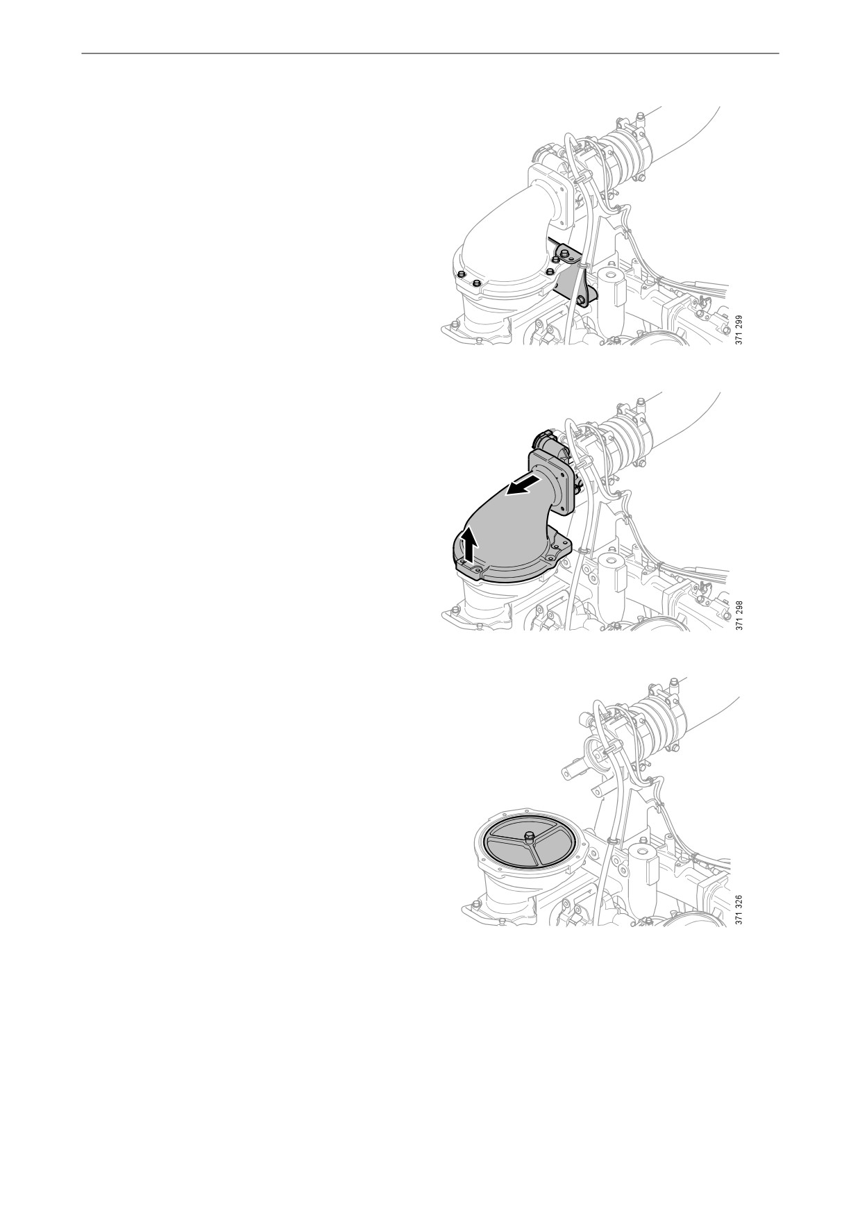
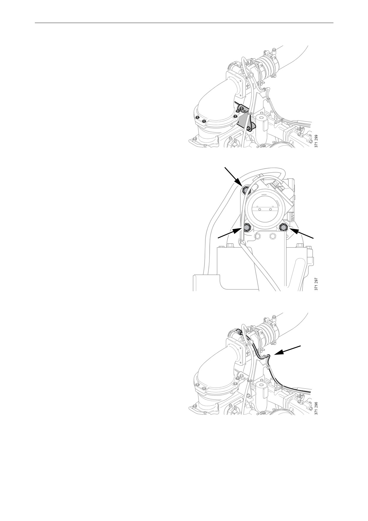
1. Detach the connector from the throttle.
2. Remove the screws securing the throttle
bracket to the flame arrestor.
44
Fuel system
3. Remove the flame arrestor housing bracket
and the screws.
4. Remove the upper part of the flame arrestor
housing and the throttle.
2
1
5. Remove the flame arrestor.
6. Clean the insert with degreasing agent. Re-
move dirt with a soft brush.
7. Rinse the insert with hot water.
8. Blow out any remaining water with com-
pressed air.
45

Fuel system
9. Remove the throttle.
10. Protect the throttle electrical connection
from moisture.
11. Clean the throttle with soap and water. Use a
soft brush to remove stubborn dirt.
IMPORTANT!
Only use soap and water. Solvents and degreas-
ing agents can damage the throttle.
12. Rinse the throttle with hot water.
13. Dry off the water.
14. Spray the outside of the throttle with water-
repellent anti-corrosive oil, for example
LPS1 or equivalent. Make sure that the oil
reaches the holes for the throttle shaft in the
throttle housing.
15. Renew the gasket.
16. Fit the throttle to the flame arrestor housing.
17. Check the O-rings. Renew them if necessary.
O-rings.
18. Fit the flame arrestor housing and the throt-
tle.
1
2
46
Fuel system
19. Fit the screws and the bracket.
20. Fit the screws securing the throttle bracket.
21. Fit the throttle connector.
22. Make sure the fuel system is not leaking. See
Leak testing after maintenance of the fuel
circuit.
47