Scania DC13 PDE. Industrial engine. Operator’s manual - part 4
Cooling system
Filling coolant
These procedures apply when the cooling system
has been drained and needs to be filled with a
large amount of coolant.
WARNING!
Use protective gloves as coolant can cause irrita-
tion if it comes in contact with the skin. Hot cool-
ant can also cause scalding.
IMPORTANT!
Mix the coolant as specified in the section head-
ed Coolant.
It is not permissible to top up large amounts of
coolant via the expansion tank. Filling via the ex-
pansion tank leads to air locks in the cooling sys-
tem which can lead to e.g. damage to the coolant
pump shaft seal. If a large amount of coolant
needs to be added, follow the instructions in the
section Filling coolant.
Never fill a large amount of cold coolant in a hot
engine. There is great risk of cracks forming in
the cylinder block and cylinder heads.
Do not start the engine until the correct coolant
level has been obtained. If the engine is started
with an insufficient coolant level, it can damage
the coolant pump shaft seal, which leads to cool-
ant leakage.
48

Cooling system
Filling coolant with coolant pump
Tool
Number, designation
Illustration
2 443 679, coolant
pump
1. Open the expansion tank cap.
2. Connect the coolant pump to the filler nipple
in the cylinder block. See illustration.
3. Connect the pump's 2 cable terminals to the
battery's negative and positive terminal.
Make sure that the filling starts. If the filling
does not start: Change the position of the ca-
ble terminals.
4. Start the engine and run it at idling for
15 minutes.
IMPORTANT!
It is very important that the engine is idling. En-
gine overspeed could damage the coolant pump
shaft seal, which leads to coolant leakage.
5. Switch off the engine and fill with coolant to
the maximum level through the expansion
tank.
Air pockets may still be left in the cooling sys-
tem. These will disappear after the engine has
been operated for a period of time. Therefore, the
coolant may need topping up at a later stage.
49

Cooling system
Refilling coolant with coolant trolley
Tool
Description
Illustration
Coolant trolley
1. Open the expansion tank cap.
2. Connect the coolant trolley to the filler nip-
ple in the cylinder block. See illustration.
3. Fill with coolant using coolant trolley to
pump up to the maximum level of the expan-
sion tank.
4. Disconnect the coolant trolley.
5. Start the engine and run it at idling for
15 minutes.
IMPORTANT!
It is very important that the engine is idling. En-
gine overspeed could damage the coolant pump
shaft seal, which leads to coolant leakage.
6. Switch off the engine and fill with coolant to
the maximum level through the expansion
tank.
Air pockets may still be left in the cooling sys-
tem. These will disappear after the engine has
been operated for a period of time. Therefore, the
coolant may need topping up at a later stage.
After filling, it may be good to start the engine
and check that no coolant leakage occurs.
50
Fuel system
Fuel system
Checking the fuel level
Check the fuel level and top up with fuel as nec-
Cleanliness requirements
essary.
Note:
IMPORTANT!
If the fuel tank has been run dry or if the engine
has not been used for a long time, bleed the fuel
The whole fuel system is very sensitive to dirt
system. See the section Bleeding the fuel system.
and even very small particles. Foreign particles
in the system can cause serious malfunctions. It
is therefore very important that everything is as
clean as possible when work is carried out on the
fuel system. Before repair work, the engine must
be washed. If possible, a hot water wash should
be used.
It is strictly forbidden to carry out any machining
work or work with compressed air near an open
fuel system.
Be extra careful and always use clean, lint-free
and dust-free clothes and disposable gloves
when working on the fuel system. Scania recom-
mends using Tegera 848 gloves.
Clean tools before they are used and do not use
any worn or chrome-plated tools. Material and
flakes of chrome may come off.
Clean connections and the surrounding area be-
fore removal. When cleaning, cloths or paper
which shed fibres must not be used. Use clean
and lint free cloths, part number 588 879.
Plug or cover the connections during removal.
Also clean the connections before the compo-
nents are fitted. Place removed components on a
thoroughly cleaned, dust-free surface. Scania
recommends using a stainless steel bench top,
part number 2 403 296. Cover the components
with a lint free cloth.
51
Fuel system
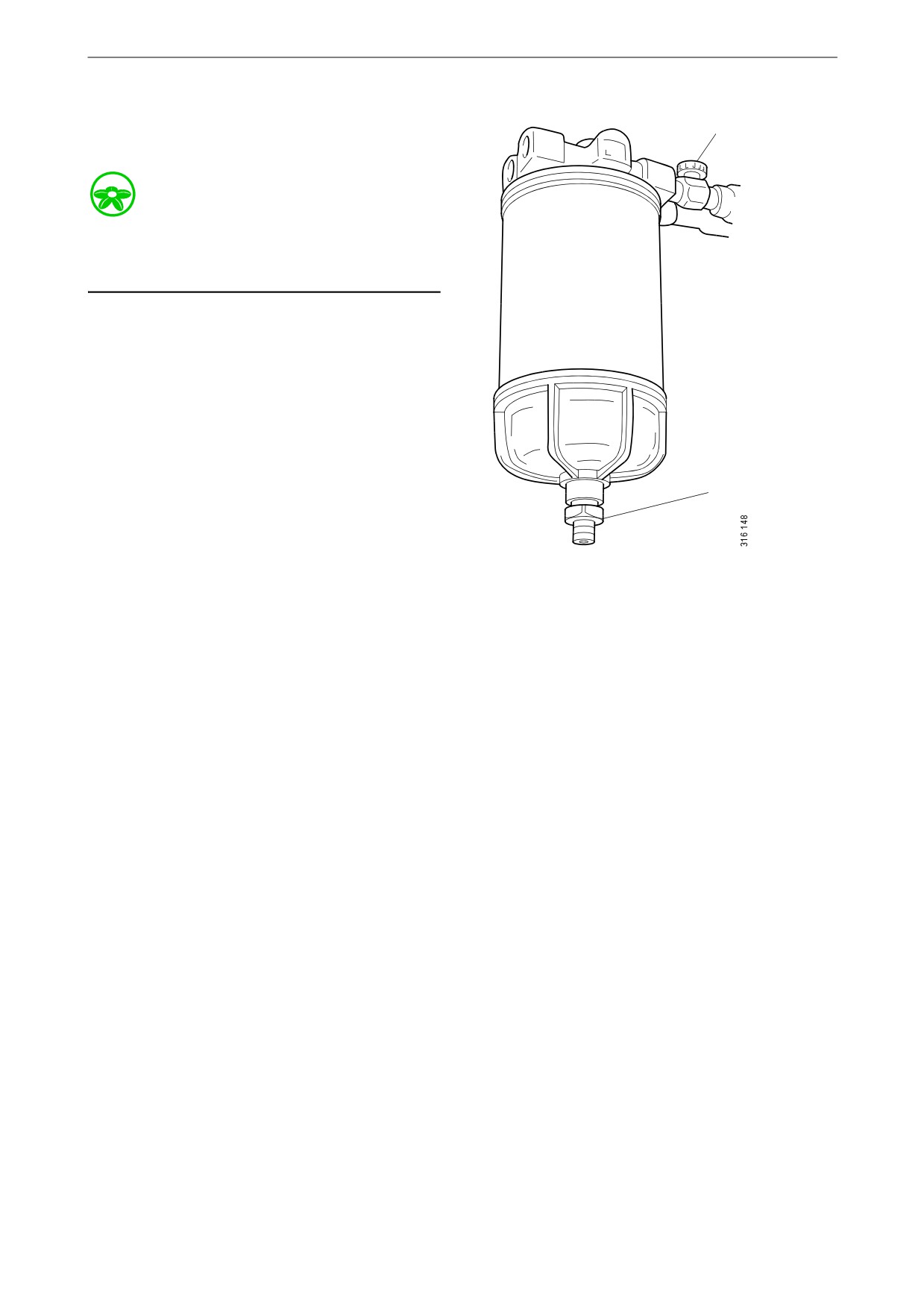
Renewing the water separat-
1
ing prefilter
Environment
Use a suitable container. The fuel collected must
be disposed of as specified in national and inter-
national laws and regulations.
Before starting work: Close the shut-off cock in
the fuel pipe, if there is one, and position a con-
tainer under the filter.
1. Open the drain tap on the filter cover and let
the fluid run down into the container.
2. Unscrew the filter cover.
3. Unscrew the filter from the filter head.
2
4. Discard the old filter and use a new filter.
5. Lubricate the O-ring in the filter cover with
engine oil.
6. Screw the filter cover onto the new filter by
1.
Shut-off cock.
hand. Make sure that the drain tap is fully
2.
Drain tap.
closed.
7. Lubricate the O-ring on the filter with engine
oil.
8. Fill the width of the filter with clean fuel.
9. Screw the filter into position until the O-ring
rests against the filter head. Tighten the filter
another 1/2 to 3/4 turn by hand.
10. Open the shut-off cock and check the system
for leaks.
11. Bleed the fuel system as per the following
section.
52
Fuel system
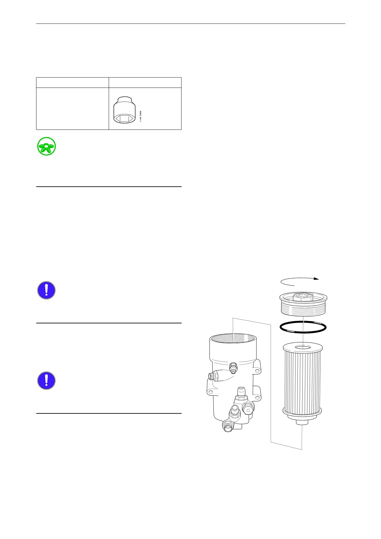
Renewing the fuel filter
Tool
Description
Illustration
Hexagon socket, 1/2",
36 mm
Environment
Use a suitable container. The fuel collected must
be disposed of as specified in national and inter-
national laws and regulations.
Before starting work: Close the shut-off cock in
the fuel pipe, if there is one, and position a con-
tainer under the filter.
1. Open the bleed nipple on the fuel filter hous-
ing to release any remaining pressure. It may
be difficult to unscrew the filter cover if the
system pressure has not fallen enough.
2. Unscrew the filter cover with the socket.
25 Nm
IMPORTANT!
Do not use an adjustable spanner or other open
tool as there is a risk of damaging the filter cover.
3. Lift the filter cover with filter element out of
the fuel filter housing. The fuel filter housing
will drain automatically (slowly) once the
filter element has been removed.
IMPORTANT!
If draining is not working, the remaining fuel
should be removed.
53

Fuel system
4. Unscrew the overflow valve and blow the
25 Nm
strainer in the filter housing clean. Also wipe
the bottom of the filter housing.
5. Undo the old filter element from the cover by
carefully bending it to one side.
6. Fit a new O-ring on the cover. Lubricate the
O-ring with O-ring grease.
7. Press a new filter element into the snap fas-
tener in the cover.
IMPORTANT!
Fit the filter element into the cover before plac-
ing it in the fuel filter housing or the filter ele-
ment might be damaged.
8. Press down the filter element into the hous-
ing with the cover. Screw on the filter cover
firmly with the socket. Tightening torque
25 Nm (18 lb-ft).
IMPORTANT!
Screw on the cover to the specified torque or the
filter element may break. Do not use an adjusta-
ble spanner or other open tool as there is a risk of
damaging the filter cover.
9. Bleed the fuel system as per the following
section.
10. Start the engine and check that no leakage
occurs.
54
Fuel system
Bleeding the fuel system
IMPORTANT!
The collected fuel must not be poured back into
the fuel tank.
Environment
Use a suitable container. The fuel collected must
be disposed of as specified in national and inter-
national laws and regulations.
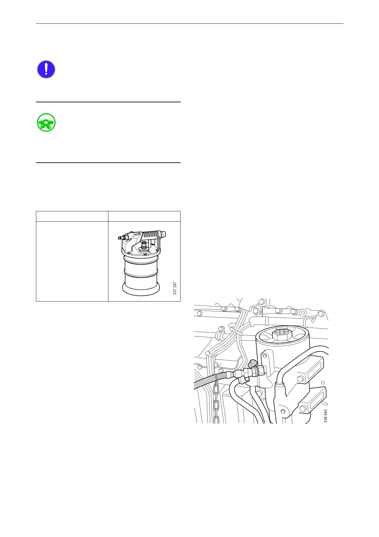
Bleeding the fuel system using a suc-
tion tool
Tool
Description
Illustration
Suction tool
1. Attach a clear plastic hose to the bleed nipple
on the fuel filter housing. Place the end of the
plastic hose in a container that holds at least
3 litres (1 US gallon).
55
Fuel system
2. Connect the suction tool.
3. Connect compressed air to the suction tool.
Turn the rotary control to create a vacuum.
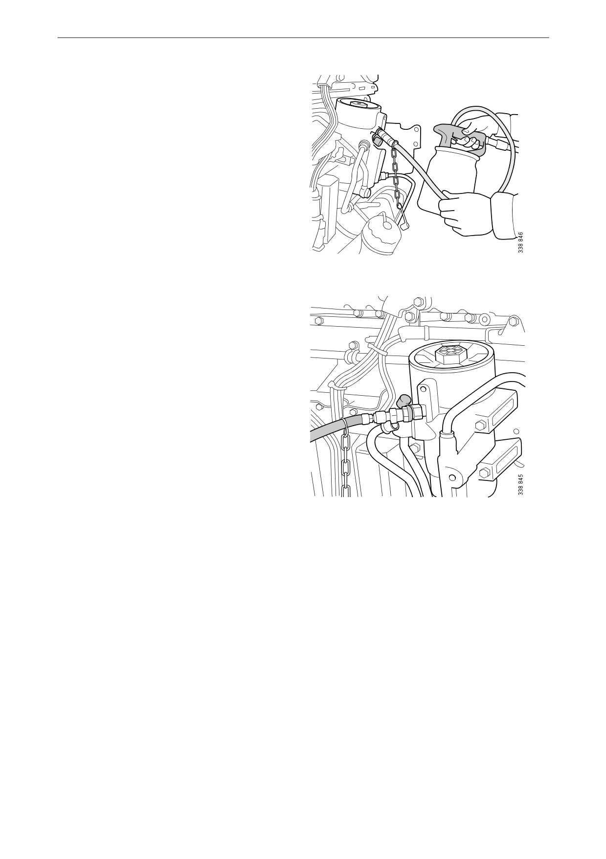
4. Open the bleed nipple. Hold the suction tool
straight and draw out at least a full container
of fuel.
Once the fuel coming out of the hose is free
of air bubbles, then bleeding is complete.
5. Close the bleed nipple. Remove the hose and
suction tool.
6. Start the engine and check that no leakage
occurs.
56

Fuel system
Bleeding the fuel system using a
hand pump
1. Attach a clear plastic hose to the bleed nipple
on the fuel filter housing (1). Place the end of
the plastic hose in a container that holds at
2
least 3 litres (1 US gallon).
2. Open the bleed nipple and pump with the
hand pump (3) until fuel comes out of the
hose. If the fuel system is empty, it is neces-
sary to pump approximately 100 strokes in
order to draw up the fuel. Depending on the
1
installation, a significantly greater number of
pump strokes may be required before fuel
comes out.
3. Pump until fuel without air bubbles comes
out, approximately 20 strokes.
3
4. Close the bleed nipple and remove the hose.
5. Transfer the hose to the fuel manifold bleed
nipple (2).
6. Open the bleed nipple and pump using the
1. Fuel filter housing bleed nipple.
hand pump (3) until fuel without air bubbles
2. Fuel manifold bleed nipple.
appears, approximately 50 pump strokes.
3. Hand pump.
7. Close the bleed nipple and remove the hose.
8. Pump approximately 20 strokes with the
hand pump until the overflow valve opens. A
hissing sound should be heard.
9. Start the engine. The engine should be easy
to start.
10. If the fuel filter has been renewed, check that
no fuel is leaking from the filter. If there is
leakage, tighten the filter more.
57

Other
Other
2
5
4
Checking the drive belt
IMPORTANT!
Before starting, make a note of how the drive belt
is fitted. Refit the drive belt with the same direc-
3
tion of rotation as it had before removal.
2
1. Check the drive belt for cracks. Renew the
drive belt if deep cracks have formed.
1
Note:
Example of a drive belt.
Small and shallow cracks are normal and form
1. Crankshaft.
after only a few hours of operation. They do not
2. Idler roller.
mean that the drive belt needs to be renewed. If
there are many deep cracks, or if parts of the
3. Alternator.
drive belt have started to come off, the drive belt
4. Belt tensioner.
must then be renewed.
5. Coolant pump.
Example of a minor crack in the drive belt. The drive
The drive belt has deep cracks and must be renewed.
belt can be refitted.
58
Other
2. Check drive belt wear. Renew the drive belt
if it is too worn.
The drive belt is starting to become worn, but can be
The belt is worn down to the cord. The drive belt
refitted.
must be renewed.
Checking for leaks
IMPORTANT!
If serious leakage occurs, contact your nearest
workshop.
1. Start the engine.
2. Check for oil, coolant, fuel, air or exhaust
leaks.
3. Tighten or renew leaking connections.
Check the overflow holes which show
whether the O-rings between the cylinder
liners and crankcase are leaking.
4. Check whether the drain hole on the coolant
pump is blocked. If there is a leak, renew the
seal in the pump or the complete coolant
pump.
59
Other
Checking and adjusting the
valve clearance and unit in-
jectors
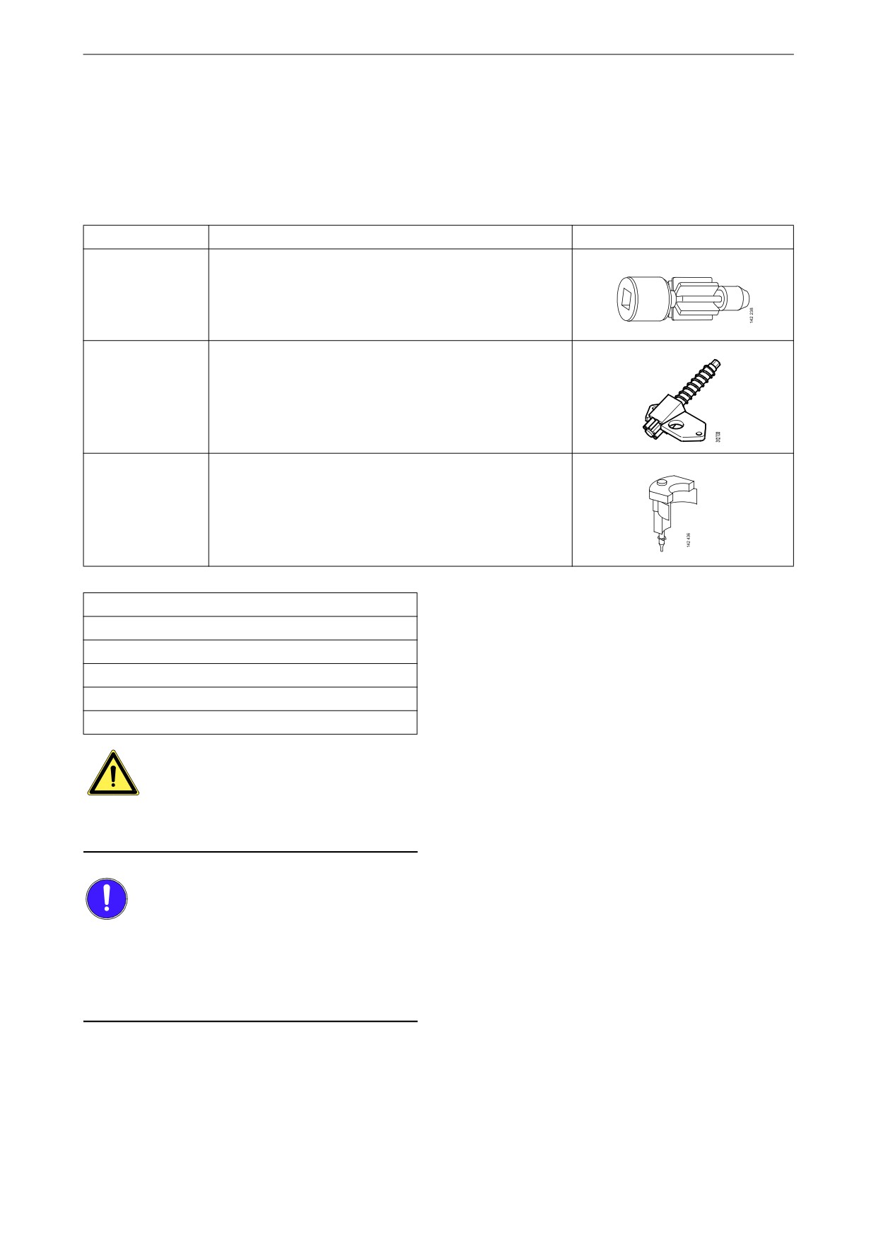
Special tools
Number
Description
Illustration
99 309
Turning tool for rotating the flywheel from below
2 402 509
Turning tool for rotating the flywheel from above
99 442
Setting tool
Other tools
Torque wrench, 0-50 Nm
Waterproof felt-tip pen
Feeler gauge 0.45 and 0.70 mm
Flash light
Mirror
WARNING!
Block the starting device. If the engine starts un-
expectedly, there is a serious risk of injury.
IMPORTANT!
The engine must be cold when the work is car-
ried out.
Remember to remove the turning tool from the
flywheel after adjustment.
Note:
Carry out the working without pausing, so that
no step is overlooked.
60
Other
Carry out a check and adjustment of the valve
clearances and the unit injectors one more time
after the first 500 hours of operation. After this,
adjustment according to the regular interval
takes place, which is every 2,000 operational
hours.
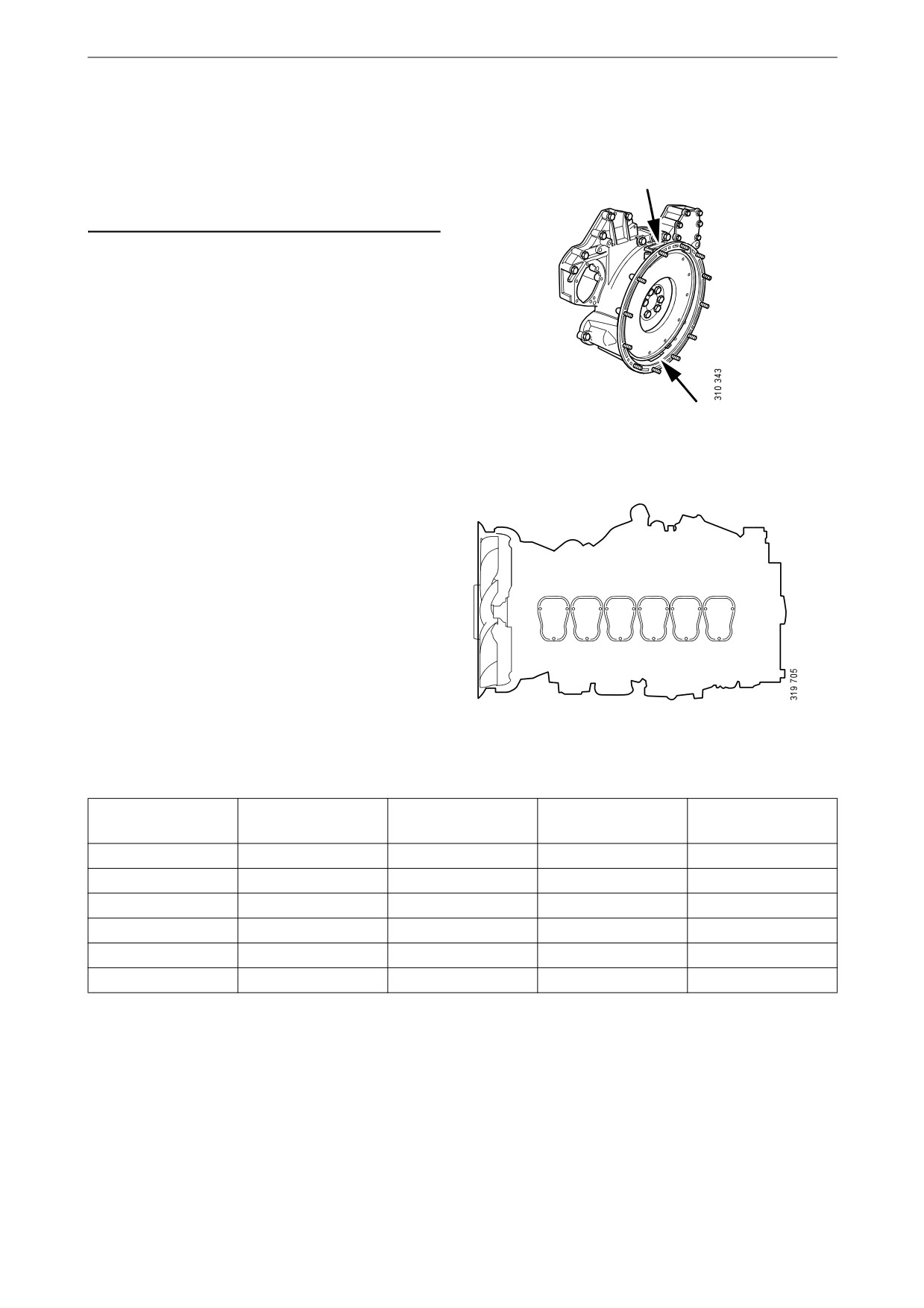
On the flywheel is engraved the reference infor-
mation UP TDC, DOWN TDC and the angle in-
dications listed in the table below. Depending on
the engine installation, this information is visible
in one of the windows, either furthest up or fur-
thest down on the flywheel. See illustration.
Upper and lower window to read the engraving on
the flywheel.
Workflow table
Adjust valves and injectors according to the table
below. Follow the respective column depending
on whether you are reading the engraving on the
1
2
3
4
5
6
flywheel in the lower or the upper window. Start
adjustment at the top of the table.
Order of cylinders.
Reading in the low-
Valve transition on
Adjust valves on
Adjust injector on
Reading in the up-
er window
cylinder
cylinder
cylinder
per window
DOWN TDC
1
6
2
UP TDC
120/480
5
2
4
300/660
240/600
3
4
1
60/420
DOWN TDC
6
1
5
UP TDC
120/480
2
5
3
300/660
240/600
4
3
6
60/420
61
Other
Checking and adjusting the valve
clearance
Valve clearance, specifications
Intake valve
0.45 mm (0.018 in)
Exhaust valve
0.70 mm (0.028 in)
Tightening torque
Lock nut for valves
35 Nm (26 lb/ft)
1. Clean the rocker covers and the area around
them.
2. Remove the rocker covers.
3. Use the turning tool appropriate to the instal-
lation of the engine. Tool 99 309 is used to
rotate the flywheel from the underside of the
engine and tool 2 402 509 is used from the
top side.
4. Start adjusting one cylinder according to the
table. Rotate the flywheel until the correct
engraving can be read on the flywheel. It
may be necessary to rotate it more than 1 rev-
olution.
Rotate the flywheel in the rotational direc-
tion of the engine, which is clockwise
viewed from the front of the engine and anti-
clockwise viewed from the back of the en-
gine.
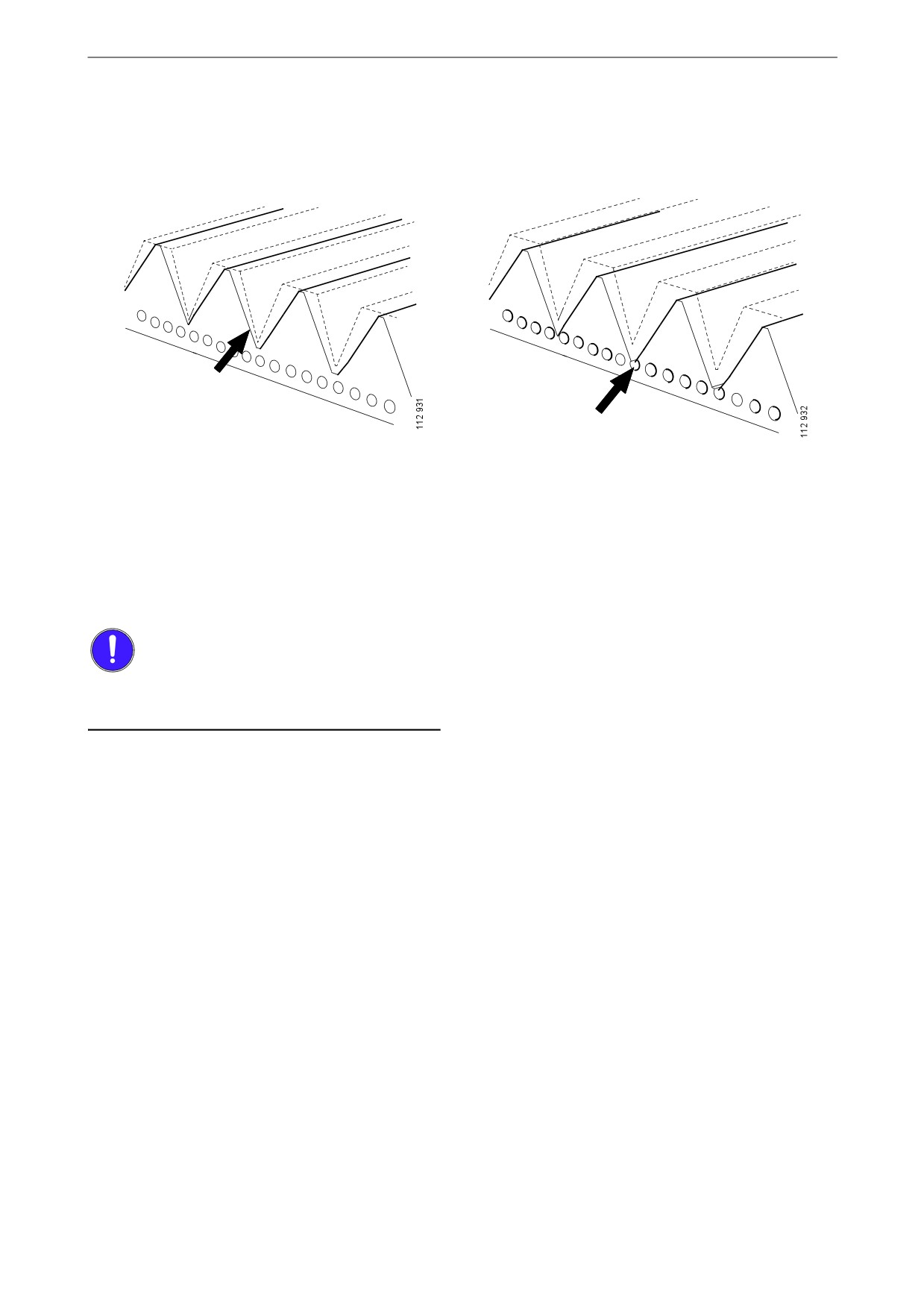
During a valve transition, the exhaust valve
(the long arm) is closing at the same time as
the intake valve is opening.
The UP TDC engraving on the flywheel is
now visible in the window furthest up on the
flywheel. The DOWN TDC engraving is vis-
ible in the lower window.
5. Read Workflow table on the previous page to
3
see which valve to adjust.
6. Stick the feeler gauge under the pressure pad
of the rocker arm and check the valve clear-
4
ance.
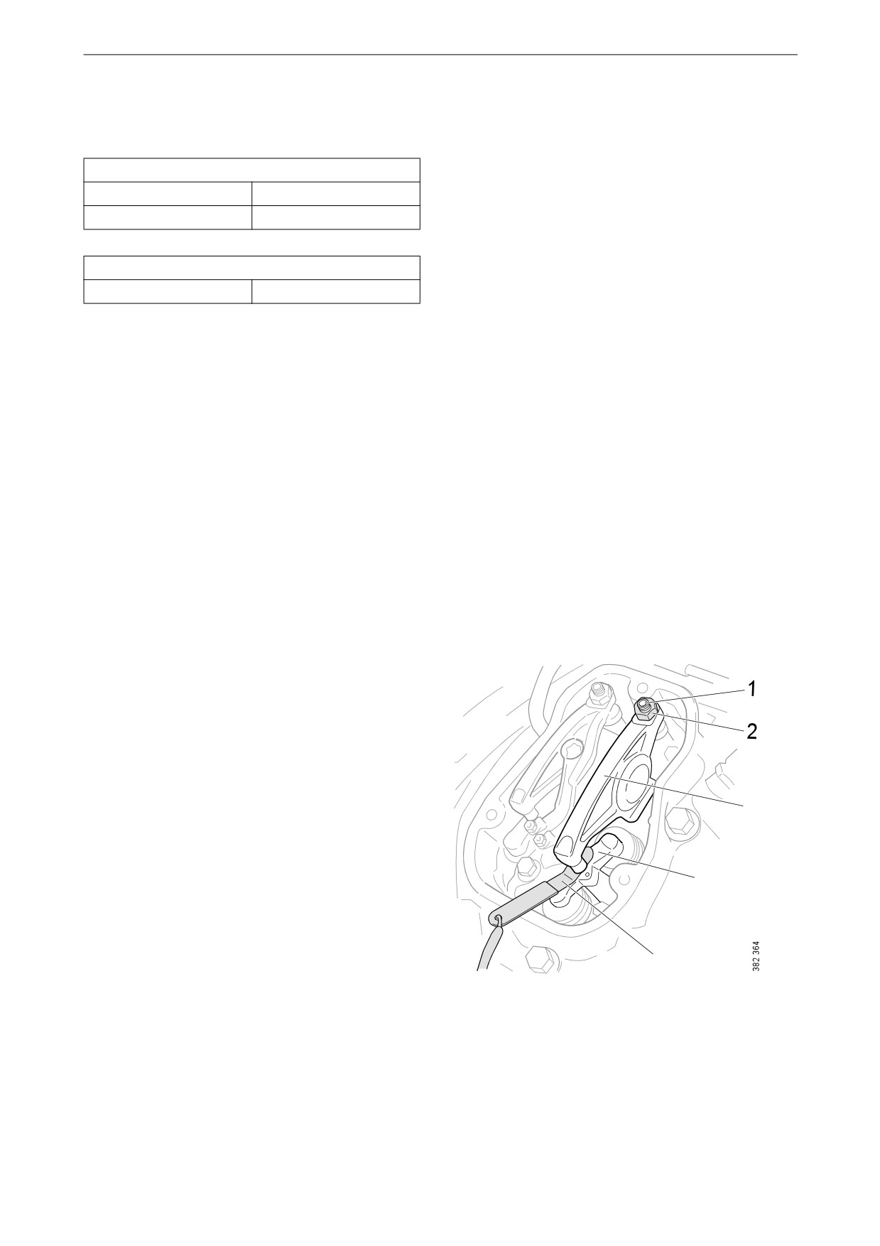
7. If necessary, adjust the valve clearance by
a) loosening the lock nut on the end of the
rocker arm
5
b) adjusting the valve clearance with the ad-
justing screw
1.
Adjusting screw.
c) tightening the lock nut.
2.
Lock nut.
8. Mark the rocker arm with the felt-tip pen and
3.
Rocker arm.
adjust the unit injector according to the next
4.
Valve bridge.
section. Then continue on to the next cylin-
5.
Feeler gauge.
der according to the table.
62
Other
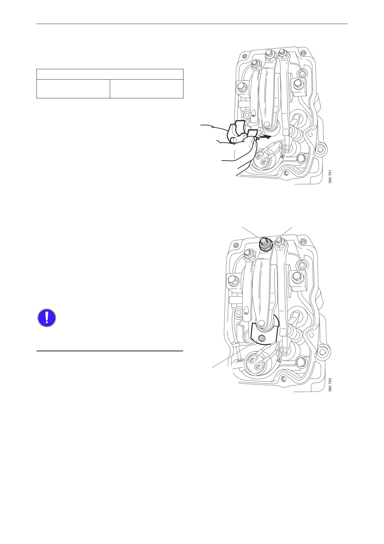
Checking and adjusting the unit in-
jectors
Tightening torque
Lock nut for unit injec-
39 Nm (29 lb/ft)
tors
1. See the Workflow table for details of the in-
jectors to be adjusted.
2. Fit the setting tool with the metal plate
around the unit injector.
The unit injector is correctly set when the
3
2
small piston (1) is level with the flat upper
surface of the tool. Use a finger to check.
You can feel very small differences. See also
the illustrations on the next page.
3. If necessary, adjust the unit injector by
a) loosening the lock nut (2)
b) adjusting the unit injector using the adjust-
ing screw (3)
c) tightening the lock nut.
IMPORTANT!
Remove the setting tool when the adjustment is
done.
4. Mark the injector with the felt-tip pen and
1
continue adjustment according to the table.
63