Scania Generator set en-GB 2 374 139. Operator’s manual - part 1
Operator's manual
Scania
Generator set
en-GB 2 374 139
Issue 2.0
Introduction
3
Function
3
Variants
3
Personnel
4
Installation inspection
4
Operator’s manuals
4
Plates
5
Safety
6
Different types of advisory
6
Safety precautions
7
Transport and installation
9
Dimensions
9
Weights
9
Actions prior to transport
10
Lifting the generator set
11
Load securing the generator set
13
Installing the generator set
14
Actions prior to starting after transport
27
Generator set design
28
Base frame
28
Canopy
29
Engine/generator set
30
Fuel system
31
Cooling system
32
Intake and exhaust system
33
Battery system 24 V
34
Central electric unit for current consumers. .
39
Operation
40
Instrument panel
40
Operating modes
41
Application modes
41
Operation
42
Before operation
42
Operation
42
Refuelling
42
Maintenance
44
Generator sets with few hours of operation
45
Maintenance intervals for generator set
46
Batteries
47
Exhaust system
50
Engine
50
Generator
51
2
Introduction
Introduction
This Operator’s manual describes the operation
of Scania generator sets. The information in this
manual was correct at the time of going to press.
Scania reserves the right to make alterations
without prior notice.
Note:
Always use Scania spare parts for repair work.
Function
The generator set can act as the primary power
source in an electrical consumer network or as a
stand-by generator set that is activated when the
main electric power network fails.
The generator set can operate independently or
be connected together with other generator sets
for parallel operation.
The generator sets can supply output power of
250-600 kVA (50-60 Hz).
Variants
This Operator’s manual does not describe each
specific generator set. Scania generator sets are
available in a large number of variants:
• With or without canopy.
• CE marked or not CE marked.
• Multiple options for engine and generator, the
choice depends on the power needed.
• Several options of instrument panels, the
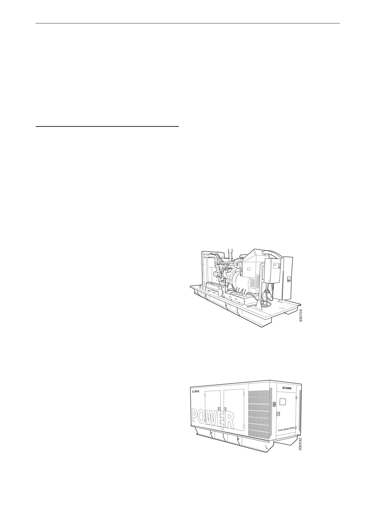
Open generator set
choice depends on the generator set operation
type.
• With or without a number of options.
This Operator's manual gives an overview of a
generator set which is either open or equipped
with a canopy.
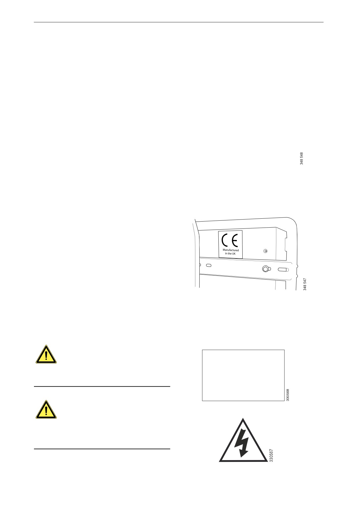
Scania Genset SG500
Generator set with canopy
3
Introduction
Personnel
REQUIREMENT!
Installation, commissioning, operation, mainte-
nance and repairs must be carried out by trained
and qualified staff who are authorised to perform
the work.
Installation inspection
When the generator set has been commissioned,
an installation inspection must be performed by
Scania or an inspection company appointed by
Scania. An inspection record must be completed
and sent to Scania.
REQUIREMENT!
Scania must approve the installation before the
generator set may be commissioned.
Operator’s manuals
The engine and instrument panel are described in
separate instruction manuals. A complete Opera-
tor’s manual for the generator set comprises the
following instruction manuals:
• Generator set (this Operator’s manual)
• Industrial engine
• Instrument panel
4
Introduction
Plates
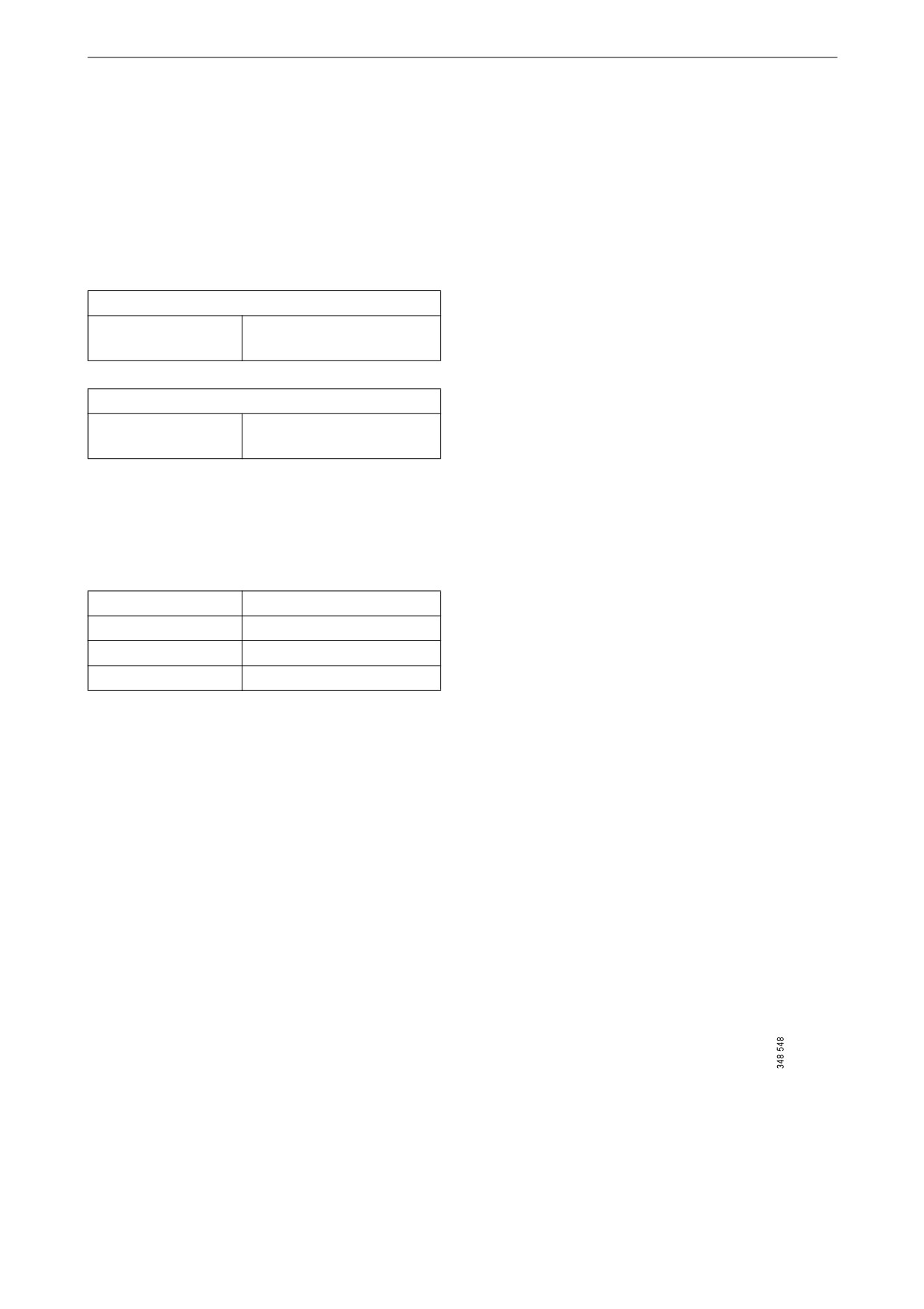
AC Generating Set
Every generator set has a plate which indicates
Manufac tur ed under lic enc e in the UK b y A J Power Limit ed
the generator set's rated voltage, rated power and
ID M40041A/001
FA3-AJ360P-5S1
rated current, among other things. The plate is lo-
Serial Number
Same as engine
cated on the generator terminal box.
Model
SG360PA5-01
The generator set serial number is the same as the
Phases
3
engine serial number. This is indicated on the en-
Rated Frequency (Hz)
50
gine data plate. See the Industrial engine Opera-
Rated Voltage (V)
400/230
Rated Power (kVA)
330.0
tor’s manual.
Rated Power (kW)
264.0
The serial number is very important when con-
Rated Power Factor (pu)
0.8
Rated Current (A)
476.3
tacting Scania for technical support or when or-
Rated Speed (rpm)
1500
dering spare parts.
Altitude (met ers)
152.4
Ambient Temp (deg C )
25
Mass (kg)
4000
Example of plate
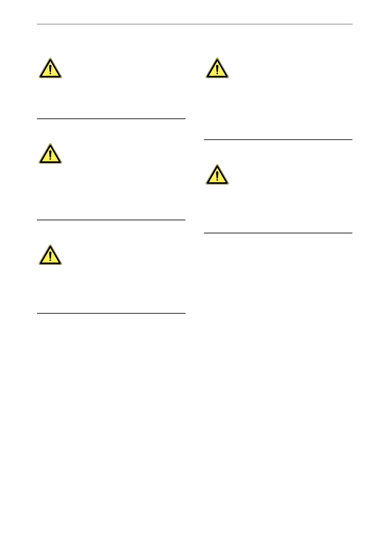
On CE marked generator sets, the CE marking is
located at the rear of the central electric unit.
CE marking
Warning stickers
The generator set is supplied with general warn-
ing stickers. The warning stickers must be re-
placed if they come off or have become illegible.
WARNING!
DANGER
The generator set can be remotely controlled and
THIS MACHINE IS
may start without warning.
REMOTELY CONTROLLED
AND MAY START
WITHOUT WARNING
WARNING!
A warning sticker with a lightning symbol indi-
cates that there is a voltage within the casing that
is dangerous for a person.
5
Safety
Note:
Safety
Advisories preceded by Note: refer to informa-
Different types of advisory
tion important to ensure the best possible opera-
tion and functionality. Example:
Warning!
Note:
All advisories preceded by the word Warning are
Select a generator set with a canopy if it is to be
very important. They warn of serious faults and
located outdoors.
incorrect operation that could lead to personal in-
jury. Example:
WARNING!
Environment
The generator set must be installed and commis-
sioned in full agreement with current national,
This Operator’s manual contains specially high-
local or regional regulations, standards or other
lighted text with instructions to help protect the
requirements.
environment during maintenance. Example:
Environment
Used batteries must be disposed of as specified
Important!
in national and international law.
Advisories preceded by the word Important warn
of faults and incorrect operation that could lead
to equipment being damaged. Example:
IMPORTANT!
An open generator set must be transported and
stored under cover.
6
Safety
Safety precautions
WARNING!
Read and understand all safety precautions and
warnings before installation, commissioning,
The generator set can be remote-controlled and
operation and maintenance actions of the gener-
start without prior warning. Therefore, set the
ator set.
battery master switch (option) to the OFF posi-
tion or disconnect the battery negative cable be-
Only start the generator set if it can be done safe-
fore any work is carried out on the generator set.
ly. Never run a generator set with known faults.
Electrical installation
WARNING!
WARNING!
Electrical cables and components in the genera-
The generator set must be installed and commis-
tor set may be live with lethal voltage.
sioned in full agreement with current national,
local or regional regulations, standards or other
When any hatch is opened while working on the
requirements.
generator set, its electrical cables and compo-
nents are unprotected.
Work may only be carried out by trained and
qualified personnel.
WARNING!
Only trained and qualified personnel authorised
Electric shock
to carry out this work can install, commission
and perform maintenance on the generator set.
WARNING!
Always cut off the power and take a reading be-
WARNING!
tween a conductor and ground before starting
work on the generator set. This is to ensure no
When a generator set with a canopy is in opera-
voltage remains in the system. High voltage may
tion, all hatches must be closed. The hatches may
cause damage, injury or even death.
only be opened once the generator set has been
switched off and when required by the work.
7
Safety
24 V and 230 V central electric unit
Noise
WARNING!
WARNING!
Cut the 230 V voltage before opening the central
Always wear ear defenders in the vicinity of a
electric unit front hatch to reset tripped miniature
generator set in operation. Long-term exposure
circuit breakers. Otherwise there is a risk of seri-
to noise levels above 85 dBA is harmful to hear-
ous personal injury.
ing.
A generator set without a canopy can cause noise
levels of above 105 dBA.
Hot surfaces
WARNING!
Batteries
The exhaust manifold, turbocharger, cooling
WARNING!
package and generator can become extremely
hot during operation. Do not touch these compo-
Batteries contain and emit oxyhydrogen gas, par-
nents when the generator set is in operation, and
ticularly during charging, and this gas is flamma-
make sure that they have cooled down sufficient-
ble and highly explosive. There must be no
ly before any maintenance is carried out.
smoking, naked flames or sparks near the batter-
ies or the battery compartment.
Moving parts
WARNING!
A generator set contains many mechanical mov-
ing parts. Remove protection devices and belt
guards with caution and only if it is absolutely
necessary to do so. Do not run a generator set
without all protection devices in place.
8
Transport and installation
Transport and installation
Dimensions
Generator set with canopy
There are two alternative sets of dimensions for
a generator set with canopy, these are as follows:
Alternative A
Length x width x
5,400 x 1,750 x 1,750 mm
height
Alternative B
Length x width x
5,000 x 1,600 x 1,750 mm
height
Open generator set
An open generator set has the following dimen-
sions:
Length x width
3,600 x 1,100 mm
Height DC09
approx. 1,835 mm
Height DC13
approx. 2,140 mm
Height DC16
approx. 2,245 mm
Weights
AC Generating Set
The weight of the generator set is indicated on
Manufac tur ed under lic enc e in the UK b y A J Power Limit ed
the plate located on the generator terminal box.
ID M40041A/001
FA3-AJ360P-5S1
Serial Number
Same as engine
Model
SG360PA5-01
Phases
3
Rated Frequenc y (Hz)
50
Rated Voltage (V)
400/230
Rated Power (kVA)
330.0
Rated Power (kW)
264.0
Rated Power Factor (pu)
0.8
Rated Current (A)
476.3
Rat
ed Speed (rpm)
1500
Altitude (met ers)
152.4
Ambient Temp (deg C )
25
Mass (kg)
4000
Example of plate
9
Transport and installation
Actions prior to transport
1. Check that the central electric unit circuit
breaker is in the 0 position and that any bat-
tery master switch (option) is in the off posi-
tion.
2. Check that no cables are connected to the
generator set.
3. Drain the fuel tank (applies to certain types
of transport).
4. Remove the batteries (applies to certain
types of transport).
5. Check that there is no loose equipment on the
generator set.
6. Close and lock all hatches.
7. Take appropriate action to protect the gener-
ator set against external damage.
IMPORTANT!
An open generator set must be transported and
stored under cover.
10
Transport and installation
Lifting the generator set
The generator set can be lifted in various ways
depending on its equipment:
• Lifting using slings connected to the four load
securing eyes in the base frame.
• Lift using straps connected to lifting eyes on
the roof that are part of a built-in lifting de-
vice. This is an option and only applies to
generator sets with canopy.
• Lifting using a lift fork in the pre-drilled holes
(option).
WARNING!
Lifting devices must be approved for the weight
of the generator set. The weight is indicated on
the plate located on the generator terminal box.
WARNING!
Do not work or stand under a suspended load.
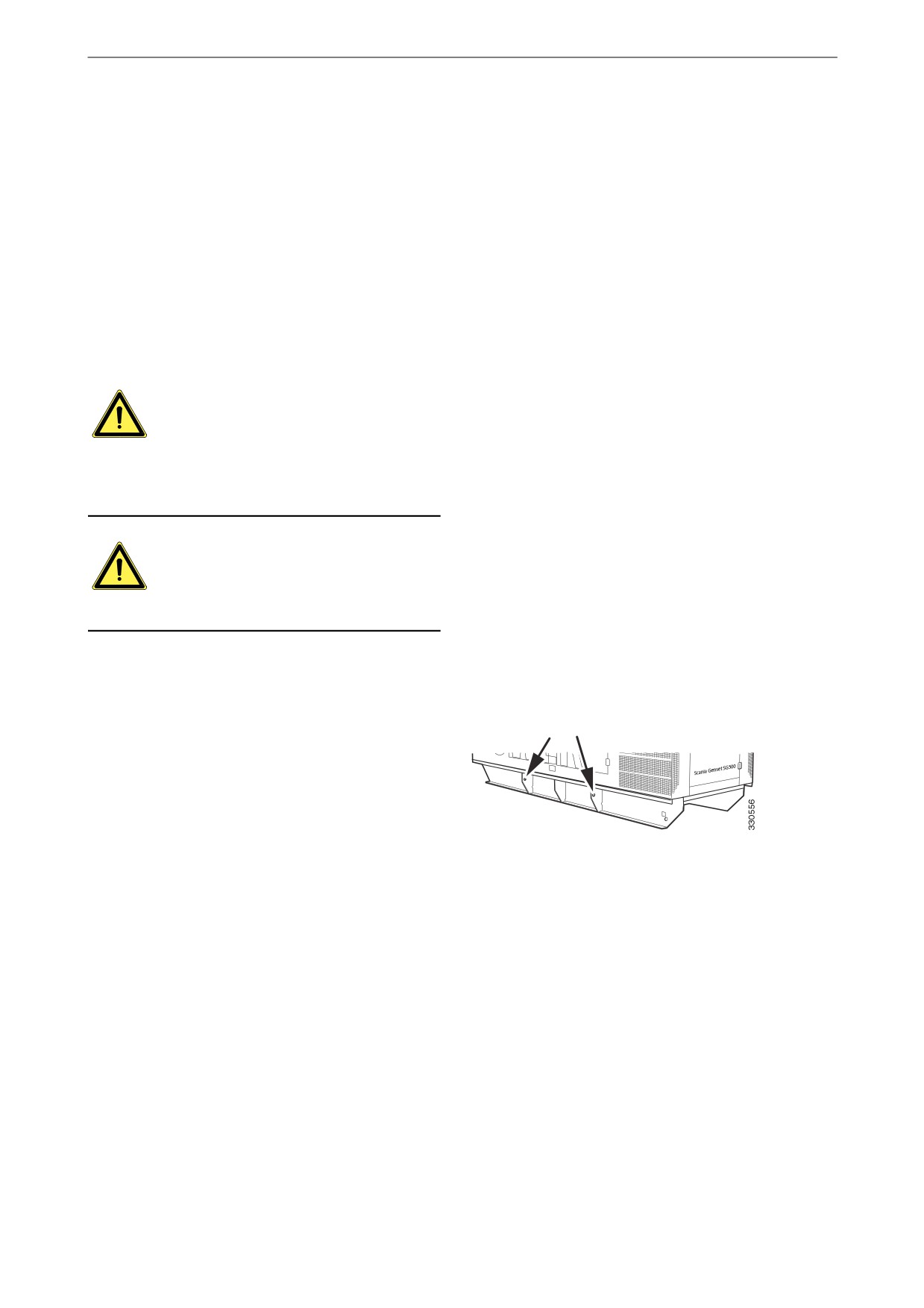
Lifting in load securing eyes
The generator set has four load securing eyes lo-
cated on the two longitudinal frame members of
the base frame.
Lift the generator set by connecting thongs to the
four eyes.
Load securing eyes on one frame member
11
Transport and installation
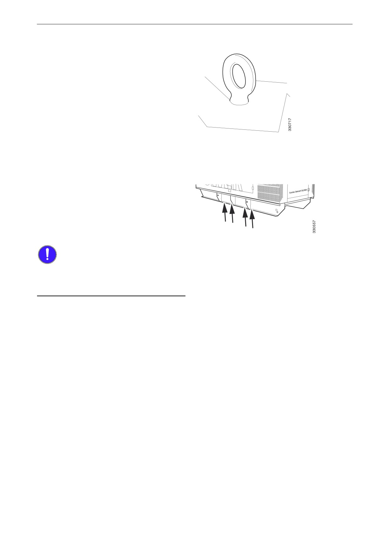
Lifting using the built-in lifting device
(option)
A generator set with a canopy equipped with a
built-in lifting device has a lifting eye on the
roof.
Lift the generator set by connecting a thong to
the lifting eye.
Lifting eye
Lifting using a lift fork in the pre-
drilled holes (option)
Lift fork brackets can be screwed into place in
pre-drilled holes in the two longitudinal mem-
bers of the base frame.
Lift fork brackets are screwed into these holes
IMPORTANT!
Lift fork brackets must be removed when trans-
porting a generator set with a canopy in a stand-
ard ISO container.
12
Transport and installation
Load securing the generator
set
Safety precautions
WARNING!
Use gloves when handling load securing equip-
ment.
Loading onto a load carrier
Loading onto a load carrier is described in the
documentation of the loader/load carrier.
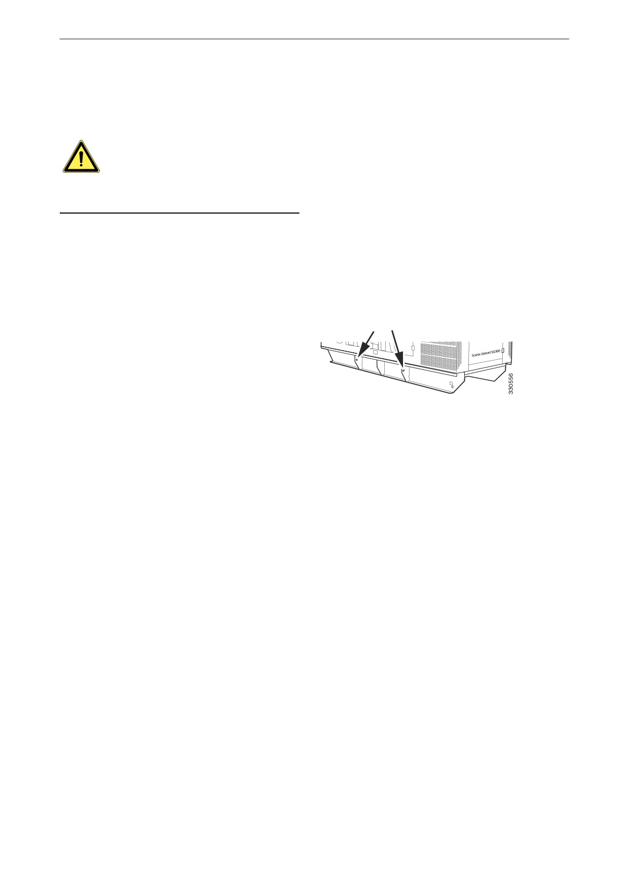
Load securing
Secure the generator set in the four load securing
eyes located on the two longitudinal frame mem-
bers of the base frame.
Load securing eyes on one frame member
13
Transport and installation
Installing the generator set
Selecting a site for installation
Selecting an installation site for the generator set
is an important part of installation. The following
section details the general factors that impact the
installation site. The particular factors that im-
pact installation outdoors and indoors are de-
tailed overleaf.
•
It must be possible to install a ground elec-
trode. During operation the generator set
must be connected to an ground electrode that
complies with applicable regulations. If there
is no ground electrode there is a risk of per-
sonal injury due to electrical shock.
•
The safe routing of cables underground must
be possible. Cables that have been laid out
must be protected.
•
There must be access to a permanent 230 V
electrical power system or other power sup-
ply for a built-in battery charger (option) or
engine heater (option).
•
Take preventive action to minimise the risk of
fire. Be aware of the fire risks caused by hot
exhaust pipes, exhaust hoses or exhaust gases
coming into contact with flammable material.
•
The location of the generator set adjacent to
solid surfaces, such as concrete walls, can af-
fect the noise level of the generator set
through echoing. If avoiding noise is particu-
larly important: Contact Scania for advice.
•
There must be enough space around the gen-
erator set to allow maintenance and repair.
•
The maximum inclination of the generator set
during operation depends on the type of oil
sump in the engine, see the Operator's manual
Industrial engines.
•
Access to the generator set must be restricted
for unauthorised personnel.
•
Where installation is permanent Scania rec-
ommends that the generator set be secured to
the floor.
14
Transport and installation
Installing outdoors
Note:
Select a generator set with a canopy if it is to be
located outdoors.
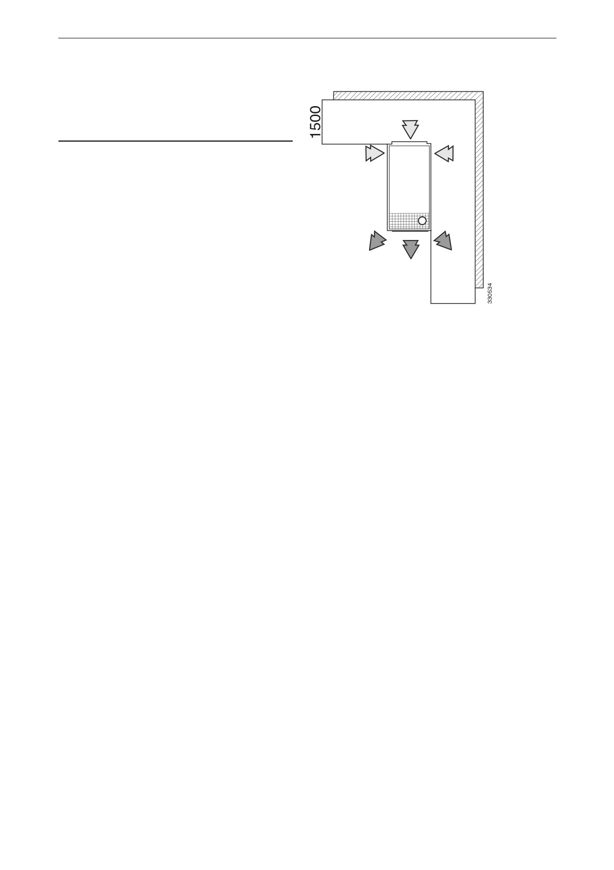
• There must be an adequate air flow for air in-
takes and air vents. This is vital to the opera-
tion of the generator set. As a guideline value
when installing a generator set with a canopy
outdoors, leave a space of at least 1,500 mm
all around.
• The installation site must be protected from
exposure to airborne contaminants such as
aggressive or conductive particles, oil mist,
fumes, engine exhaust gases or other contam-
inants.
1500
• Select an installation site where contaminants
Space around the generator set
in the form of sand, dust and other contami-
nants are to the greatest possible extent pre-
vented from entering the air intake and from
blocking the air vent.
• If possible, avoid setting the generator up
without protection from solar radiation.
• Locate the generator set so as to protect it
from surface water in the event of rain.
Installing indoors
• There must be adequate ventilation for intake
air and exhaust air.
• It must be possible to lead exhaust gases and
cooling air to the outside of the building with-
out any leaking back into it.
• If possible, place extra fuel tanks outdoors.
15