Scania DC09 PDE. Industrial engine. Operator’s manual - part 2
Starting and running
Depending on the engine configuration, the fol-
The incorrect oil pressure alarm has the follow-
lowing alarm functions may also be available:
ing functions:
• Alarm only.
• Alarm only.
• Alarm and engine shutdown at the highest
• Alarm and torque reduction by 30%.
limit value.
• Alarm and engine shutdown.
• Alarm, torque reduction at the lowest limit
• Alarm and engine shutdown override control.
value and engine shutdown at the highest lim-
it value.
Note:
• Alarm and engine shutdown at the highest
High oil pressure (above 6 bar/87 psi) is normal
limit value with the possibility of engine shut-
if the engine is cold when started.
down override control.
• Alarm, torque reduction at the lowest limit
value and engine shutdown at the highest lim-
Charging indicator lamp
it value, with the possibility of engine shut-
If the lamp comes on during operation: Check
down override control.
and adjust the alternator drive belt according to
the instructions in the section Checking the drive
If run for extended periods under an extremely
belt.
light load, the engine may have difficulty in
maintaining the coolant temperature. At an in-
If the charging indicator lamp is still on, this
creased load the coolant temperature rises to the
could be due to an alternator fault or a fault in the
normal value.
electrical system.
Oil pressure
Belt transmission
Normal oil pressure during operation is 3-6 bar
When the belt transmission is new, it may make
(43.5-87 psi). The lowest permitted oil pressure
a squeaking noise when running. This noise is
when idling is 0.7 bar (10.2 psi).
normal and disappears after 50-100 hours of op-
eration. The noise does not affect the service life
The engine management system issues an alarm
of the belt transmission.
at the following levels:
• At an engine speed below 1,000 rpm and an
oil pressure below 0.7 bar (10.2 psi).
• At an engine speed above 1,000 rpm and an
oil pressure below 2.5 bar (36.3 psi) for
longer than 3 seconds.
16
Starting and running
Engine shutdown
Checks after running
IMPORTANT!
WARNING!
There is risk of post boiling and of damage to the
Block the starting device when working on the
turbocharger if the engine is switched off with-
engine. If the engine starts unexpectedly, there is
out cooling. The power must not be switched off
a serious risk of injury.
before the engine has stopped.
There is always a risk of sustaining burns when
an engine is hot. Particularly hot parts are engine
Note:
manifolds, turbochargers, oil sumps, as well as
hot coolant and oil in pipes and hoses.
The battery voltage must remain on for a few
seconds after the 15 voltage is switched off so
that the control units can store the values and
switch to standby mode.
IMPORTANT!
10 prohibited engine shutdowns will cause a
Check the coolant level following the first start.
torque reduction (70% of fuel quantity). Reset
Top up with coolant as necessary.
the engine by switching it off correctly once.
1. Run the engine without a load for a few min-
1. Check that the power supply has been cut.
utes if it has been run continuously with a
2. Top up the fuel tank. Make sure that the filler
heavy load.
cap and the area round the filler opening are
2. Switch off the engine.
clean to avoid contamination of the fuel.
3. If there is a risk of freezing, the cooling sys-
tem must contain enough glycol. See the sec-
tion Risk of freezing.
4. If the temperature is below 0°C (32°F): Pre-
pare for the next start by connecting the en-
gine heater (if fitted).
17

Maintenance
Maintenance
IMPORTANT!
The maintenance programme covers a number of
points that are divided into the following sec-
On delivery a Scania engine is optimised for its
tions:
application. However, regular maintenance is
necessary to:
• Lubrication system.
•
prevent unplanned stops
• Air cleaner.
•
extend the service life of the engine
• Cooling system.
•
maximise the long-term emission perfor-
• Fuel system.
mance of the engine
• Other.
•
give the best possible operating economy.
WARNING!
Block the starting device when working on the
engine. If the engine starts unexpectedly, there is
a serious risk of injury.
There is always a risk of sustaining burns when
an engine is hot. Particularly hot parts are engine
manifolds, turbochargers, oil sumps, as well as
hot coolant and oil in pipes and hoses.
The maintenance programme includes the fol-
lowing:
• R maintenance: One event when taken into
service.
• S maintenance: Minimum basic maintenance.
• M maintenance: More extensive mainte-
nance.
• L maintenance: Includes nearly all mainte-
nance items in the form.
• XL maintenance: Includes all maintenance
items in the form.
During a period, the sequence is S-M-S-L-S-M-
S-L-S-M-S-XL.
XL
L
L
M
M
M
S
S
S
S
S
S
500
1000
1500
2000
2500
3000
3500
4000
4500
5000
5500
6000
18
Maintenance
Engines with few hours of op-
eration
IMPORTANT!
On engines with few hours of operation, mainte-
nance must be carried out annually or every 5
years.
Stand-by generator sets and the like that are not
used regularly should be test run and checked in
accordance with the manufacturer's instructions.
The following maintenance items must be car-
ried out once the engine has been warmed up to
operating temperature.
1. Checking oil level.
2. Checking coolant level.
3. Checking the vacuum indicator.
4. Checking fuel level.
5. Check for engine leaks.
19

Maintenance
Maintenance intervals
Daily
First time at
Interval (hours)
Minimum
first start
500
500
1,000
2,000
6,000
annu-
every 5
ally
years
R
S
M
L
XL
Lubrication system
Checking the oil level
X
X
Changing the oil
X
X
X
X
X
X
Cleaning the centrifugal oil
X
X
X
X
X
X
cleaner1
Renewing the oil filter
X
X
X
X
X
X
Air cleaner
Reading the vacuum indicator
X
X
X
X
X
X
Renewing the filter element
X
X
X
Renewing the safety cartridge
X
X
X
Cooling system
Checking coolant level
X
X
X
X
X
X
X
Checking coolant antifreeze and
X
X
X
X
corrosion protection
Changing the coolant and clean-
X
X
ing the cooling system
Fuel system
Checking the fuel level
X
X
Renewing the fuel filters
X
X
X
X
Other
Checking the drive belt
X
X
X
X
X
Checking for leaks
X
X
X
X
X
X
Checking and adjusting the
valve clearance and unit injec-
X
X
X
tors
1. If the engine is equipped with a downwards-moving centrifugal oil cleaner (option), the rotor must be renewed.
20

Lubrication system
For operation at extremely low outdoor tempera-
Lubrication system
tures: Consult your nearest workshop in order to
avoid starting difficulties.
Oil grade
Scania LDF stands for the Scania Long Drain
Viscosity
Outdoor temperature in °C
Field test standard. Scania LDF oils have been
class
carefully selected after extensive testing. The ap-
SAE 20W-30
-15°C
-
+30°C
proval is only granted to the highest quality en-
gine oils available on the market.
SAE 30
-10°C
-
+30°C
SAE 40
-5°C
-
+45°C
Recommended engine oil
SAE 50
0°C
-
+45°C
Scania Oil LDF-3
SAE 5W-30
< -40°C
-
+30°C
Scania Oil LDF-2
SAE 10W-30
-25°C
-
+30°C
Scania Oil LDF
SAE 15W-40
-20°C
-
+45°C
Scania Oil E7
Viscosity
Outdoor temperature in °F
The engine oil must fulfil the following quality
class
requirements:
SAE 20W-30
5°F
-
86°F
• ACEA E5/API CI-4.
SAE 30
14°F
-
86°F
• ACEA E7/API CI-4 +.
SAE 40
23°F
-
113°F
• For engines not run on low-sulphur fuel, the
SAE 50
32°F
-
113°F
TBN (Total Base Number) should be at least
12 (ASTM D2896).
SAE 5W-30
< -40°F
-
86°F
• Oils with a low ash content (ACEA E9/API
SAE 10W-30
-13°F
-
86°F
CJ4) are not recommended.
SAE 15W-40
-4°F
-
113°F
Check with your oil supplier that the oil meets
these requirements.
If the engine is used in areas of the world where
engine oil with ACEA or API classification is
not available, the oil grade must be measured in
actual operation. If this is the case, contact your
nearest workshop.
21
Lubrication system
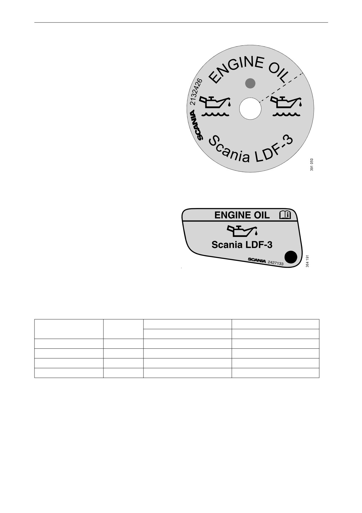
Labels for filled engine oil grade
When changing oil it is important to use the cor-
rect engine oil grade. The oil filler should there-
fore be clearly marked with a label for the filled
oil grade. However, there are only labels for oils
with Scania LDF approval and oil grade
ACEA E7.
Stick on a new label if the oil type or oil grade is
changed in favour of any of the oil types above.
Replace the label if it is missing.
Filling label in the cylinder block.
Filling label in the rocker cover.
If the oil grades below are used, you can order oil
filler labels from Scania.
Oil grade
Colour
Part no.
Part no.
Filling in the cylinder block
Filling in the rocker cover
Scania LDF-3
Red
2 132 426
2 427 133
Scania LDF-2
Blue
2 132 424
-
Scania LDF
Grey
2 269 345
-
ACEA E7
White
2 132 425
2,427,132
22
Lubrication system
Oil analysis
To be able to extend the oil change intervals us-
ing an oil analysis, Scania LDF-3 and LDF-2 oils
must be used. Certain laboratories offer engine
oil analysis.
The following conditions must remain fulfilled
when the oil is changed:
• Viscosity at 100°C (212°F): max. ±20% of
original value of the fresh oil.
• TBN (in accordance with ASTM D4739):>
3.5.
• TBN (in accordance with ASTM D4739): >
TAN (in accordance with ASTM D664).
• Soot (DIN 51452):< 3%.
Such analysis measures the oil's TBN (Total
Base Number), TAN (Total Acid Number), fuel
dilution, water content, viscosity and the quanti-
ty of particles and soot in the oil.
The result of a series of analyses is used as the
basis for establishing a suitable oil change inter-
val.
If the conditions are changed, a new oil analysis
programme must be carried out to establish new
oil change intervals. Work out the new oil
change interval for the engine in conjunction
with the workshop.
REQUIREMENT!
Only Scania LDF oils may be used in conjunc-
tion with oil analysis and a possible extended oil
change interval.
Depending on the market, the warranty condi-
tions may also change if the oil change intervals
differ from the recommended Scania timetable.
23
Lubrication system
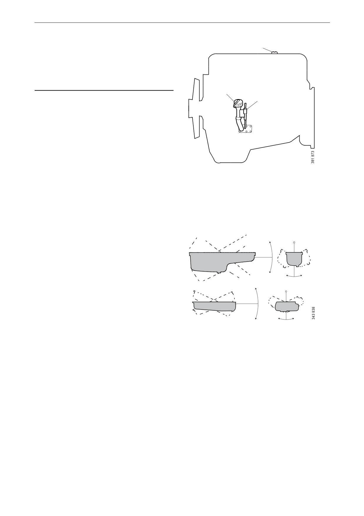
Checking the oil level
2
Note:
Leave the engine off for at least 7 minutes before
you check the oil level.
2
1
1. Remove the oil dipstick and check the oil
level. The correct level is between the mini-
mum and maximum marks on the oil dip-
stick.
2. Fill with more oil via the oil filler if the oil
level is at or below the minimum mark.
For information on the correct oil type, see the
section Oil grade.
Maximum angles of inclina-
tion during operation
Maximum permissible angles of inclination dur-
30°
ing operation vary, depending on the type of oil
sump. See illustration.
30°
30°
30°
25°
25°
30°
30°
24
Lubrication system
Changing the oil
WARNING!
Hot oil can cause burns and skin irritation. Wear
protective gloves and eye protection when
changing hot oil. Make sure that there is no pres-
sure in the lubrication system before changing
the oil. The oil filler cap must always be in place
when starting and running the engine to prevent
oil being ejected.
Note:
Change oil more often if the engine is subjected
to particularly demanding operation, such as a
dusty environment, or if deposits in the centrifu-
gal oil cleaner are thicker than 28 mm (1.1 in).
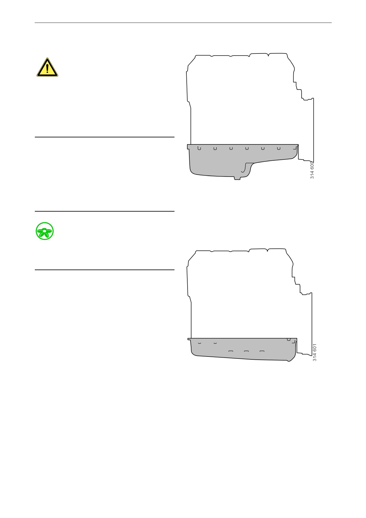
Oil volume for oil sump with deep front:
Renew the oil filter and clean the centrifugal oil
Min. 31 litres (8.2 US gallons).
cleaner when changing oil.
Max. 36 litres (9.5 US gallons).
Environment
Use a suitable container. Used oil must be dis-
posed of as specified in national and internation-
al laws and regulations.
1. Unscrew the oil plug and drain the oil when
the engine is hot. In certain engine types the
oil is pumped out by means of a bilge pump.
If the engine is drained via the valve, the oil
should be hot. Alternatively, use a pump.
This so that draining occurs more quickly.
2. Wipe off the magnet on the oil plug.
3. Renew the gasket on the oil plug.
4. Refit the oil plug.
5. Fill with the amount of oil specified for the
Oil capacity for low oil sump:
oil sump.
Min. 28 litres (7.4 US gallons).
6. Wait at least 7 minutes.
Max. 35 litres (9.2 US gallons).
7. Check the level on the oil dipstick.
25

Lubrication system
Cleaning the centrifugal oil
cleaner
WARNING!
The oil may be hot. Carefully remove the cover
from the centrifugal oil cleaner.
Use eye protection and protective gloves when
working on the centrifugal oil cleaner.
When the centrifugal oil cleaner is cleaned, there
should be some dirt deposits on the paper in the
rotor cover. If the paper is clean, the equipment
is not working as it should. If this is the case, in-
vestigate the cause of this.
Renew the paper more frequently if the dirt de-
posits are thicker than 28 mm (1.1 inches) during
a scheduled oil change.
1. Clean the cover.
2. Unscrew the nut securing the outer cover.
3. Let the oil run out from the rotor.
x 1.5
4. Lift out the rotor. Wipe off the outside.
5. Undo the rotor nut and unscrew it about
1.5 turns.
Note:
Take care not to damage the rotor shaft.
26
Lubrication system
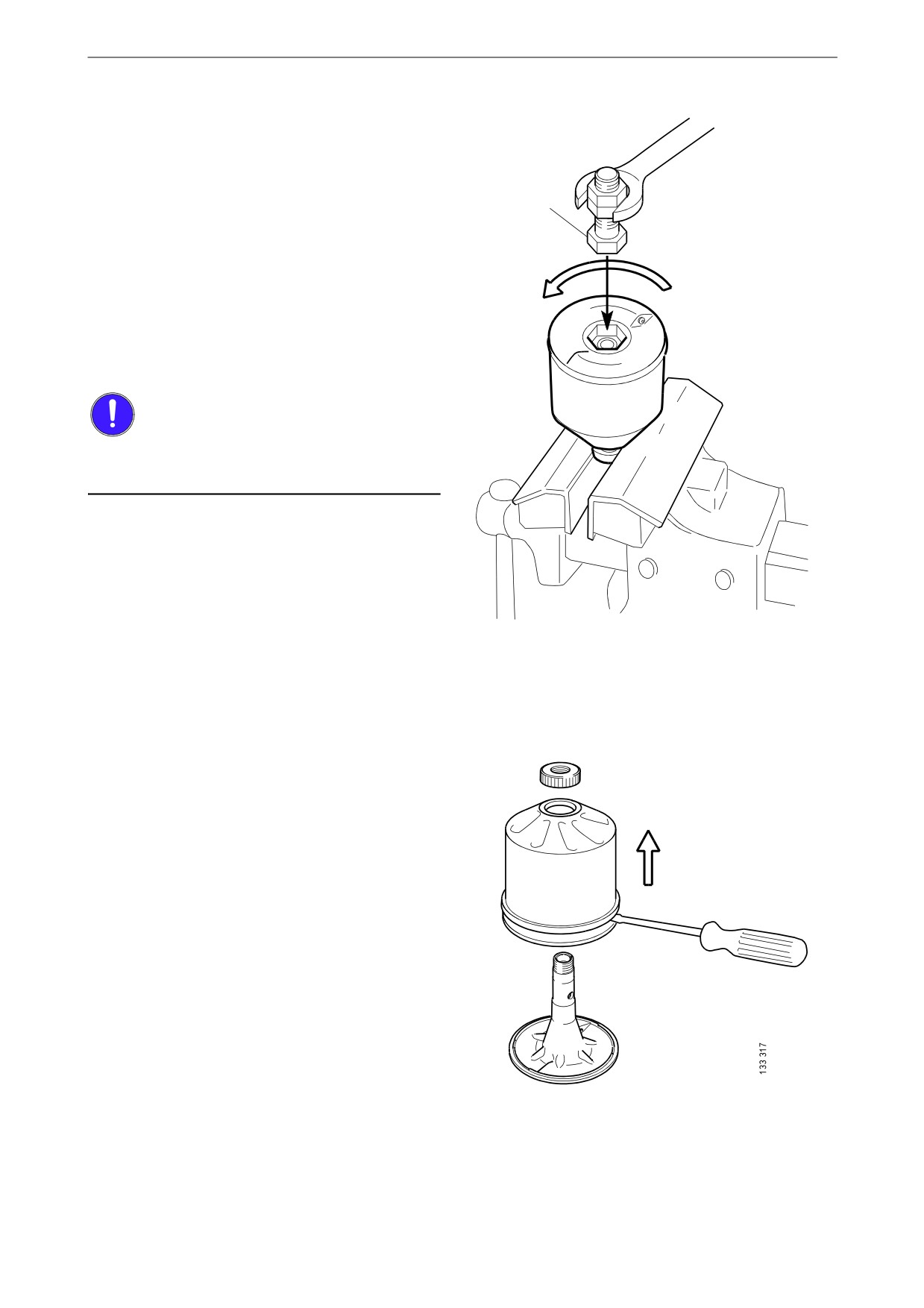
6. If the rotor nut is jammed: Turn the rotor up-
side down and fasten the rotor nut in a vice.
See illustration.
7. Use protective jaws so as not to damage the
M20
grooves of the rotor nut.
8. Turn the rotor 1.5 turns anti-clockwise.
9. If this does not work: Screw two nuts togeth-
er with an M20 screw.
10. Position the screw head at the bottom of the
rotor.
x 1.5
11. Position a ring spanner on the lower nut and
turn the rotor 1.5 turns anti-clockwise.
IMPORTANT!
Do not attach the rotor directly to the vice. Never
strike the rotor cover.
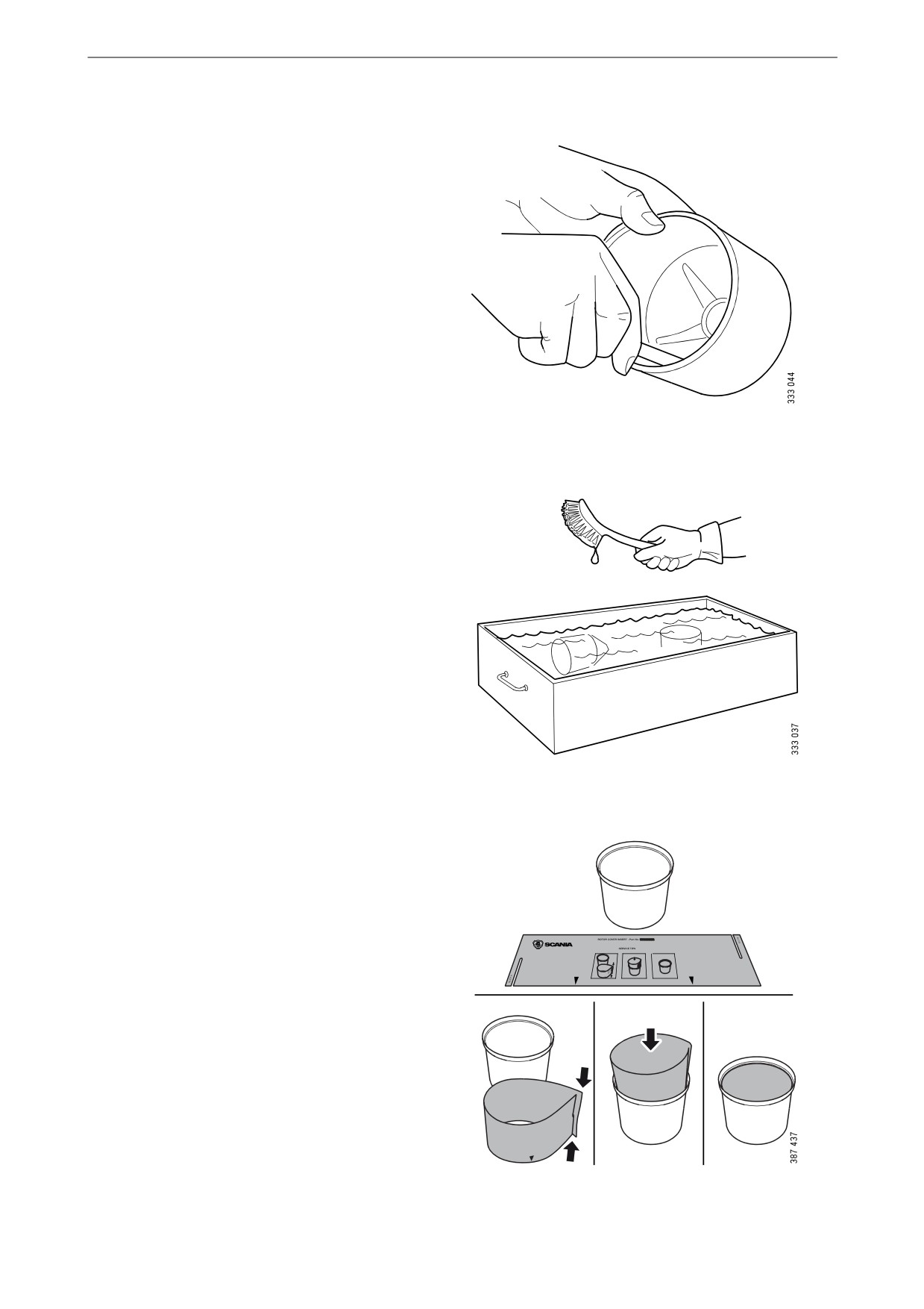
12. Remove the rotor cover by holding the rotor
in both hands and tapping the rotor nut
against the table. Never strike the rotor di-
rectly as this may damage its bearings.
13. Remove the strainer from the rotor cover. If
the strainer is stuck, insert a screwdriver be-
tween the rotor cover and strainer and care-
fully prise them apart.
27
Lubrication system
14. Remove the paper insert.
15. Scrape off any remaining dirt deposits from
the inside of the rotor cover. If the deposits
on the paper are thicker than 28 mm (1.1 in),
the centrifugal oil cleaner must be cleaned
more often.
16. Wash the parts according to the applicable
industrial method.
17. Inspect the 2 nozzles on the rotor. Ensure that
they are not blocked or damaged.
Renew any damaged nozzles.
18. Check that the bearings are undamaged.
Renew damaged bearings.
1
19. Fold and fit a new paper insert on the inside
of the rotor cover as illustrated.
2
3
4
28
Lubrication system
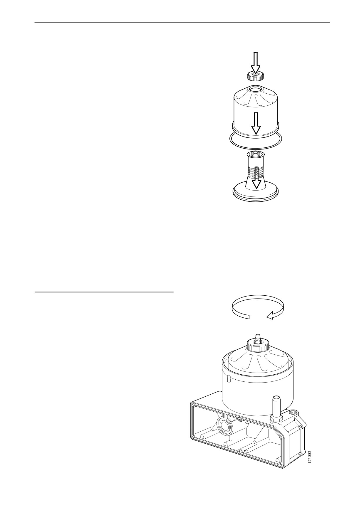
20. Fit the strainer onto the rotor.
21. Fit a new O-ring to the foot of the centrifugal
oil cleaner.
22. Refit the rotor cover. Ensure that the O-ring
is not outside the edges, but is in the groove.
23. Screw the rotor nut back on by hand.
24. Check that the shaft is not damaged or loose.
Contact a Scania workshop if the rotor shaft
needs renewing.
Note:
Take care not to damage the rotor shaft.
25. Refit the rotor and rotate it by hand to make
sure it rotates easily.
29

Lubrication system
26. Fit a new O-ring in the cover.
27. Refit the cover and tighten the lock nut.
Tightening torque 20 Nm (15 lb-ft).
IMPORTANT!
To reduce the risk of oil leakage it is important to
tighten the cover to the correct tightening torque.
Operational testing of the
centrifugal oil cleaner
Operational testing need only be carried out if it
is suspected that the centrifugal oil cleaner is
malfunctioning. For example, if there are unusu-
ally few deposits given the distance driven.
1. Run the engine until it reaches normal oper-
ating temperature.
2. Turn off the engine and listen for the sound
from the rotor. It should continue rotating for
a time, even when the engine has stopped.
3. Use your hand to feel if the filter housing is
vibrating.
4. If the filter housing is not vibrating, disman-
tle and check the centrifugal oil cleaner.
30
Lubrication system
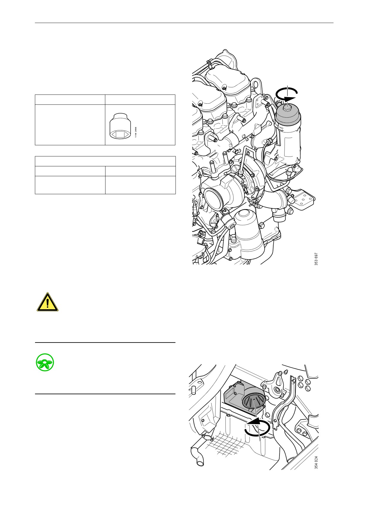
Renewing the rotor in down-
wards-moving centrifugal oil
cleaners (option)
Tool
Description
Illustration
Hexagon socket, 1/2",
36 mm
Tightening torques
Oil filter cover
25 Nm (18 lb/ft)
Centrifugal oil cleaner
70 Nm (52 lb/ft)
cover
1. Run the engine until it reaches normal oper-
ating temperature.
2. Drain the lubrication system as follows:
- Detach the oil filter cover with the tool.
- Allow the lubrication system to drain for
approximately 2 minutes.
- Renew the oil filter.
- Refit the oil filter cover.
3. Clean the area around the centrifugal oil
cleaner.
WARNING!
When the bottom cover is detached, a small
amount of oil will always run out. Beware of hot
oil. Wear protective gloves and goggles.
Environment
Use a waste oil trolley when the centrifugal oil
cleaner is drained.
4. Unscrew the bottom cover of the centrifugal
oil cleaner 2 turns without removing the cov-
er. Start from the mark on the cover.
31