Scania D11, DI11. Marine engine. Operator’s manual - part 2


  Index      Scania     Scania D11, DI11. Marine engine. Operator’s manual


Search            copyright infringement  


Content      ..      1      2      3      ..


Scania D11, DI11. Marine engine. Operator’s manual - part 2


1997-11:2

17

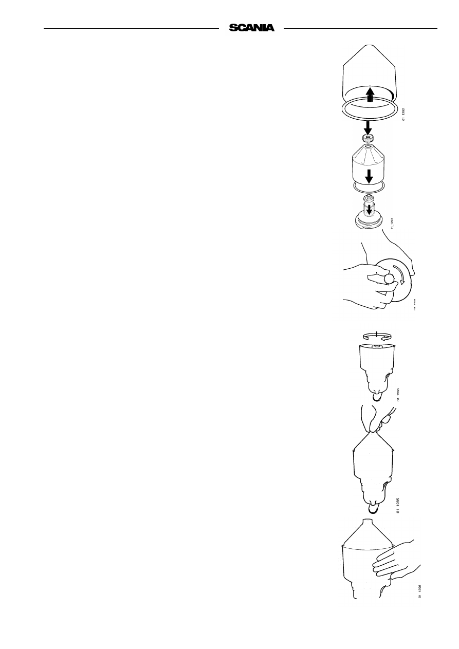
- Wash all parts in diesel fuel oil. 

- Place the O-ring in position in the rotor bowl. This must not be 

damaged.
Change if necessary.

- Assemble the rotor 

- Tighten the rotor nut hard by hand 

- Refit the rotor. 

- Check that it turns easily.

- Check that the O-ring in the bowl is not damaged.

A hardened or damaged O-ring should be replaced.

- Screw down the bowl hard by hand

If the nut is tightened using a tool, the rotor shaft, nut or bowl may be 
damaged.

Operational test 

The rotor turns very quickly and should continue to rotate when the engine 
has stopped.

- Stop the engine when it is warm.

- Listen for the whirring from the rotor or feel whether the cleaner hous-

ing is vibrating.

The rotor normally rotates 30 - 60 seconds after the engine has stopped.

If not: Dismantle and check.

18

1997-11:2

4. Every 400 hours: 

CHANGING THE TURBO FILTER    

(at the same time as the oil change) 

- Remove the old filter and discard it according to environmental require-

ments.

- Oil the rubber gasket a fit a new Scania genuine filter.

- Tighten the filter by hand.

Never use tools as the filter may sustain damage, interfering with cir-
culation.

- Start the engine and check for leaks.

If the deposits in the centrifugal cleaner exceed 20 mm, the turbo filter 
must be changed more often, at the same time as cleaning the centrifugal 
filter and changing the oil.

COOLING SYSTEM 

5. Daily:

CHECKING COOLANT LEVEL

- Open the expansion tank cap and check coolant level.

-   Correct level: (integrated expansion tank in heat exchanger)  

- Cold engine:  Coolant level should be between 10 - 20 mm below


the expansion tank’s inner upper part. 

- Warm engine: Coolant level reach the expansion tank’s


inner upper part. 

- Other types of expansion tank according to the installer’s instructions.

- Top up coolant as necessary, see point 6.

Note

When filling large amounts of coolant:
Never pour cold coolant into a warm engine.
This could crack the cylinder block and head.

Always top up using pre-

mixed coolant.

WARNING 

Open the cover carefully.

 water and steam can

 spray out.

1997-11:2

19

6. Every 400 hours: 

CHECKING CORROSION PROTECTION 
RODS 

(Only engines with heat exchanger) 

- Drain the seawater circuit and check the corrosion protection rods 

(sacrificial anodes). Location as per drawing on page 5. 

- Scrape away all loose material from the anode. 

- Change if less than half the rod remains.

New rods are 55 mm long, diameter 17 mm. 

If the corrosion protection rods are highly eroded, they should be checked 
more often, e.g. every 200 hours. 

7.   Every 400 hours: 

CHECKING SEAWATER PUMP 
IMPELLER 

(Only engines with heat exchanger) 

- Close the bottom valve if the seawater pump is below the water line. 

- Drain the seawater circuit. 

- Remove the cover from the seawater pump. 

- Check that the impeller vanes are not worn or damaged. 

If the impeller often requires changing, it is necessary to improve
the purity of the seawater. 

Changing the impeller 

- Extract the impeller using extractor 98 482 (Scania special tool). 

- Fit new impeller and the cover. Check that the cover seal is not hard or 

damaged. 

Note

A spare impeller should be carried onboard. 

- The impeller can become deformed after long periods of standstill. 

Change before starting or remove the impeller before long periods of 
disuse. Also see “Mothballing”. 

20

1997-11:2 

8. Every 2,400 hours: 

CHECKING COOLANT 

Coolant should be checked as follows:

a)

Check the appearance of the coolant.

b)

Coolant with glycol: Check the glycol content.

c)

Coolant with Scania Anti-corrosive:
Check the protection against corrosion.

The composition of the coolant is also described under
 “Starting and running”

a) 

Checking the appearance of the coolant

- Take a little coolant in a vessel and check that it is clean and clear.

- If the coolant is contaminated or cloudy: Consider changing the coolant

- The water for the coolant should be free of dirt.

- Use drinking water with a pH of 6 - 9.

b) 

Checking glycol content

If there is a danger of freezing, use only glycol as protection against corrosion 
in the coolant.

- Cooling systems with glycol must contain at least 30% glycol by 

volume to offer sufficient protection against corrosion.

- 30% glycol by volume provides anti-freeze protection down to -18 °C. 

If more protection is required, see the table on the next page for calcula-
ting the necessary amount of glycol.

We recommend only nitrite-free glycol anti-freeze with the following supp-
lier designations: 

BASF G48 or BASF D542

- Always top up the anti-freeze if the content drops below 30% by 

volume. A glycol content above 60% by volume will not improve the 
protection against corrosion.

- The table shows the temperature at which ice (slush) starts to form. The 

engine freezes and breaks at significantly lower temperatures, see graph.

- Ice forming in the coolant often causes malfunction without any risk of 

damage. The engine must not be loaded hard when ice is forming.

Note

The coolant should be changed when the cooling system is clea-
ned: Every 4,800 hours or at least every 5th year.

Important

If a coolant filter is used in the cooling system, it must not con-
tain an inhibitor.

Coolant composition: 

If there is a danger of freezing: 

at least 30% glycol by volume, 

max. 60% glycol by volume 

If there is no danger of 

freezing: 

7-12% by volume

 Scania Anti-corrosive 

The coolant should be mixed 

before it is poured into the 

cooling system.

Never top up with only water 

or only glycol.

WARNING 

Ethylene glycol is

 toxic if ingested.

Avoid contact with the skin.

The recommended glycols 

must not be mixed with glycol 

which has nitrite-based anti-

corrosive.

This could cause sludging and 

reduced cooling capacity.

1997-11:2

21

A= Range to be avoided. Only for calculation of glycol mix.

Freezing point of coolant when ice slush starts to form at different glycol mixes

% Glycol 
by volume    

15


20     

25     

30     

35     

40     

45     

50     

Cooling 

system

 capacity, 

dm

3     

Ice slush starts 
to form at °C     

-7      -10


-14

     -18 

    -24 

    -30 

    -38 

    -40 


Glycol dm

3


(litres)    

5     

6     

8     

9     

11     

12     

14     

15     

30         

6     

8     

10     

12     

14     

16     

18     

20     

40         

8     

10      13     

15     

18     

20     

23     

25     

50         

9     

12      15     

18     

21     

24     

27     

30     

60         

11     

14      18     

21     

25     

28     

32     

35     

70         

12     

16      20     

24     

28     

32     

36     

40     

80         

14     

18      23     

27     

32     

36     

41     

45     

90         

15     

20      25     

30     

35     

40     

45     

50     

100         

17     

22      28     

33     

39     

44     

50     

55     

110         

18     

24      30     

36     

42     

48     

54     

60     

120         

20     

26      33     

39     

46     

52     

59     

65     

130         

21     

28      35     

42     

49     

56     

63     

70     

140         

23     

30      38     

45     

53     

60     

68     

75     

150         

24     

32      40     

48     

56     

64     

72     

80     

160         

26     

34      43     

51     

60     

68     

77     

85     

170         

27     

36      45     

54     

63     

72     

81     

90     

180         

29     

38      48     

57     

67     

76     

86     

95     

190         

30     

40      50     

60     

70     

80     

90      100     

200     

% Glycol by volume

Cold characteristics of glycol:

- Example with 30% glycol by volume

- Ice slush starts to form at -18 °C.

- At -30 °C there is a risk of malfunction

- The engine cannot be damaged if there is at 

least 30% glycol by volume

Line A:

Ice starts to form (slush)

Line B:

Temperature at which engine freezes 
and breaks

1. Safe range

2. Malfunction can arise (ice slush)

3. Coolant frozen

22

1997-11:2 

c) 

Checking Protection against corrosion 

There must always be sufficient anti-corrosive (inhibitor) in the coolant to 
protect the cooling system against corrosion.

If there is no danger of freezing use only Scania Anti-corrosive

The inhibitor in Scania Anti-corrosive is nitrite-free.

The correct level of anti-corrosive is 7-12% by volume

- Fill with Scania Anti-corrosive as indicated on the packaging. 

- Topping up with 1.0% by volume of Scania Anti-corrosive should be 

done after every 2,400 operating hours. 

- Never top up with water only or anti-corrosive only. Lost fluid should 

always be replaced with pre-mixed coolant:
water + 10% Scania Anti-corrosive by volume. 

Note

The coolant should be changed when the cooling system is clea-
ned: every 4,800 hours or at least every 5th year.

Changing coolant    

1.

Remove the filler cap from the expansion tank.

2.

The coolant is drained at two points:

- the ”lowest point” of the engine block, see drawing

- the ”lowest point” of the cooling system.

3.

Close the valves.

4.

Fill coolant through the expansion tank filler hole.

Mix coolant as described on page 20. 

Scania Anti-corrosive must not 

be mixed with glycol. 

Mixing or over concentration 

can cause sludging and 

reduced cooling capacity.

Any coolant filter must not 

contain inhibitor. 

1997-11:2

23

9.


Every 4,800 hours: 

CLEANING COOLING SYSTEM 

Note

If necessary, the cooling system should be cleaned more often.

External cleaning

Heat exchanger

1.

Drain the coolant from the engine, see “Changing coolant”. 

2.

Drain the seawater circuit. 

3.

Detach the heat exchanger hose and pipe connections. 

4.

Dismantle the heat exchanger as illustrated. 

5.

Clean the outside of the element. Use a paraffin-based engine cleaner. 

6.

Any deposit on the inside of the pipes is removed mechanically using a 
round file. 

7.

Assemble the heat exchanger. Change damaged and hardened O-rings. 

8.

Refit hose and pipe connections.

9.

Fill the system with coolant as described in the specifications on 
page 20. 

1.

Heat exchanger  
housing 

5.

Cover 

6.

Gasket 

7.

Screw 

8.

Cooling element 

9.

O-ring 

10.

Gasket 

11.

O-ring
(DS only) 

12.

Cover 

13.

Gasket 

14.

Screw 

15.

Washer 

16.

Cover

17.

O-ring 

18.

Screw 

19.

Washer 

20.

O-ring 

21.

Protective anode 
(4 pcs) 

22.

Plug 

23.

Gasket 

24.

Pressure cap 

28.

Cover (DS only) 

29.

Gasket 
(DS only) 

30.

Screw (DS only) 

The cooling system must not

 be cleaned using caustic soda.

Risk of damaging

 aluminium parts.

Note 

There is a spring and a 

retainer in the heat exchanger, 

between the housing and the 

element, which are not 

illustrated. 

24

1997-11:2 

 Charge air cooler (DSI engine)


1.

Drain the coolant from the engine, see “Changing coolant”. 

2.

Detach the upper part of the intake manifold.

3.

Detach the charge air cooler hose and pipe connections.

4.

Dismantle the charge air cooler as illustrated.
Take care not to damage the element’s water connections.

5.

Clean the outside of the element. Use a paraffin-based engine cleaner. 

6.

Assemble the charge air cooler. Change all seals and gaskets.

7.

Refit hose and pipe connections.

8.

Fill coolant as described on page 20.

9.

Connect the intake manifold from the turbo.

1.

Intake manifold, lower 
part 

2.

Gasket

3.

Radiator element

4.

Gasket

5.

Intake manifold, upper 
part

6.

V-ring seal

Engines without heat exchanger (keel-cooling) 

1.

Check cooling elements/cooling pipes on the inside and outside of the 
keel. 

2.

Clean as necessary using a paraffin-based engine cleaner or carefully 
scrape off deposits from external pipes. 

Take care - do not damage cooling elements or cooling pipes. 

The cooling system must not 

be cleaned using caustic soda.

Risk of damaging aluminium 

parts.

1997-11:2

25

Internal cleaning 

Removing oils and greases

- If possible, run the engine until it is warm and then drain the cooling 

system.

- Remove the thermostat(s).

- Fill the system with clean, hot water mixed with liquid dishwasher 

detergent designed for household machines.
Mix 1% (0.1/10 l).

- Run the engine until warm (about 20 or 30 minutes). Do not forget any 

cab heating system.

- Drain the cooling system.

- Fill the system again using clean, hot water and run the engine for about 

20-30 minutes.

- Drain the water from the system.

- Refit the thermostat(s).

- Fill the system with coolant as described in the specifications on 

page 20

Removing deposits

- If possible, run the engine until it is warm and then drain the cooling 

system.

- Remove the thermostat(s).

- Fill the system with clean, hot water mixed with one of the commerci-

ally available radiator cleaners based on sulphamin acid and containing 
dispersing agents. Follow the manufacturer’s instructions for mix ratios 
and cleaning times.

- Run the engine for the for the specified time and then drain the cooling 

system.

- Fill the system again with hot water and run the engine for about 20 or 

30 minutes.

- Drain the water from the system.

- Refit the thermostat(s).

- Fill the system with coolant as described in the specifications on 

page 20. 

WARNING 

When handling cleaners for 

the cooling system:

Study the warning on the 

packaging.

26

1997-11:2 

AIR CLEANER 

10. Daily:

TEST READING
LOW PRESSURE INDICATOR

If the indicator’s red plunger is fully visible, change or clean the air cleaner
filter insert, point 12.

11. Every 200 hours: 

CLEANING THE AIR CLEANER
COARSE CLEANER

1.

Detach the eccentric catch and remove the coarse cleaner. 

2.

Remove the plastic cover from the coarse cleaner and clean the parts. 

3.

Check that the plastic cover is intact and that it makes a seal against the 
air cleaner housing during assembly. 

4.

Assemble the air cleaner 

12. Every 1,200 hours: 

CLEANING OR CHANGING
FILTER INSERT

Note

Earlier if low pressure indicator shows red

Dismantling

1.

Remove and clean the coarse cleaner, see point 11.

2.

Undo the nut securing the filter insert and remove it. 

3.

Change or clean the insert.

Note

Cleaning the insert always means a risk of damage. The insert 
may only be cleaned no more than four times
After cleaning, it 
has a lower dust capacity than a new insert. 

4.

Mark the filter when it has been cleaned.

Cleaning insert

- Carefully blow the filter insert clean using dry compressed air from the 

inside.

Note

This insert must not be washed using water.

Use only Scania genuine 

air filter.

Change damaged filter 

inserts.

Major risk of engine 

damage if the filter insert is 

damaged.

1.

Pre-filter with cover

2.

Filter insert

3.

Low pressure indicator

4.

Safety cartridge

The coarse cleaner should 

be fitted with the marking 

“TOP” facing up.

1997-11:2

27

Checking 

- Insert a flashlamp into the insert and check from the outside that there 

are no holes or cracks in the filter paper.

- Change the filter insert if there is any damage at all. Danger of engine 

damage.

Assembly

1.

Assemble the air cleaner in reverse order.

2.

Reset the red plunger in the low pressure indicator by pressing in the 
button

Filters with non-replaceable insert (unit cleaner)


Cleaning 

- The filter must be cleaned no more than 3 times. Make a mark on it each 

time it is cleaned. 

- Use a solution of water and 1% mild detergent     

1.

Pour the washing solution into the filter intake while turning the filter so 
that the solution runs out of it in the direction of air flow. 

2.

Leave the filter in the washing solution for 5 minutes and then lift it to 
drain off the solution 

3.

Rinse the filter with about 30 litres of clean water at 30 - 40 °C. Pour the 
rinse water into the filter in the same way as the washing solution. 

4.

Lift the filter and allow the rinse water to drain. 

5.

Repeat this procedure until the rinse water runs clear. 

6.

Leave the filter to dry in a warm place for several days. 

Note

The filter must not be blown dry using compressed air.  

28

1997-11:2 

13. Every 2,400 hours: 

CHANGING SAFETY CARTRIDGE

1.

Remove and clean the coarse cleaner, see point 11.

2.

Undo the nut securing the filter insert and remove it. 

3.

Change or clean the filter insert, see point 12.

4.

Undo the nut securing the safety cartridge and remove it. 

5.

Fit a new Scania genuine safety cartridge. 

6.

Assemble the air cleaner. 

Never clean the safety 

cartridge. 

Do not remove the safety 

cartridge unnecessarily. 

1.

Pre-filter 

with cover

2.

Filter insert

3.

Low pressure indicator

4.

Safety cartridge

1997-11:2

29

FUEL SYSTEM 

14. Daily:

CHECKING FUEL LEVEL 

- Top up fuel if necessary.

- If the tank is run dry, bleed the fuel system, see point 15.

Be extremely careful with 

cleanliness when working on 

the fuel system.

Malfunctions

 can easily arise and the 

injection equipment

 can be damaged. 

15.


 Every 1,200 hours:

CHANGING THE FUEL FILTER

Fuel tanks

- Drain any water from the fuel tanks.

Main filter 

The filter consists of two parallel coupled filter units. 

- Wash the outside of the filters and unscrew them. Dispose of the filters 

according to environmental regulations. 

- Do up the new filter by hand

Never use tools. The filters may be damaged, inhibiting circulation. 

- Bleed the fuel system as below.

- Start the engine and check for leaks.

Bleeding the fuel system

- Open the bleed screw 1 on the main filter. 

- Pump the hand pump 2 until air-free fuel flows out at the maim bleed 

screw. 

- Close the bleed screw. Pump a few times using the hand pump. 

If the engine is difficult to start after bleeding . . . . .  

- Slacken the injection pump overflow valve 3 one half turn

and try starting again. On the 8000 pump, the overflow valve is located 
on the fuel shut-off valve. 

If the engine still won’t start . . . . . . . 

- Pump the hand pump until bubble-free fuel flows from the overflow 

valve.

Tighten the overflow valve when the engine has started. 

Use only Scania genuine 

fuel filter 

30

1997-11:2 

16. Every 2,400 hours: 

CHECKING INJECTORS

Injectors should be inspected by trained personnel with access to the required 
equipment, at least once every year or every 2,400 hours. 

Removal

1.

Clean around the injectors and connections including the clamps and 
brackets. 

2.

Detach the delivery pipe bundle and the leak-off fuel lines. 

3.

Unscrew the injector. 

4.

Place protective plugs on the injector and delivery pipe. 

5.

Lift the seal from the bottom of the injector seat if it does not come out 
together with the injector. 

6.

Place a seal plug in the injector seat in the cylinder head. 

7.

Clean the injectors and check/adjust in an injector tester. 

Correct opening pressure, see Technical data, page 43

Fitting 

1.

Check that there is no old seal in place and fit a new seal in the bottom 
of the injector seat.

2.

Fit a new O-ring in the socket nut and a new seal under it. 

3.

Fit the injector. 

4.

Tighten the socket nut to 70 Nm (7.0 kpm). 

5.

Fit the delivery pipe and tighten the cap nuts to 20 Nm
(2.0 kpm). Fit clamps and brackets. 

Take care to fit the delivery pipe without tension and make sure that


the cone on the delivery pipe is correctly positioned in the connector. 

6.

Fit the leak-off fuel line. Tighten the bolts to 11 Nm (1.1 kpm). 

1.

Delivery pipes 

2.

Cap nut 

3.

Washer 

4.

Cone 

5.

Connector on injector or 
injection pump 

Delivery pipe connection 

1.

Socket nut 

2.

O-ring 

3.

O-ring 

4.

Stop ring 

5.

Guide pin 

6.

Seal 

The delivery pipes must not 

be bent. 

All clamps must be refitted. 

1997-11:2

31

ELECTRICAL SYSTEM 

17. Every 200 hours: 

CHECKING ELECTROLYTE LEVEL
IN BATTERIES 

1.

Undo the plugs and check the electrolyte level in all cells. 

2.

Top up using distilled water until the level is 10-15 mm above the plates. 

18. Every 200 hours: 

CHECKING CHARGE STATE 
IN THE BATTERIES 

Note

Every 200 hours applies to gensets and the like. Other installa-
tions every 1,200 hours. 

- Check specific gravity using a battery electrolyte tester. 

In a fully charged battery it should be: 

1,280 at +20°C 

1,294 at 0° 

1,308 at -20°C 

- If the specific gravity is below 1.20, the battery must be charged.

A discharged battery freezes at -5 °C. 

Avoid boost charging. This will damage the battery in the long term. 

19. Every 200 hours: 

CLEANING BATTERIES 

Note

Every 200 hours applies to gensets and the like.Other installa-
tions every 1,200 hours. 

1.

Clean batteries, cables and cable terminals. 

2.

Check that all cable terminals are well tightened. 

3.

Grease posts and cable terminals using petroleum jelly. 

32

1997-11:2

20. Every 1,200 hours:

CHECKING COOLANT
LEVEL MONITOR 

(optional equipment) 

1.

Start the engine. 

2.

Check the level monitor by turning the ”TEST” knob to the right. 

3.

Automatic stop in case of fault: Engine stops, warning lamp lights and 
buzzer sounds if there is no fault in the level monitor. 

4.

No automatic stop in case of fault: Warning lamp lights, buzzer sounds 
if there is no fault in the level monitor. 

C = Common connection 

NC =Connection NC - C breaks at 

low coolant level 

NO =Connection NC - C closes at 

low coolant level 

2-pole level monitor 


Content      ..      1      2      3      ..