Scania DI12, DC12. Industrial engine. Operator’s manual - part 2


  Index      Scania     Scania DI12, DC12. Industrial engine. Operator’s manual


Search            copyright infringement  


Content      ..      1      2      3      ..


Scania DI12, DC12. Industrial engine. Operator’s manual - part 2


2001-05:1

17

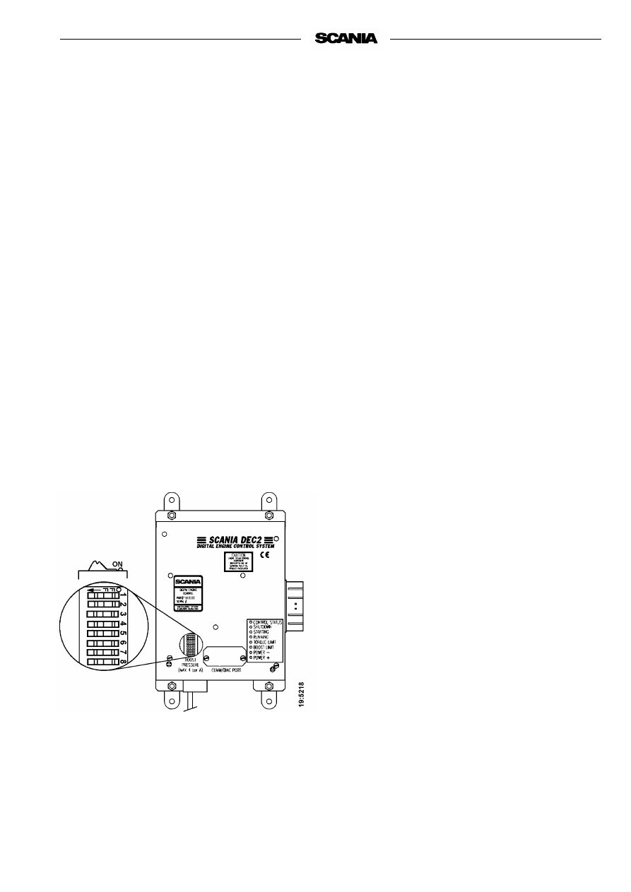
Changing functions using the DIP 
switches in the control unit

There are 8 DIP switches in the control unit under the 
round black rubber cover.

These switches shall be in the ON position to obtain 
normal functions according to the operating program. 
However, for single-speed engines, the normal 
position of DIP switches 6, 7, and 8 may also be OFF

Shutdown at threshold values for low oil pressure and 
high coolant temperature can be selected by setting 
DIP switch 4 to OFF

With DIP switch 4 in position ONPower- indication 
is obtained for these threshold valuesEngine output 
reduction (LOP) can be selected to prevent damage to 
the engine. Changes to the program must only be 
performed by authorized personnel.

Note:

Do not operate the engine with a Power- 
indication except for in emergencies.

Readout of fault codes

Note:

If the engine has stopped or lost power but 
the main indicator lamp is out and neither 
POWER- nor SHUTDOWN are on, the fault 
is outside the control unit detection range. 
Probable causes: fuel shortage, temporary 
overload, mechanical fault.

- Activate the lamp test/fault code switch. In 

Scania electrical equipment the main indicator 
lamp is located in this switch on the main supply 
box.

- All LEDs will then come on for 2 seconds to 

indicate that they are intact and in working order. 
This also applies to the main indicator lamp in the 
main supply box and the instrument panel

.

 Make 

a note of any LED that is defective.

- All LEDs will then be out for approximately 4 

seconds.

- Following this, a fault code will be indicated on 

one of the LEDs for 2 seconds. Note which LED 
it is.

- The control unit then resumes the operating mode 

automatically.

- After having made a note of the fault code, reset 

the lamp test/fault code switch and reset the 
control unit by turning off its power supply 
momentarily.

- The most probable cause of the fault can then be 

found in the trouble shooting schedule on the next 
page.

- When the fault or faults have been rectified the 

engine can be restarted.

- If the control system continues to indicate a fault 

by way of the main indicator lamp, further faults 
may have been recorded. The fault code readout 
must then be repeated as per above since the 
system can only display one fault code at a time.

- The fault(s) will be stored in a special memory in 

the control unit along with information about the 
operating time when it(they) occurred. Stored 
faults can be accessed and erased by authorised 
service personnel.

18

2001-05:1

READOUT OF

 F

A

UL

CODES

LE

D INDI

CA

TION WHE

N

 THE

 LAMP T

E

S

T

/F

AUL

T CODE SWITCH IS AC

TIV

A

TED

CON

TROL ST

AT

US

SHUTDOWN 

STA

RT

ING


RUNNING 

TO

RQUE LIM

IT 

BOOS

T LIMIT


POWER -

POWER +

Pr

obabl

e ca

use

A

ct

io

n

DEC2 ha

s de

te

ct

ed a

n

 in

te

rna

l f

aul

in t

h

e con

tr

o

l u

n

it

.

Send 

in t

he

 cont

rol u

nit

 f

or r

e

p

a

ir

 as

 soo

n as


poss

ib

le.

The

 engi

ne

 te

m

p

era

tu

re h

as 

rea

che

d t

h

e t

h

resho

ld 

lev

el


or

 th

e t

e

mper

at

ure

 se

nsor

 i

s i

nope

rat

ive.

Check

 th

e co

oli

ng s

yst

em. Che

c

the

 te

m

p

era

tu

re 

se

ns

o

r a

n

d c

a

bl

e

 r

o

ut

in

g

.

The

 engi

ne

 has

 re

ach

ed t

he o

ver

re

vvi

ng l

imi

t or

 t

he 

eng

ine

 sp

eed 

sen

sor

 is

 in

oper

a

ti

v

e

.

Check

 th

e wir

ing an

d co

nnec

tor

.

Renew t

he

 engi

ne

 spe

e

d s

e

ns

or.

Cont

ro

l r

ack

 pos

it

ion

 se

nsor

 i

nope

rat

iv

e

.

C

heck

 con

nect

or

s a

nd c

a

bl

es t

o g

over

nor

.

The

 int

ak

e ai

tem

p

er

at

ur

e h

as r

ea

che

d th

e t

h

re

sho

ld 

le

vel

 or

 th

e c

h

ar

ge a

ir

 te

mper

at

ure

 se

nsor

 i

s i

nope

rat

iv

e.

Check

 th

e i

nta

ke s

yst

em. Che

c

k t

he

 te

m

p

era

tu

re 

se

ns

o

r a

n

d c

a

bl

e

 r

o

ut

in

g

.

DEC2 de

te

cts

 no 

char

ge

 ai

r pr

es

sur

e

.

The

 cha

rge

 ai

r pr

es

sur

e s

ens

or 

is 

ino

p

er

at

ive

.

Check

 th

e ch

arg

e

 ai

r pre

ssu

re

 hos

e. Se

nd i

n t

he 

cont

ro

l u

n

it

 fo

r r

epa

ir

 if

 t

h

e c

onne

ct

ion

 is

 damag

ed.

Engi

ne

 spe

e

d po

te

nti

omet

e

r or

 the

 id

li

ng s

a

fe

ty

 swi

tch


is

 in

ope

rat

iv

e.

Check

 th

e ca

ble

 ro

uti

ng,

 conn

ect

or

s an

d ca

bl

es.

The

 oil

 pr

es

sur

e

 ha

s dr

opp

ed t

o t

he t

hr

e

sh

old

 le

vel

 or


th

e oi

pre

ssu

re 

m

o

nit

o

r is

 in

oper

at

iv

e.

Check

 oi

l l

e

ve

l, c

onne

ct

or 

and c

a

bl

e.

Renew t

he

 oil

 pr

es

sur

e

 moni

to

r.


=

LED on 

2001-05:1

19

STARTING AND RUNNING

AT FIRST START

When the engine is started for the first time, follow the maintenance points 
listed under "First start" in the maintenance schedule, see page 27.

Since the points are important for satisfactory operation of the engine right 
from the outset, they are also listed below.

1. Checking the oil level (refer to page 29).

6. Checking the coolant (refer to page 33).

The coolant should contain anti-corrosive to protect the cooling system 
from corrosion.

If there is a danger of freezing:

- Only anti-freeze glycol should be used in the coolant as protection 

against corrosion. We recommend only nitrite-free anti-freeze glycols 
with the following supplier designations:

BASF G48 or BASF D542

- The concentration of glycol should be 30 - 60% by volume depending 

on the ambient temperatureA content of 30 % by volume provides 
protection down to -16 °C. Refer to page 33.

- Never top up with only water or only glycol. Fluid losses must always 

be replaced with pre-mixed coolant having the same glycol 
concentration as that in the engine. If the glycol content drops, both 
anti-freeze protection and protection against corrosion are impaired.

Note:

A glycol concentration below 30% by volume will not provide 
sufficient protection against corrosion. Glycol concentrations 
higher than 60 % do not improve anti-freeze protection and have 
a negative effect on engine cooling capacity.

Coolant composition:

If there is a danger of freezing:

minimum 30% glycol by volume

maximum 60 % glycol by volume

If there is no danger of freezing:

7-12% by volume

Scania Corrosion Inhibitor

(no glycol)

The recommended glycol must 

not be mixed with glycol having 

nitrite-based anti-corrosive.

Ethylene glycol and corrosion 

inhibitor, if swallowed can be 

fatal.

Avoid contact with the skin.

20

2001-05:1

If there is no danger of freezing:

- Only Scania Corrosion Inhibitor should be used in the coolant as 

protection against corrosion. The correct corrosion inhibitor content is 
7-12% by volume and must never be less than 7% by volume. The 
inhibitor in Scania Corrosion Inhibitor is free of nitrite.

- First filling: Fill the cooling system with water + 10% by volume of 

Scania Corrosion Inhibitor. Use drinkable water with a pH value of 
6 - 9.

- Never top up with only water or only anti-corrosive! Fluid losses 

must always be replaced with premixed coolant:
water + 10 % by volume of Scania Corrosion Inhibitor.

Coolant filter (not standard equipment)

Only coolant filter without inhibitor may be used. The use of coolant filters 
increases the life of the coolant and reduces the risk of deposition corrosion.

12. Checking the fuel level (refer to page 40).

15. Checking the electrolyte level in batteries (refer to page 42).

16. Checking the state of charge in batteries refer to page 42).

18. Checking the coolant level monitor (if fitted) (refer to page 43).

19. Checking the temperature monitor (refer to page 44).

20. Checking the oil pressure monitor (refer to page 45).

21. Checking the tension of drive belts (refer to page 46).

Ethylene glycol and corrosion 

inhibitor, if swallowed

can be fatal.

Avoid contact with the skin.

Immobilise the starting device 

when working on the engine.

If the engine starts out of 

control, there is a

SERIOUS RISK

OF INJURY.

The use of too much Scania 

Corrosion Inhibitor as mixed 

with glycol may cause deposits.

If a coolant filter has been fitted 

it must not contain inhibitor.

2001-05:1

21

CHECKS BEFORE RUNNING

Before running, "Daily maintenance" as described in the maintenance 
schedule should be carried out, see page 27.

STARTING THE ENGINE

If the fuel tank has been run dry or if the engine has not been used for a long 
time, bleed the fuel system (see page 40).

For environmental reasons, your new Scania engine has been designed to use 
a smaller amount of fuel when starting. Using unnecessarily large amounts of 
fuel when starting the engine always results in the discharge of unburnt fuel.

- Open the fuel cock, if fitted.

- Declutch the engine (not engines with fixed clutch, e.g. generator sets).

- Engines with battery master switch: Switch on the power by means of 

the battery master switch.

- DEC2: If the main indicator lamp comes on or flashes when the power is 

turned on, this indicates the presence of a fault in the control system or 
engine which must be found and rectified before the engine is started. 
Refer to page16.

- Start the engine by means of the starter button or starter key.

Starting at low temperatures

Local environmental requirements must be complied with. Starting aids, 
engine heaters and/or flame start devices should be used to avoid starting 
problems and white smoke.

To limit white smoke, the engine should be run at low speed and under 
moderate load. Avoid running it longer than necessary at idling speed.

Only start the engine in a 

properly ventilated area.

When operating the engine in 

an enclosed area, an effective 

extraction device for exhaust 

gases and crankcase gases

must be used.

Never use starting spray or 

similar as a starting aid.

An explosion may occur in the 

intake pipe, which could cause 

personal injury.

22

2001-05:1

At temperatures below 0 °C:

Note:

Only use starting aids recommended by Scania.

- The starter motor may only be used for 30 seconds at a time. After that 

time it must cool for 2 minutes.

If the engine has flame start:

- Operating flame start without timer relay: Press the control button, 

which also acts as a pre-glow button (max. 20 seconds). The glow plug 
continues to glow as long as this button is depressed after the engine has 
started. Maximum time is 5 minutes.

- Operating flame start with timer relay: Press the pre-glow button (a 

maximum of 20 seconds). Release it when the engine starts. The timer 
relay keeps the glow plug glowing for 5 minutes. If a shorter glow time 
is required, press the release button. The key must be turned to the 0 
position if the start attempt fails. 

Note:

If the engine is equipped with an INTERLOCK switch, this 
switch should be depressed and held until the oil pressure has 
reached a sufficiently high level.

- Generator sets should be operated under load immediately after starting 

to avoid the risk of white smoke. This applies in particular to engines 
that have been installed without aids for heating or applying a basic 
load.

- Warm up the engine with a light load. A light load on a cold engine 

gives better combustion and faster heating than warming up with no 
load.

Maximum starter engagement 

time is 30 seconds. Risk of 

overheating. Allow starter to 

cool for 2 minutes after a 

starting attempt before 

cranking again.

2001-05:1

23

OPERATION

Check instruments and warning lamps at regular intervals.

Engine speed

The Scania tachometer is divided into sectors of different colours, as follows:

Coolant temperature 

Normal coolant temperature when the engine is running should be 70 - 90°C. 

DEC2: If the temperature is high, 98°C or above, you can select for the 
control system to reduce power output (Power -) in order to bring down the 
temperature. Refer to the DEC section on page 17.

If the temperature continues to rise, the engine will be shut down 
automatically (Shutdown) at 103°C. Refer to the DEC section on page 17.

Excessively high coolant temperature can damage the engine.

If run for extended periods under an extremely light load, the engine may 
have difficulty in maintaining normal operating temperature. However, the 
temperature will rise to a normal level again when the load on the engine is 
increased.

0-500 rpm

red area:

prohibited engine speed, 

passed when stopping and 

starting.

500-700 rpm

yellow area:

low idle.

700-2200 rpm

green area:

normal operating speed.

The engine’s operating 

speed range is controlled by 

the DEC2 control system.

2200-2600 rpm

yellow/green 

striped:

unsuitable operating speed. 

May occur when switching 

off and during downhill 

engine braking

2600-3000 rpm

red area:

prohibited engine speed

WARNING!

When driving a vehicle down a steep descent 

or in other installations, where the engine may be pro-
pelled by the vehicle motion, DEC2 will set the fuel 
feed to zero to protect against engine overspeed and 
shut down the engine. The clutch must not
 be released 
in such a situation since this may cause vital functions 
such as steering and brake system to become inopera-
tive when the engine stops.

!

Overpressure is not allowed in 

cooling systems with Scania 

radiators and expansion tanks 

made of plastic, i.e. the 

expansion tank must not be 

fitted with a pressure cap.

24

2001-05:1

Oil pressure

Max. oil pressure:

hot engine at engine speed exceeding 800 rpm 

6 bar

Normal oil pressure: 

hot engine at operating speed

3 - 6 bar

Min. oil pressure:

hot engine at 800 rpm

0.7 bar

At engine speeds below 800 rpm the gauge may indicate low oil pressure 
although no fault is present.

Oil pressures below 0.7 bar at engine speeds above 800 rpm will cause 
engine damage. The engine must be stopped immediately.

DEC2: The engine is shut down automatically if this function has been 
selected. Refer to the DEC section on page 17.

Charging indicator lamp

If the lamp comes on during operation:

- Check/adjust the alternator drive belts as described in the maintenance 

step. Refer to page 46.

- If the charging indicator lamp is still on, this could be due to an alter-

nator fault or a fault in the electrical system.

STOPPING THE ENGINE

1.

Run the engine without a load for a few minutes if it has been run 
continuously with a heavy load.

2.

Stop the engine with the stop button. Keep the stop button depressed 
until the engine is completely stationary.

3.

DEC2: Before switching off, check that the control system’s main 
indicator lamp is not on or flashing.
Refer to page 16 for troubleshooting.

4.

Engines with battery master switch: Switch the power off with the 
battery master switch. (Does not apply to emergency generator sets).

5.

Set the control switch to "0". (Does not apply to emergency generator 
sets).

High lubricating oil pressure 

(above 6 bar) is normal when 

starting a cold engine.

High lubricating oil pressure 

(above 6 bar) is normal when 

starting a cold engine.

There is danger of turbo damage 

and post boiling if the engine is 

stopped without cooling.

The power must not be switched 

off before the engine has 

stopped.

2001-05:1

25

Clutch

- See the manufacturer’s instructions for handling and operating the 

clutch.

WARNING

If the clutch output shaft is rotating (e.g. in multiple 

engine installations where other engines are running), the clutch 
can, under its own power, be drawn to the engaged position.
THIS MAY CAUSE PERSONAL INJURY and engine damage. 
For this reason, always secure the clutch in the disengaged posi-
tion if there is a risk of the output shaft starting to rotate.

CHECKS AFTER RUNNING 

- Check that the power is cut from the battery master switch and that the 

control switch is in the "0" position.

- Fill the fuel tank. Make sure that the filler cap and the area round the 

filler opening are clean to avoid contamination of the fuel.

- If there is a risk of freezing, the cooling system must be drained if it 

does not contain a sufficient amount of glycol, refer to page 33

- At temperatures below 0 °C: Prepare for the next start by switching on 

the engine heater (if fitted).

Top up engine coolant when the 

engine has been stopped after 

being started for the first time.

Immobilise the starting device 

when working on the engine.

If the engine starts out of 

control, there is a

SERIOUS RISK

OF INJURY.

26

2001-05:1

MAINTENANCE

The maintenance programme covers 24 points, divided into the following 
main groups:

Lubricating oil system  . . . . . . . . . . . . . . . . . page 28
Cooling system . . . . . . . . . . . . . . . . . . . . . . . page 32
Air cleaner  . . . . . . . . . . . . . . . . . . . . . . . . . . page 38
Fuel system . . . . . . . . . . . . . . . . . . . . . . . . . . page 40
Electrical system, monitors, batteries etc.  . . page 42
Miscellaneous . . . . . . . . . . . . . . . . . . . . . . . . page 46

The maintenance points are divided into intervals as follows: 

Daily maintenance

Maintenance before first start

Maintenance after the first 400 hours of operation

Periodic maintenance every 200 hours of operation (carried out after 200, 
400, 600, 800, etc. hours)

Periodic maintenance every 400 hours of operation (carried out after 400, 
800, 1200, 1600, etc. hours)

Periodic maintenance every 1200 hours of operation (carried out after 1200, 
2400, 3600, etc. hours)

Periodic maintenance every 2400 hours of operation (carried out after 2400, 
4800 etc. hours)

Periodic maintenance every 4800 hours of operation (carried out after 4800, 
9600, etc. hours)

Annual Maintenance

Maintenance every 5th year

ENGINES WITH FEW HOURS OF 
OPERATION

Emergency generator sets and the like that are not used regularly should be 
run on test and checked in accordance with the generator set manufacturer’s 
instructions.

Run the engine until it reaches operating temperature and then carry out the 
maintenance points below:

1. Checking the oil level.

5. Checking the coolant level.

8. Checking the vacuum sensor.

12. Checking the fuel level.

15. Checking the electrolyte level in batteries.

16. Checking the state of charge in batteries.

17. Cleaning the batteries.

22. Checking for leakage, rectify as necessary

Immobilise the starting device 

when working on the engine.

If the engine starts out of 

control, there is a

SERIOUS RISK 

OF INJURY

For engines with few operating 

hours that are not subject to 

periodic maintenance according 

to the maintenance schedule on 

page 27, maintenance should be 

carried out in accordance with 

the schedule:

"Every year"

"Every 5 years"

2001-05:1

27

MAINTENANCE SCHEDULE

1.

More often if required

2.

For engines with few operating hours, see page 26.

3.

Earlier if vacuum indicator shows red.

4.

If inhibitor has not been topped up for five years, the coolant should be changed.

Dail

y

First 

time at

Interval

At least

Firs

t sta

rt


400 h

200 h

400 h

1200

 h

2400

 h

4800

 h

Annual

ly

Ever

y 5t

h ye

ar

LUBRICATING OIL SYSTEM, page 28

1. Checking the oil level


 l 


2. Oil change

l1     


3. Cleaning the oil cleaner

l1     


4. Renewing the oil filter

l1     


COOLING SYSTEM, page 32

5. Checking the coolant level


6. Checking the coolant


l4     


7. Cleaning the cooling system

l1     


AIR CLEANER, page 38

8. Checking the vacuum sensor


9. Cleaning the coarse cleaner

l1     


10. Cleaning or renewing filter element

l3     


11. Renewing the safety cartridge


 FUEL SYSTEM, page 40

12. Checking the fuel level


 l 


13. Renewing the main filter

l1     


14. Checking the injectors


ELECTRICAL SYSTEM, page 42

15. Checking the electrolyte level in batteries


l2     


16. Checking the state of charge in batteries


l2     


17. Cleaning the batteries

l2     


18. Checking the level monitor


19. Checking the temperature monitor


20. Checking the oil pressure monitor 


MISCELLANEOUS, page 46

21. Checking the drive belt


l


22. Checking for leakage, rectify as necessary


23. Checking/adjusting valve clearance


24. Renewing (or cleaning) the valve for closed crankcase 

ventilation


28

2001-05:1

LUBRICATING OIL SYSTEM

OIL GRADE

The engine oil must at least meet the requirements for one of the following 
oil classifications:

-ACEA E3, E4 or E5

- The Total Base Number (TBN) should be minimum 12-13

(ASTM 2896).

- Check with your oil supplier that the oil meets these requirements.

- The specified oil change intervals apply provided that the fuel sulphur 

content does not exceed 0.3% by weight. If the sulphur content exceeds 
0.3 % but is maximum 1.0%, the oil change intervals must be halved 
(200 h).

- Viscosities as illustrated below.

- For operation at extremely low ambient temperature: Consult your 

nearest Scania representative on how to avoid starting difficulties.

Oil analysis 

Some oil companies can offer analysis of the engine oil. Such analysis 
measures the oil TBN (Total Base Number), TAN (Total Acid Number), fuel 
dilution, water content, viscosity and the quantity of friction particles and 
soot in the oil.

The result of a series of analyses is used as the basis for establishing a 
suitable oil change interval.

If the conditions are changed, a new oil analysis programme must be carried 
out to establish the new change interval.

Additives must not be used.

The oil should be suitable for all 
temperature variations until the 

next oil change.

-40

-30

-20

-10

0

10

20

30

40 °C

SAE 10W-30

SAE 20W-30

SAE 30

SAE 40

SAE 50

SAE 5W-30

SAE 15W-40

2001-05:1

29

1. Daily:

CHECKING THE OIL LEVEL

Note

Before checking oil level: Allow the engine to remain stopped for 
at least 1 minute.

- The correct level is between the marks on the dipstick. Top up when the 

level is at the lower mark.

- Correct type, see "Oil grade" on page 28.

Checking oil level during operation

On some engines the oil level can be checked during operation.

- Remove the oil filler cap to release the pressure in the crankcase.

- Check the level on the dipstick, correct oil level: 10 mm below the 

minimum and the maximum mark

2. Every 400 hours:

OIL CHANGE

Note

Under extremely severe operating conditions, especially in dusty 
environment or if the deposits in the centrifugal cleaner are 
thicker than 20 mm: change oil more frequently.

- Unscrew the plug and drain the oil when the engine is hot.

- In certain engines the oil is pumped out by means of a bilge pump.

- Clean the magnet on the plug.

- Refit the plug.

- Fill up with oil.

- Check the level on the dipstick.

Max. 33 dm

3

Min. 28 dm

3

1 dm

3

 = 1 litre

Maximum angles of inclination during operation 

Maximum permissible angles during operation vary, depending on the type 
of oil sump, see illustration.

Note:

Specified angles may only occur intermittently.

35°

25°

25°

35°

10 mm

10 mm

WARNING

The oil may be hot.

Wear protective gloves and 

goggles

Always use a suitable container 

to avoid spillage when

changing oil.

Dispose of used oil through an 

authorized waste disposal 

contractor.

30

2001-05:1

3. Every 400 hours:

CLEANING THE OIL CLEANER

(at same time as an oil change)

- Unscrew the nut and remove the cover.

- Lift out the rotor and loosen the nut on the rotor bowl three turns.

- If the nut is jammed:

Clamp the nut, not the rotor, in a vise and turn the rotor three 
revolutions by hand or using a screwdriver.

- Tap the nut lightly with your hand or a plastic hammer, to detach the 

rotor bowl from the bottom plate.

- Unscrew the nut and remove the rotor bowl.

- Prize carefully to detach the strainer from the bottom plate.

- Scrape off the deposits from the inside of the rotor bowl. If there are no 

deposits, this indicates that the cleaner is not working properly.

- If the deposits are thicker than 20 mm: clean more frequently.

Open the cap carefully. The 

oil may be hot.

- Rinse all parts in diesel fuel.

- Fit the O-ring in the rotor bowl. Make sure it is not damaged.

Renew parts if necessary.

- Assemble the rotor.

- Tighten the rotor nut firmly by hand

- Refit the rotor.

- Make sure that it spins easily.

- Check that the O-ring in the bowl is undamaged.

Renew the O-ring if hard or damaged.

- Secure the bowl firmly, tightening the nut 

If the nut is tightened with a tool, the rotor shaft, nut or bowl may be 
damaged.

Operational test

The rotor rotates very fast and should continue to turn when the engine has 
stopped.

- Stop the engine when it is warm.

- Listen for a whirring sound from the rotor or feel whether the cleaner 

housing is vibrating.

The rotor normally continues spinning for 30 - 60 seconds after the engine 
has stopped.

If not: dismantle and inspect.

32

2001-05:1

4. Every 400 hours:

RENEWING THE OIL FILTER 

(at same time as an oil change)

- Remove the old filter.

- Oil the rubber gasket and fit a new genuine Scania filter.

- Tighten the filter by hand.

Never use a tool for tightening. The filter could be damaged, 
obstructing circulation.

- Start the engine and check for leaks.

Important

If the deposits in the centrifugal cleaner are thicker than 20 
mm the oil filter should be renewed more frequently. This 
includes cleaning the centrifugal filter and changing oil.

COOLING SYSTEM

5. Daily:

CHECKING THE COOLANT LEVEL

- Open the expansion tank filler cap and check the coolant level.

- Correct level: (Scania plastic expansion tank)

- Cold engine: The coolant should be level with the lower edge of the 

filler neck.

- Hot engine:

The coolant should be approximately 25 mm above the 

lower edge of the filler neck.

- Other types of expansion tank according to the instructions of the fitter.

- Top up the coolant as necessary, see point 6.

Note:

When filling large amounts of coolant:
Never pour cold coolant into a hot engine.
This could cause cracks in the cylinder block and the cylinder 
head.

Always top up with ready mixed 

coolant.

Carefully open the cap.

Hot water and steam

may blow out.

Always collect oil in a suitable 

container to avoid spillage when 

renewing the oil filter.

Dispose of used filters through 

an authorized waste disposal 

contractor.


Content      ..      1      2      3      ..