Scania D9, DI9, DC9. Industrial engine. Operator’s manual - part 3


  Index      Scania     Scania D9, DI9, DC9. Industrial engine. Operator’s manual


Search            


Content      ..     1      2      3     


Scania D9, DI9, DC9. Industrial engine. Operator’s manual - part 3


2001-05:1

14. Every 2400 hours:

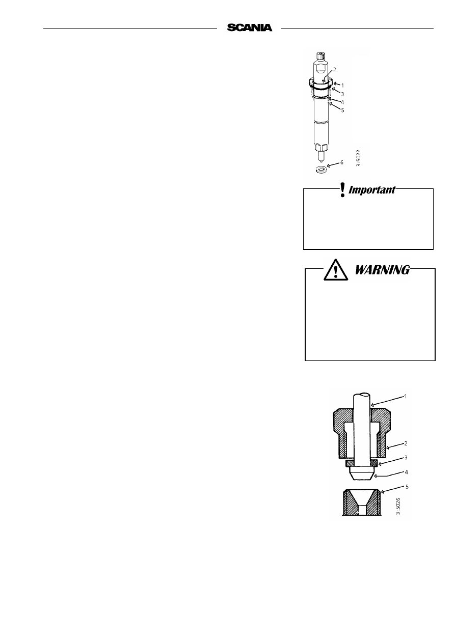
CHECKING THE INJECTORS

Injectors should be inspected by trained personnel with access to the neces-
sary equipment. Inspection should be carried out at least once a year or every 
2400 hours.

Removal

1.

Clean around the injectors and connections, including clamps and 
brackets.

2.

Detach the delivery pipe bundle and leak-off fuel lines.

3.

Unscrew the injector.

4.

Fit protective plugs on the injector and delivery pipe.

5.

Lift up the seal from the bottom of the injector seat if it does not come 
out together with the injector.

6.

Fit a core plug in the injector seat in the cylinder head.

7.

Clean the injectors and check/adjust in a nozzle tester.

Correct opening pressure, see Technical data, page 46.

Fitting

1.

Check that there is no old seal in place and fit a new seal in the bottom 
of the injector seat.

2.

Fit a new O-ring in the socket nut and a new seal under the socket nut.

3.

Fit the injector.

4.

Tighten the socket nut to 70 Nm (7.0 kpm).

5.

Fit the delivery pipe and tighten the union nuts to 20 Nm (2.0 kpm). Fit 
clamps and brackets.

Important

Take care to fit the delivery pipe without tension and make sure 
that the cone on it is correctly positioned in the connection. 

6.

Fit the leak-off fuel line. Tighten the bolts to 11 Nm (1.1 kpm).

1.

Delivery pipes 

2.

Cap nut 

3.

Washer 

4.

Cone 

5.

Connector on injector or 
injection pump

1.

Socket nut 

2.

O-ring 

3.

O-ring 

4.

Stop ring 

5.

Guide pin 

6.

Seal

The delivery pipes must

not be bent.

All clamps must be refitted.

Always wear gloves and eye 

protection when testing 

injectors.

Fuel escaping under high 

pressure can penetrate body 

tissue and cause serious injury.

34

2001-05:1

ELECTRICAL SYSTEM

15. Every 200 hours:

CHECKING THE ELECTROLYTE 
LEVEL IN BATTERIES

1.

Unscrew the plugs and check the electrolyte level in all cells.

2.

Top up with distilled water until the level is 10-15 mm above the plates.

16. Every 200 hours:

CHECKING THE STATE OF CHARGE IN 
BATTERIES

Note

Every 200 hours applies to generator sets and the like. Other 
installations every 1200 hours.

- Check the density with an acid tester.

In a fully-charged battery it should be:

1.280 at +20 °C

1.294 at 0°

1.308 at -20 °C

- If the density is below 1.20, the battery must be charged. A discharged 

battery freezes at -5 °C.

Do not rapid-charge the batteries. This will damage the battery in the
long run.

17. Every 200 hours:

CLEANING THE BATTERIES

Note:

Every 200 hours applies to generator sets and the like. Other 
installations every 1200 hours.

1.

Clean batteries, cables and cable terminals.

2.

Check that all cable terminals are firmly tightened.

3.

Grease battery terminal posts and cable terminals with vaseline.

Wear gloves and eye protection 

when charging and

handling batteries.

Batteries contain a highly 

corrosive acid.

Do not connect the cables to the 

wrong terminals.

This could cause serious 

damage to the electrical system.

If the terminals are

shortcircuited, sparks

will be generated. 

Do not let open flame or sparks 

come near the batteries.

When batteries are charged, 

they emit highly flammable 

fumes that can explode.

2001-05:1

18. Every 1200 hours:

CHECKING THE COOLANT LEVEL 
MONITOR

(optional equipment)

1.

Start the engine.

2.

Lower the coolant level in the expansion tank.

3.

Automatic stop in case of fault: The engine stops, the indicator lamp 
comes on and the buzzer sounds if the level monitor is OK. 

4.

Without automatic stop in case of fault: The indicator lamp comes on 
and the buzzer sounds if the level monitor is OK.

5.

Top up coolant to the correct level, refer to page 24.

2-pole level monitor installed 

in expansion tank for radiator 

supplied by Scania

Always use a suitable container 

to avoid spillage when

draining coolant.

Dispose of used coolant through 

an authorized waste disposal 

contractor.

36

2001-05:1

19. Every 1200 hours:

CHECKING THE TEMPERATURE 
MONITOR

1.

Drain the coolant, allowing the temperature monitor to be removed.

2.

Remove the temperature monitor cable(s).

3.

Unscrew the monitor.

4.

Refit the cable(s) to the monitor.

5.

Submerge the monitor sensor body in water. Heat the water slowly 
(approx. 1° minute) using e.g. an immersion heater.

6.

Set the control switch to "ON". Use a thermometer to check that the 
warning lamp comes on or that an alarm is initiated at the correct 
temperature.

The correct temperature is stamped on the hexagonal part of the 
monitor.

The monitor tolerance is 

±

3°.

CHECKING THE TEMPERATURE 
SENSOR

1.

Drain the coolant, allowing the temperature sensor to be removed.

2.

Remove the temperature sensor cable(s).

3.

Unscrew the sensor.

4.

Connect an ohmmeter to the temperature sensor.

5.

Submerge the sensor body in water. Heat the water slowly 
(approximately 1° per minute) using e.g. an immersion heater.

6.

Check the resistance at the temperatures given below.

7.

The sensor should give the following readings:

At temp. °C

Resistance 

Tolerance °C

60

134 

±

 13.5

±

4

90

51.2 

±

 4.3

±

3

100

38.5 

±

 3

±

3

2-pole temperature sensor 

C =Common connection 

1 =  Connection C -1 closes at 

stamped temperature 

2 = Connection C -2 opens at 

stamped temperature 

2-pole temperature monitor

Always use a suitable container 

to avoid spillage when

draining coolant.

Dispose of used coolant through 

an authorized waste disposal 

contractor.

2001-05:1

20. Every 1200 hours:

CHECKING THE OIL PRESSURE 
SENSOR/MONITOR

Sensor function

Measure the sensor output voltage (pin 3) at different oil pressures. The 
sensor output voltage shall be as follows:

0.85-1.15 bar = 2.45 volt
1.80-2.20 bar = 3.70 volt
2.75-3.25 bar = 4.50 volt
3.79-4.20 bar = 5.20 volt
4.55-5.45 bar = 5.70 volt
5.40-6.6 bar

= 6.10 volt

The tolerances apply at +30°C - 110°C. At lower temperatures the tolerance 
range is wider, e.g. 0°C = x 1.4.

Monitor function

Connect a test lamp to the oil pressure monitor, pin 4 (

-

 ground), and check 

that the monitor switches on at the correct pressure when the engine is started 
and stopped. The monitor shall switch on at 0.7 

±

 0.15 bar when the engine is 

stopped.

Important

The sensor/monitor must be supplied with voltage during the 
measurement. Maximum 4 W load from a test lamp.

Monitor connected for automatic stop in case of a fault: 

1.

Start the engine. 

1.

Check on the oil pressure gauge that oil pressure rises. 

2.

Stop the engine manually (using the emergency stop). 

3.

Check on the oil pressure gauge at what pressure the stop solenoid oper-
ates and the monitor opens. Correct pressure: 0.7 

±

 0.15 bar. 

Monitor connected to buzzer: 

1.

Main power switch in operating position, check that buzzer sounds. 

2.

With the engine running, check that the buzzer falls silent when the oil 
pressure is above 1.1 

±

0.15 bar and the monitor closes.

21. Every 400 hours:

CHECKING THE STOP FEATURE 

Check that the stop solenoid is activated and stops the engine when the stop 
signal is given by the button, temperature monitor, coolant level monitor and 
oil pressure monitor if these are coupled for automatic stop in the case of 
fault. 

Important

Stop solenoids with a timer module may be activated for start 
and stop a maximum of 3 times per minute. Otherwise, the 
timer module may be damaged and the stop feature cease.

4

1

3

2

38

2001-05:1

CHECKING STOP SOLENOID STOP POSITION

When changing the stop solenoid, or if the stop feature is not satisfactory, the 
following should be done (the figures show the stop control with the engine 
in stop position): 

Stop position at “Pull to stop”.

- Check and/or set the length of the link rod so that the distance between 

the locknuts (nut height 5.2 mm) is 21.0 

±


0.1 mm when the nuts are 

tightened. 

- Fit the stop solenoid in the bracket as in the figure. 

- Connect the stop solenoid electrically, red to battery 

+

 and black to

battery 

-

, and activate it so that it is fully pulled. 

Note:

 Pole reversal 

will damage the timer module

- Screw the clevis onto the stop lever using the link pin and check, in stop 

position, that there is a small clearance (0.2-0.3 mm) between the stop 
lever and the operating point on the governor 

- Check the stop feature by starting the engine and then stopping it by 

activating the stop solenoid. 

Important

The stop solenoid must not be activated more than 3 times per 
minute as the timer module can be damaged.

Installation “Pulled during

operation” 

Installation “Pull to stop” 

Stop position at “Pulled during operation”. 

- Check and/or set the length of the link rod so that the distance between 

the locknuts (nut height 5.2 mm) is 26.0 

±

0.1 mm when the nuts are 

tightened. 

- Fit the stop solenoid in the bracket as in the figure. 

- Connect the stop solenoid electrically, red to 

+

 and black to 

-

 and acti-

vate it so that it is fully pulled. Note: The timer module is damaged if 
the poles are reversed

- Turn the stop lever to operating position and screw the clevis onto the 

stop lever using the link pin and check, in operating position, that there 
is a small clearance (0.2-0.3 mm) between the stop lever and the operat-
ing point on the governor 

- Activete the stop solenoid and start the engine. Stop the engine by cut-

ting the power to the stop solenoid. 

Important

The stop solenoid must not be activated more than 3 times per 
minute as the timer module can be damaged.

2001-05:1

RENEWING THE BATTERY

Removal

1.

Disconnect the negative cable (-) from the battery (cable connected to 
ground).

2.

Disconnect the positive cable (+) from the battery (cable connected to 
starter motor).

Fitting

1.

Connect the positive cable (+) to the battery (cable connected to starter 
motor).

2.

Connect the negative cable (-) to the battery (cable connected to 
ground).

MISCELLANEOUS

22. Every 1200 hours:

CHECKING THE DRIVE BELT

Replace the drive belt (1) (poly V-belt) if worn or damaged.

Also check that the automatic belt tensioner (2) is working and keeps the 
drive belt correctly tensioned. 

1

2

Do not connect the cables to the 

wrong terminals.

This could cause serious 

damage to the electrical system.

If the terminals are short-

circuited, sparks will be 

generated. 

Dispose of used batteries 

through an authorized waste 

disposal contractor.

40

2001-05:1

23. Daily:

CHECKING FOR LEAKAGE, RECTIFY 
AS NECESSARY

- Start the engine.

- Check for oil, coolant, fuel, air and exhaust leakage.

- Tighten or change leaking connections. Check the overflow holes (1) 

which show whether the O rings between the cylinder liners and crank-
case are leaking, refer to illustration.

a) If coolant is leaking out, the two upper O-rings are leaking. 

b) If oil is leaking out, the lower O-ring is leaking.

A small amount of leakage from the overflow holes during the engine 
running-in period is normal. (Seals and O-rings to be lubricated with 
soap or oil when fitted).

This leakage normally stops after a time.

1

Ensure that any leakage does 

not pollute the environment. 

In case of major leakage, 

contact the nearest Scania 

workshop.

2001-05:1

24. Every 2400 hours:

CHECKING/ADJUSTING VALVE 
CLEARANCE

Note

Checking/adjusting valve clearance should also be done after the 
first 400 hours of operation.

Valve clearances should be adjusted when the engine is cold, at least 30 min-
utes after running.

The rocker cover gaskets should be changed as necessary. Tightening torque: 
20 Nm.

Intake valve clearance: 0,45 mm.
Outlet valve clearance: 0,80 mm.

Alternative 1

- Set No. 1 cylinder to TDC by turning the engine in its direction of rota-

tion until both valves are closed. 

- Adjust the following valves. Correct valve clearance is indicated on the 

instruction plate on one of the rocker covers:

- Set No. 6 cylinder to TDC by turning the engine one revolution in its 

direction of rotation and adjust the following valves:

Cylinder 

1

Intake and exhaust

2

In

3

Ex

4

In

5

Ex

Cylinder 2

Ex

3

In

4

Ex

5

In

6

In and Ex

Covers for reading 

on flywheel casing

Note 

Readings can either be taken 

from underneath or from 
above, depending on which 
flywheel is used. 

The cover not being used is 

covered with a seal and an 
instruction plate.

TDC 

No. 6 cyl

TDC 

No. 1 cyl 

Intake valve

Exhaust valve

5

4

3

2

1

6

Cylinder numbering

FLYWHEEL

FLYWHEEL

WARNING

Immobilise the starting device 

when working on the engine.

If the engine starts out of 

control, there is a

SERIOUS RISK 

OF INJURY.

42

2001-05:1

Alternative 2 

- Set the No. 1 cylinder to TDC by turning the engine in its direction of 

rotation until both valves are closed. 

- Adjust both the valves for the No.1 cylinder. Correct valve clearance is 

indicated on the instruction plate on one of the rocker covers.

- Repeat this procedure with the remaining cylinders in the order 

5 - 3 - 6 - 2 - 4 (firing sequence) by turning the engine 1/3 revolution in 
its direction of rotation between each adjustment.

25. Every 2400 hours:

CHANGING (or CLEANING) THE 
CLOSED CRANKCASE VENTILATION 
VALVE

Alternative 1:

Change the valve at the specified interval.

Alternative 2:

- Remove the valve after the specified interval.

- Clean the valve by placing it in a bath of diesel oil overnight. Then rinse 

it several times in diesel oil and allow it to drip dry.

- Refit the valve.

- The valve may be reused (cleaned), maximum twice after the initial 

2400 hours of operation. Take care to mark the valve after cleaning it.

2001-05:1

LONG-TERM STORAGE

If the engine is not to be used for a lengthy period of time, special measures 
should be taken to protect the cooling system, fuel system and combustion 
chamber from corrosion and the exterior from rusting.

The engine can normally stand idle for up to six months. If it remains unused 
for longer than this the following measures, which provide protection for 
about four years, should be adopted. An alternative to preparing the engine 
for long-term storage is to start the engine and warm it up every 6 months.

Preparing the engine for long-term storage means:

- Thoroughly cleaning the engine

- To run the engine for a period of time with preservative fuel, 

preservative oil and preservative coolant.

- Otherwise preparing the engine for storage (filter changes, lubrication, 

etc.).

Preservative coolant

If the engine is to be stored with a full cooling system, use coolant containing 
50% glycol by volume. Glycol without nitrite-based inhibitor must be used.
E.g. BASF G48 or BASF D542.

Preservative fuel

- Use diesel fuel mixed with Lubrizol 560A or equal.

- Mix  1  cm

3

 (ml) of Lubrizol 560A with 10 dm

3

 (l) of fuel.

HANDLING LUBRIZOL 560A

Hazardous!

Contains aromatic hydrocarbons

Use spot extractors where there is a danger of vapour build-up.

Wear protective gloves and goggles when handling Lubrizol. Do not use contaminated clothing.

In case of splashes in the eye: Rinse with moderate water spray (for min. 15 minutes). Seek medical attention.

In case of skin contact:

Wash affected areas with soap and water.

If you inhale it:

Fresh air, rest and warmth

Flammable:

Fire class 2A. Flash point + 27°.
In case of fire: Extinguish using carbonic acid, powder or foam

Storage:

In properly sealed container in a dry, cool place. Keep out of reach of children.

!

Ethylene glycol, if swallowed 

can be fatal.

Avoid contact with the skin.

44

2001-05:1

Preservative oil

Suitable preservative oil can be supplied by most petroleum companies.

E.g. Dinitrol 40 or the equivalent.

Preparations for storage

- Drain and flush the cooling system. Top up with preservative coolant.

- Warm up the engine on regular fuel. Stop the engine and drain the oil.

- Change the fuel filter and turbo filter.

- Fill the engine with preservative oil up to the minimum level on the 

dipstick.

- Mix preservative fuel in a can. Detach the fuel pipe at the feed pump 

suction line and connect a hose from the can.

- Detach the fuel pipe at the overflow valve and connect a return hose to 

the can.

- Start the engine and run it at approximately 1000 rpm (not single-speed 

engines) for 20-25 minutes.

- Stop the engine, remove the hoses and connect the normal fuel lines.

- Oil the valve mechanism generously with preservative oil.

- Remove the injectors and spray preservative oil into each cylinder, 

maximum 30 cm

3

 (ml).

Turn the engine over a few revolutions using the starter motor. Spray an 
additional small amount of oil into each cylinder.
After this the engine must not be cranked. Refit the injectors.

- Drain the preservative oil from the engine. Fresh engine oil can be filled 

directly or when the engine is taken out of storage.

- Drain the coolant if the engine is not to be stored with a full cooling 

system. Plug and tape over all coolant connections (if the cooling system 
is not completely assembled).

- Air cleaner: Clean or renew the filter element.

- Cover air intakes and exhaust pipes.

- Alternator and starter motor:

- Spray with water-repellent anti-corrosive oil, CRC 226, LPS1 or equal.

- Spray the outside of bright metal engine parts, first with penetrating pre-

servative oil such as Dinitrol 25B and then with Dinitrol 112 or equal.

Always use suitable containers 

to avoid spillage when

draining oil and coolant.

Dispose of used oil and coolant 

through an authorized waste 

disposal contractor.

2001-05:1

- Attach a label to the engine showing the date of preservation and 

clearly stating that it must not be started or cranked.

Batteries

Remove the batteries for trickle charging at a charging station. (Does not 
apply to batteries, which the manufacturer specifies to be maintenance free). 
The same is applicable for short-term storage if the engine has not been 
prepared for storage as above.

Storage 

After the preparations, the engine should be stored in a dry and warm place 
(room temperature).

Taking out of storage

(Procedure when the engine is to be put into operation)

- Remove plugs and tape from coolant connections, air intakes and 

exhaust pipes.

- Fill the cooling system with coolant, refer to page 12.

- Check the oil level in the engine or fill up with fresh motor oil.

- Turn the engine over a few times with the injectors removed, at the same 

time copiously oiling the valve mechanism with pushrods and tappets.

Important

The engine must be cranked with the injectors removed so that 
surplus preservative oil will be pressed out of the cylinders.

- Fit the injectors.

- Empty the fuel system’s main filter of preservative oil.

- Bleed the fuel system.

- Wash off any externally applied preservative oil, using white spirit.

STORED ENGINE

Date . . . . . . . . . . .

Do not start or crank!

Wear gloves and eye protection 

when charging and handling 

batteries.

Batteries contain a highly 

corrosive acid.

46

2001-05:1

TECHNICAL DATA 

GENERAL D9

DI9

DC9

Number of cylinders 

6 in line 

Cylinder bore

mm

115

Stroke

mm

144

Displacement

dm

3

 (litres)

9,0

Number of main bearings 

7

Firing sequence 

1 - 5 - 3 - 6 - 2 - 4

Compression ratio 

17:1

Engine direction of rotation viewed from rear 

Anti-clockwise 

Fan direction of rotation viewed from the front 

Clockwise 

Cooling 

Fluid 

Valve clearance, cold engine

 intake valve

mm

 exhaust valve

mm 

0,45

0,80

Weight, without coolant and oil
*With charge air cooler, radiator, 

kg

expansion tank and pipes 

825

835

890*

Output 

see “Engine record card”     

LUBRICATION SYSTEM 

Max. oil pressure

 (warm engine at speed above 800 rpm) bar (kp/cm

2

)

6

Normal oil pressure

 (warm engine at operating speed)

bar (kp/cm

2

)

3 - 6

Min. oil pressure

 (warm engine 800 rpm) 

bar (kp/cm

2

)

0,7

Oil capacity, see page 21 

Crankcase pressure with closed crankcase

mm VP

ventilation

-55 - +20 

2001-05:1

FUEL SYSTEM 

D9

DI9

DC9

Pump setting BTDC 

See plate on rocker cover 

Injectors, opening pressure

bar (kp/cm

2

300

Low idle

rpm

700

Maximum full load speed 

See engine card 

Fuel 

Diesel fuel oil

Tightening torques:

 Socket nut for injectors

Nm

 Cap nut for delivery pipe

Nm

 Oil leakage connection

Nm 

70

20

11

1

 see page 48 

COOLING SYSTEM 

Number of thermostats 

1

Thermostat, opening temperature

°

C    

79

Coolant temperature:

 system with atmospheric pressure

°

C

 system with positive pressure

°

C    

70 - 93

70 - about 100

Capacity including 0.75 m

2

 radiator and 

expansion tank

dm

3

 (litres) 

50

53

50

ELECTRICAL SYSTEM 

System voltage

24

Alternator, current

65 alt. 90

Starter  motor  power

kW (hp)    

4,0 (5,4)

Monitors, settings:

 Oil pressure monitor

bar (kp/cm

2

)

  Temperature  monitor

°C    

<

2-pole:1.0

±


0.15 

Stamped on monitor hexagon 

48

2001-05:1

FUEL

Diesel fuel

The composition of the diesel fuel is vitally important to the operation and 
life of the engine and the fuel injection pump. The engine power output and 
the exhaust emissions are also dependent on the fuel quality.  The 
requirements and the test standards for the most important properties are 
described in the workshop manual in sections that can be ordered from your 
Scania dealer or directly from Scania. The address of Scania is printed on the 
cover.

The diesel fuel shall comply with the following standard: EN 590 (European 
standard).

The table below shows the requirements for some of the most important 
properties:

Environmentally favourable fuels (low sulphur fuels)

There are three different grades of so called environmentally favorable fuels 
(SS15 54 35). Grade 1 is sulphur-free and grade 2 is low in sulphur. 
Compared with class 3 (normal fuel), these fuels are less dense and this 
reduces engine power output. Only class 1 fuel should be used with a 
catalytic converter.

Short term use of fuel with a higher sulphur content than 0.05% by weight 
will not cause permanent damage to the catalytic converter.

The catalytic converter may, however, require fuel with low sulphur content 
for some time after this to regain its normal efficiency.

Property

Requirement

Viscosity at 40

°

C

2.0 - 4.5 mm

2

/s (cSt)

Density at 15

°

0.82 - 0.86 kg/dm

3

Sulphur (concentration by mass)

max. 0.3%

Ignitability (CET rating)

min. 49

Flashpoint

56°C

2001-05:1

Temperature dependence of diesel fuel

At temperatures lower than those specified for the diesel fuel, paraffin wax 
may precipitate from the fuel and block filters and pipes. The engine can then 
loose power or stop.

The diesel fuel is adapted for use in the specific climate of each country. If a 
vehicle or an engine is to be operated in a temperature zone with lower 
temperature than normal, first identify the temperature properties of the 
fuel concerned
.

The properties of the fuel when cold can be improved by adopting one of the 
following measures before the temperature drops:

- If the fuel concerned is not intended for the expected temperature and no 

diesel fuel with the correct temperature properties is available, we 
recommend that an electric fuel heater be installed as a preventative 
measure.

- The low temperature properties of diesel fuel may be improved by 

adding kerosene as a preventative measure. A maximum of 20% may 
be added. When refuelling, the kerosene should be added first, so that it 
mixes thoroughly with the diesel fuel.

Note:

It is prohibited to use kerosene in engine fuel in some countries.

- To prevent water in the fuel from freezing and forming ice, maximum 

0.5-2% alcohol (isopropanol) may be added. 

Drain fuel tanks and drain or renew fuel filters at regular intervals.

It is not permitted to mix 

kerosene with diesel fuel that is 

already adapted for the climate 

concerned. The injection pump 

may be damaged. All use of 

paraffin other than kerosene is 

forbidden, as it causes engine 

damage.

It is not permissible to mix 

petrol with diesel fuel. Petrol 

may cause wear to the fuel 

injection pump and it may also 

cause damage to the engine.


Content      ..     1      2      3