SCANIA INDUSTRIAL ENGINES (specification) - part 30
SCANIA industrial engines
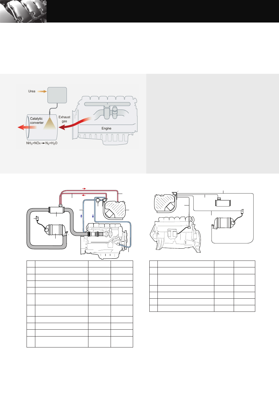
sCr system
us tier 4i, eu stage iiiB
SCR (Selective Catalytic Reduction) technology is used on Scania’s engines
for Stage IIIB and Tier 4i to reduce the NO
X
content in the exhaust gases.
A chemical process is started by injecting reductant, a urea and water
mixture, into the exhaust gas stream. During injection the water evaporates
and the urea breaks down to form ammonia. The ammonia then reacts
with the nitrogen gases in the catalytic converter and forms harmless
products such as nitrogen gas and water. Through the use of SCR the
exhaust gases are purged of poisonous levels of NO
X
in the best possible
way. Scania is making use of a system that is carefully developed and
tested in our own laboratory.
The reductant tank holds 38 or 60 litres and is heated by the engine’s
cooling system in order to avoid freezing of the urea solution, urea
freezes at -11°C. The reductant tank and a pump module are delivered
as a unit which is fi tted to brackets for an easy installation. The Scania
system contains all mechanical and electrical parts needed except from
the exhaust piping which is to be adapted according to the customers
installation.
Mechanical system
Standard
Optional
1
Reductant tank and pump module
38 l
60 l
2
Reductant fl uid return line
2 m
3.5 m
3
Coolant valve
–
4
Reductant pressure line
2 m
3.5 m
5
Coolant hose for tank and pump
heating
–
–
6
Evaporator module / Hydrolysis
catalyst with reductant doser
–
7
NO
X
sensor with control unit
–
8
SCR catalyst
–
9
Temperature sensor
–
10
Coolant hose, return from tank and
pump heating
–
–
Mechanical system
Electric system
Electric system
Standard
Optional
1
Customer interface, SCR system
–
2
Pipe network between engine and
SCR control unit
3 m
6 m
3
Electrical interface, SCR system
–
4
Temperature sensor electrical cable
3 m
6 m, 9 m
5
Reductant doser electrical cable
3 m
6 m
6
NO
X
sensor electrical cable
3 m
6 m
The principle for Scania SCR system
This specifi cation may be revised without notice.
6
1
9
2
8
3
7
5
10
4
1:7058
3
1
2
6
5
4
1:7059