содержание .. 10 11 12 13 ..
Scania 16 litre engine. Work Description - part 12
0101w14b.mkr
©
45
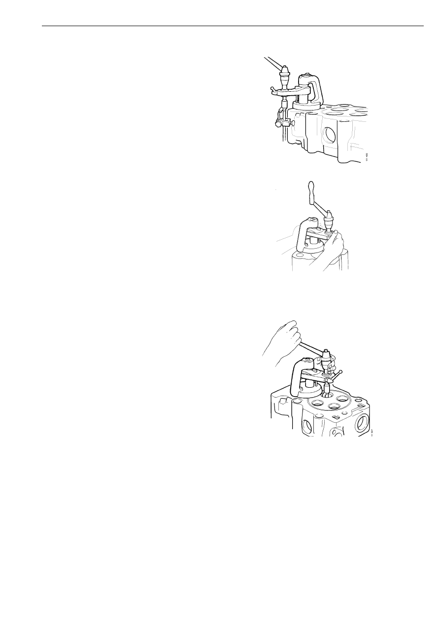
5
Set up the dial on the cutter adjuster using a
valve.
6
Adjust the cutter. Diameter 37.9 mm and
39.8 mm respectively, refer to Valve seat
insert, machining measurement.
7
Turn off the magnet (position 2). Insert the
guide spindle into the valve bushing. Adjust
the pivot plate so that the distance between
the cutter and the valve seat is
approximately 1 mm. Centre the tool
precisely.
01_1233
8
Turn on the magnet (position 1).
9
Apply the quick-action lock. Make sure the
crank can be turned easily. If not, redo the
centering.
10 Machine the valve seat by cranking
clockwise while turning the feed screw.
Never crank counterclockwise as this will
damage the cutter. Lubricate with cutting oil
while machining.
11 When the surface of the valve seat has been
machined, reduce the cutting pressure by
turning 2-3 revolutions without any feed.
Continue turning while backing the feed
screw. The valve seat cutter is now ready for
the next valve seat.
The valve seats can also be machined using tool
587 061.
Cylinder head