Scania 16 litre engine. Work Description - part 8


  Главная      Scania     Scania 16 litre engine - Work Description


поиск по сайту            


содержание   ..  6  7  8  9   ..


Scania 16 litre engine. Work Description - part 8


0101w14b.mkr

©

29

14 Remove the bearing bracket.

15 Remove the pushrods.

Note: The pushrod for the unit injector is 
secured with a retaining ring. Jiggle and pull 
carefully on the pushrod to loosen it.

16 Remove the valve yokes.

17 Disconnect the cables on the unit injector 

and pull them out through the opening in the 
rocker cover.

18 Remove the lower rocker cover.

19 Remove the screw for the fork clamp 

holding the unit injector in place.

Note: Do not lift the unit injector by its spring, 
the spring can come loose.

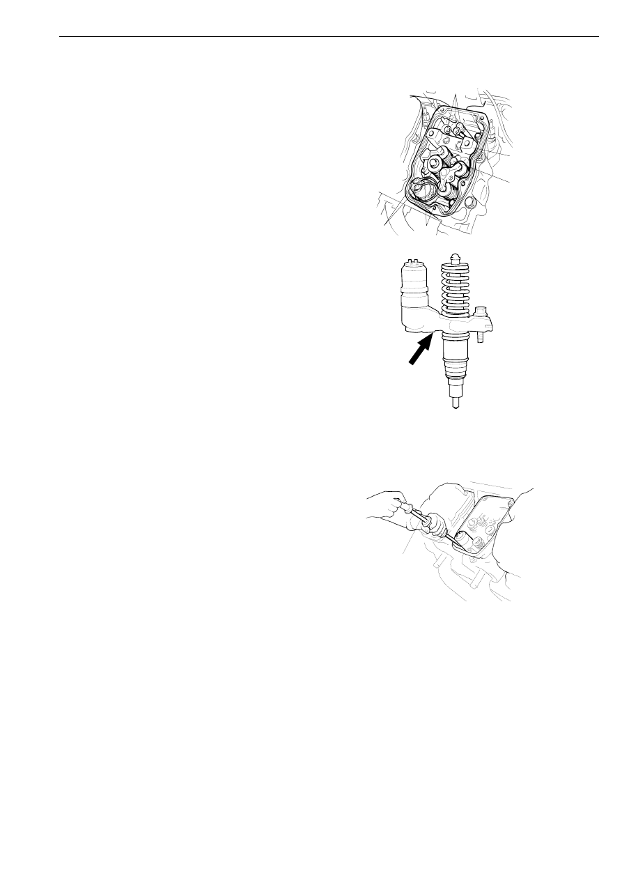
20 Turn the unit injectors clockwise until they 

stop. Place the slide hammer 87 596 
between the solenoid valve and the edge of 
the lower rocker cover as illustrated.

114 728

17

14

18

15

16

19

Place the slide hammer as indicated by the 
arrow

116 271

111 685

87 596

21 Pull out the unit injector. If the unit injector 

is stuck, tap carefully with a rubber mallet 
on the solenoid valve housing.

22 Remove the cylinder head. Mark the 

cylinder heads if more than one is being 
removed at the same time.

Cylinder head

30

©

0101w14b.mkr

Fitting

Tightening torques

Special tools

Cylinder head bolts

First stage

60 Nm

Second stage

150 Nm

Third stage

250 Nm

Fourth stage

90

°

Screws for lower rocker cover

26 Nm

Bolt for fork on unit injector.

20 Nm + 75

°

Bearing bracket and rocker arm shaft

105 Nm

Screw for upper rocker cover

18 Nm

Adjusting screw lock nut on rocker arm for unit injector

39 Nm

Adjusting screw lock nut on rocker arm for valves

35 Nm

Cable connection, unit injector

2 +/- 0,2 Nm

Bolt for exhaust manifold

63 Nm

Screw for fuel manifold

26 Nm

Banjo screw for overflow line

11 Nm

Number

Designation

Illustration

Tool board

99 308

Sleeve

D 5

99 365

Setting tool

Measuring tool cabinet

588 179

Torque screwdriver

99 365

C

112 104

588 179

Cylinder head

0101w14b.mkr

©

31

1

Check liner height, refer to section on 
pistons and cylinder liners.

2

Fit a new cylinder head gasket.

3

The cylinder head bolts can be reused up to 
3 times. Therefore, make sure the bolts have 
no more than 2 punch marks on top of the 
bolt head. If any of the bolts has 3 marks, it 
must be replaced with a new one.

4

Lubricate the threads and underneath the 
heads of the cylinder head bolts. Tighten 
them in the following four stages in the 
order given in the figure.

Torque tighten all bolts to 60 Nm.

Torque tighten all bolts to 150 Nm.

Torque tighten all bolts to 250 Nm.

Finally, tighten all bolts an 
additional 90

°.

Make a mark with a centre punch on the 
head of the bolt.

5

Fit the lower part of the rocker cover and 
torque tighten the screws to 26 Nm.

1

2

3

4

5

6

01_1396

Cylinder head

32

©

0101w14b.mkr

6

Make sure there is not an old seal at the 
bottom of the injector aperture. Clean the 
sealing surfaces in the injector aperture.

IMPORTANT! Always fit new O-rings and 
seals to unit injectors that have been removed. 
Make sure all sealing surfaces are clean.

107 512

7

Lubricate the unit injector O-rings with red 
O-ring grease, part No. 1 402 039.

8

Fit a new seal on the unit injector. A rubber 
insert will keep the seal in place on the unit 
injector.

9

Place the fork clamp with screw in position 
on the unit injector and insert it into the 
cylinder head. Press down the unit injector 
by hand as far as possible.

107 513

10 Torque tighten the screw to 20 Nm and then 

a further 75°. There are two marks in the 
rocker cover with a 75° angle between them.

A

B

75

o

116 559

Cylinder head


содержание   ..  6  7  8  9   ..