SAAB 9000. Manual - part 55
12•12 Body electrical systems
Removal
4 Disconnect the battery negative cable, and
position it away from the terminal.
5 Refer to the relevant paragraphs of Chap-
ter 11, Section 27, and remove the panel from
the top of the facia.
6 With reference to Chapter 3, remove the air
ducting from above the instrument panel.
7 Apply light hand pressure at the rear of the
module, to release it from the facia.
8 At the rear of the module, disconnect the
multi-plug cable connectors, labelling the,m to
aid refitting later.
Refitting
9 Refit the clock/trip computer module by
reversing the removal procedure. Ensure that
the multi-plug cable connectors are refitted
according to the notes made during removal,
and that they are firmly plugged in.
Removal
1 Disconnect the battery negative cable, and
position it away from the terminal.
2 Refer to the relevant paragraphs of Chap-
ter 11, Section 27, and remove the ashtray
assembly from the facia front panel.
3 Unplug the cable connectors from the rear
of the cigarette lighter body, labelling them to
aid refitting later.
4 Using a small, flat-bladed screwdriver, prise
off the metal retaining clip, then withdraw the
cigarette lighter from the ashtray.
Refitting
5 Refit the cigarette lighter by reversing the
removal procedure.
General
1 Two types of speedometer drive
mechanism have been fitted. Vehicles built
before 1987 have a conventional speedometer
cable, which drives the speedometer remotely,
by means of a cable with a rotating, flexible
inner shaft.
2 An erratic or inconsistent speedometer
display, such as needle flickering or jumping,
may be attributable to wear in the
speedometer drive cable.
3 Vehicles built after 1987 are fitted with an
electronic transducer in place of the drivegear.
This device measures the rotational speed of
the transmission final drive, and converts the
information into an electronic signal, which is
then sent to the speedometer module in the
instrument panel. The signal is also used as an
input by the engine management system ECU
(and where fitted, the cruise control ECU, the
trip computer, and the traction control system
ECU).
Removal
4 Refer to the relevant paragraphs of Chap-
ter 11, Section 27, and remove the panel from
the top of the facia.
5 With reference to Chapter 3, remove the air
ducting from above the instrument panel.
6 Disconnect the drive cable from the rear of
the speedometer module.
7 Release the cable from the clips securing it
to the inside of the facia, then pull the free end
of cable through the bulkhead into the engine
bay, noting the cable routing. Do not use
excessive force, as this may damage the
rubber grommet at the bulkhead.
8 At the gearbox, unscrew the knurled nut at
the point where the speedometer cable enters
the differential casing. Withdraw the cable
inner from the drivegear.
9 Remove the speedometer cable from the
vehicle.
Refitting
10 Refit the speedometer drive cable by
reversing the removal process. Follow the
same routing behind the facia as the original
drive cable, ensuring that all moving
components are avoided. Do not force the
cable to follow tight curves, as this may
adversely affect the rotation of the cable inner.
Horn push buttons
1 Disconnect the battery negative cable, and
position it away from the terminal.
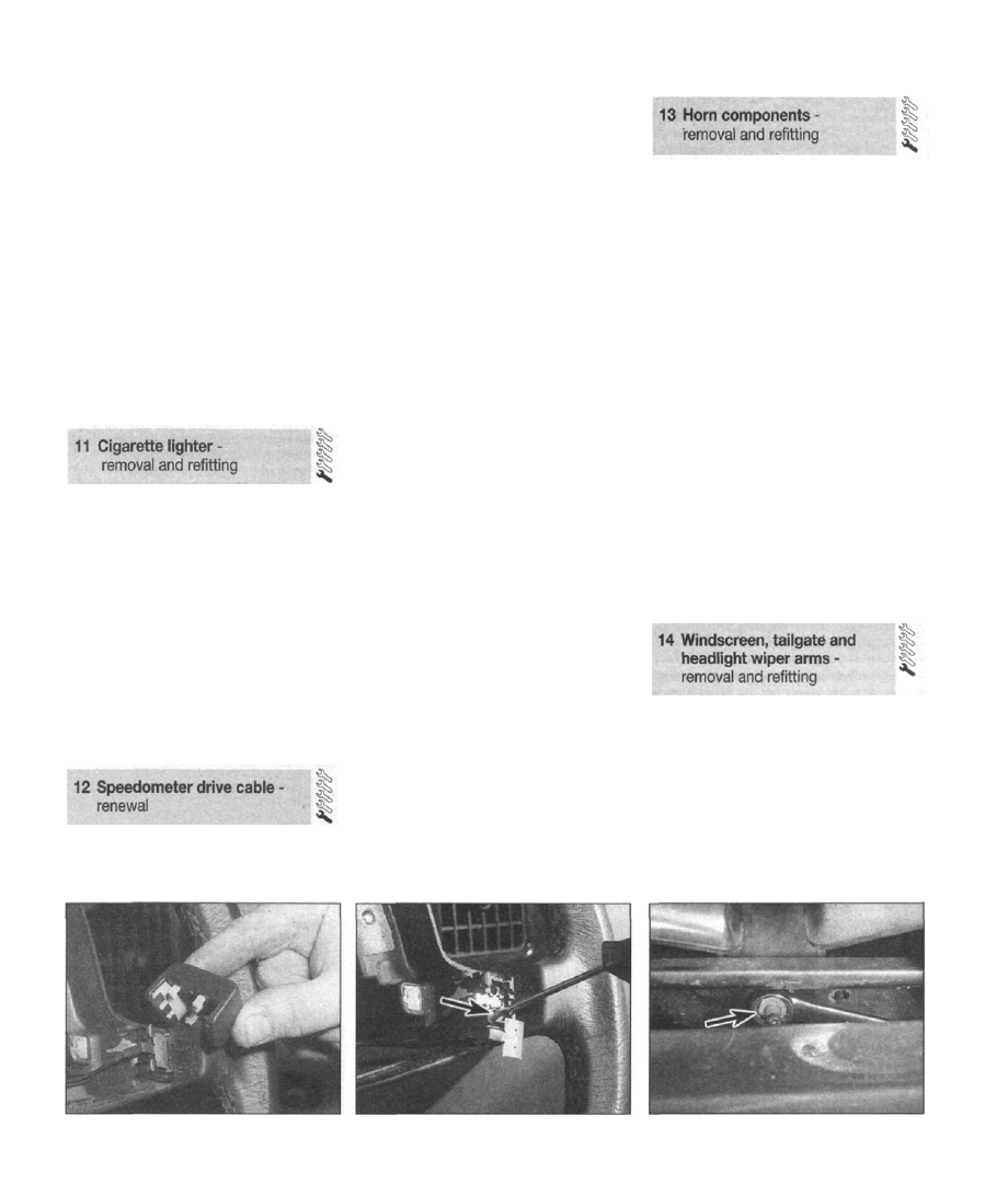
2 Using a thin plastic spatula, prise the horn
button from the steering wheel spoke, and lift
off the upper electrical contact (see
illustration).
3 Remove the retaining screw, and lift off the
lower electrical contact (see illustration).
4 Examine both the lower and upper contacts
for signs of wear or corrosion; renew them if
necessary.
5 Refitting is a reversal of removal.
Horns
Note: On early models, the second horn is
mounted in the engine bay, inside the left-
hand wheelarch.
6 Disconnect the battery negative cable, and
position it away from the terminal.
7 Refer to Chapter 11, Section 8 and remove
the front grille.
8 Unplug the wiring harness connector from
the horn.
9 Slacken and withdraw the retaining nut at
the bottom of the horn bracket, and lift off the
horns (see illustration).
Windscreen wiper arms
1 Note the position on the windscreen at
which wiper blades settle, when in the parked
position. Mark this position on the screen with
a strip of masking tape.
2 Flip up the hinged plastic cover at the base
of the wiper arm, to expose the retaining nut.
3 Slacken and remove the nut, then lift off the
wiper arm.
4 When refitting, ensure that the splined drive
spindle engages with the wiper arm mounting
13.2 Prise the horn button from the
steering wheel spoke (airbag removed for
clarity)
13.3 Remove the retaining screw, and lift
off the lower electrical contact (airbag
removed for clarity)
13.9 Slacken and withdraw the retaining
nut (arrowed) at the bottom of the horn
bracket