SAAB 9000. Manual - part 48


  Index      Saab     SAAB 9000 4-cyl 1985 to 1998 (C to S registration) - Service and Repair Manual


Search            copyright infringement  


Content   ..  46  47  48  49   ..


SAAB 9000. Manual - part 48


11 •8 Bodywork and fittings

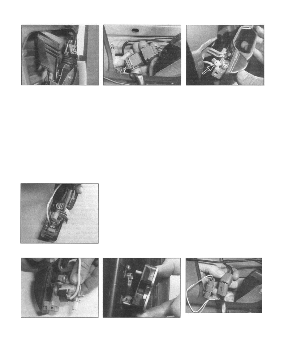
13.10a Remove the window glass guide

channel

locking switch cable from the guide channel
as it is withdrawn from the inside the door, and
unplug it from the wiring harness at the
connector (see illustrations).
11
 Lift the handle assembly away from the
door, together with the rubber seal. Guide out

the internal components carefully, to avoid
scratching the paintwork.

12 A link rod connects the lock cylinder to the
internal lock mechanism by means of plastic
balljoints; use a screwdriver to separate the
balljoint at the lock cylinder (see illustration).

Refitting

13 Offer up the handle assembly to the door

aperture, ensuring that the rubber seal is
correctly seated.

13.20a Remove the lock cylinder retaining

screws..

13.10b Unplug the central locking switch

cable from the wiring harness at the

connector

14 Snap the link rod balljoint back onto the
lock cylinder. Ensure at this point that the
roller protruding from the back of the handle
engages with the internal lock mechanism
release lever
15 Refit the handle retaining screws. Operate

the door handle to check that the door release
functions correctly, before progressing any
further.
16 Press the central locking switch cable into
the clip at the top of the window glass guide
channel, then bolt the strip in position inside
the door, whilst pulling the slack in the cable
through at the same time. Push the remainder
of the cable into the clips on the guide
channel, then plug together the harness
connector.
17 Refer to Section 12 and refit the door
interior trim panel.
18 Reconnect the battery negative cable, and

test the operation of the electric window. If the
window glass sticks, or is abnormally slow in

its movement, slacken the guide channel
screws at the edge of the door, to allow it
adopt the correct position in relation to the
window glass, then retighten the screws.

Lock cylinders

19 Remove the front door exterior handle, as
described earlier in this Section.

20 The lock cylinder is secured to the handle
assembly by two screws; remove these and
withdraw the cylinder, recovering the sealing
washer if it is loose (see illustrations).

13.12 Separate the link rod balljoint at the

lock cylinder (arrowed)

21 When refitting the cylinder, ensure that the
sealing washer is correctly seated before re-
tightening the retaining screws.

Lock mechanism

Note: This procedure is applicable to both the
front and rear door lock mechanisms, with the

exception that references to the lock cylinder
should be ignored when dealing with the rear
door lock mechanism.

Removal

22 The door lock mechanism is made up of
two assemblies; one bolted externally on the
rear edge of the door, containing the latch
components, and one bolted inside the door
void, housing the central locking servo and
release mechanisms.
23 To remove the external assembly, open
the door and remove the three screws that
secure the assembly to the door (see
illustration).
 Note that additional location is
provided by two dowels.
24 Ensure that the window glass is fully
raised. Disconnect the battery negative cable,
and position it away from the terminal.
25 Refer to Section 12 and remove the door
interior trim panel.
26 Unplug the cables leading to the central
locking servo and "door open" switch at the
connectors; label them to aid refitting later
(see illustration).
27
 Unbolt the window glass guide channel,
and after unclipping the central locking cable,

13.20b  . . . and withdraw the cylinder,

recovering the sealing washer if it is loose

13.23 Removing the external door lock

assembly

13.26 Unplug the cables leading to the
central locking servo and "door open"

switch at the connectors

Bodywork and fittings 11 •9

13.30a Remove the two screws that retain

the internal lock mechanism assembly,

located on the rear edge of the door...

withdraw the guide channel from inside the
door (refer to illustration 13.10).
28 The lock cylinder actuates the lock
mechanism via a link rod, secured by plastic
balljoints at each end. Use a screwdriver to
separate the balljoint at the lock mechanism
(refer to illustration 13.12).
29 At the door latch release lever on the lock
mechanism, unhook the link rod that runs to
the interior door handle.
30 Remove the two screws that retain the
internal lock mechanism assembly, located on
the rear edge of the door and at the lower
edge of the door, adjacent to the central
locking servo (see illustrations).
31 Withdraw the lock assembly from the
door, together with the link rod connected to
the internal lock release knob.

Refitting

32 Offer up the lock mechanism to its
mounting position inside the door, and refit the
retaining screws. Ensure at this point that the
lock mechanism release lever engages with
the tab protruding from the back of the
exterior door handle.
33 Attach the interior door handle link rod to
the latch release lever on the lock mechanism.
34 Snap the lock cylinder linkage balljoint into
place at the lock release lever.
35 Refit the window glass guide channel,
feeding the central locking cable through the
clips as the channel is fitted. Insert and tighten
the retaining screws.
36 Plug together the connectors for the
central locking servo and "door open" switch
cables.
37 Operate the handle a couple of times to
check that the exterior door release is
functioning correctly, before progressing any
further.
38 Fit the external lock mechanism into place,
engaging the locating dowels with the
corresponding holes. Refit and tighten the
three retaining screws.
39 Refer to Section 12 and refit the door

interior trim panel.

40 Reconnect the battery negative cable, and
test the operation of the electric windows. If
the glass sticks, or is abnormally slow in its

movement, slacken the guide channel screws

13.30b  . . . and at the lower edge of the

door, adjacent to the central locking servo

at the edge of the door, to allow it adopt the
correct position in relation to the window
glass, then retighten the screws.

Striker plate

41 The striker plate posts are screwed into
the B/C-pillars, and can removed using a
spanner on the hex bolt heads at the base.

Warning: If a glass panel is being

removed to due to breakage,
carefully dislodge all loose
fragments of glass from the panel

before attempting to remove it. Protect

your eyes and hands with suitable goggles

and gloves, and dispose of the glass
safely, labelling any packages containing
broken glass to warn others of the
contents. Remember to remove any
fragments of glass that may have dropped
down inside the door panel.

Front door window glass

Removal

1 Lower the window glass by approximately

three-quarters of its travel.
2 Disconnect the battery negative cable, and

position it away from the terminal.

14.4 Carefully prise the rubber sealing strip

from the outside edge of the window

aperture

3 Refer to Section 12 and remove the door

interior trim panel.

4 Carefully prise the rubber sealing strip from
the outside edge of the window aperture (see
illustration); if an implement is used as a
lever, select one that will not scratch the
paintwork. The rubber sealing strip has a
mounting channel that contains a flexible
metal core; avoid splaying out the sides of the
channel excessively during removal, as a good
seal will be hard to attain on refitting.
5 Working inside the door at the lower edge of
the window glass, use a pen to mark the
relationship between the window regulator
bracket and the window glass support frame.
6 Remove the two flange screws that secure
the glass in place; support the glass as the last
screw is removed, to prevent it from dropping
down inside the door (see illustration).

Roll up a dust sheet and lay it
inside the door, underneath
the lower edge of the window
glass. This will support the

glass as it is released, and provide
cushioning if it is accidentally dropped
during the removal process.

7 Push the glass up through the door, and lift
it clear of the vehicle (see illustration). Set it
down on padded surface, to prevent the
edges from chipping.

14.6 Remove the two flange screws

(arrowed) that secure the glass in place

14.7 Push the glass up through the door,

and lift it clear of the vehicle

11•10 Bodywork and fittings

14.18 Free the window channel upright

from the (rear) door frame by removing the
retaining screw from the inside edge of the

door panel (arrowed)

Refitting

8 Lower the glass into the door, and align the
frame mounting holes with those on the
window regulator bracket. Refit the retaining
flange screws, using the marks made during

removal to achieve the correct alignment
before tightening them; this should avoid the
need to adjust the window after refitting.

9 Press the rubber sealing strip back onto the
edge of the window aperture, ensure that it is
level and secure.

10 Reconnect the battery negative cable, and

test the operation of the electric window. If the
window glass is not correctly aligned in the
aperture, particularly in the closed position,
slacken the window glass-to-regulator bracket
screws, and manoeuvre the glass manually to
achieve the desired fit, then retighten the
screws. In addition, if the glass sticks or is
abnormally slow in its movement, slacken the
guide channel screws at the edge of the door,
to allow it adopt the correct position in relation
to the window glass, then retighten the
screws.
11 Refit the door interior trim panel, referring
to Section 12 for details.

Rear door window glass

Removal

12 Lower the window glass by approximately

three-quarters of its travel.

13 Disconnect the battery negative cable,

and position it away from the terminal.

14 Refer to Section 12 and remove the door
interior trim panel.
15 Carefully prise the rubber sealing strip

from the inside edge of the window aperture; if
an implement is used as a lever, select one
that will not scratch the paintwork. The rubber
sealing strip has a mounting channel that
contains a flexible metal core; avoid splaying
out the sides of the channel excessively during
removal, as a good seal will be hard to attain
on refitting.
16 Carefully prise off the plastic moulding
from the outside lower edge of the window
aperture.

14.29 Unplug the window regulator motor

from the wiring harness at the connector

17 Pull the rubber sealing strip from the
window channel upright.
18 Free the window channel upright from the
door frame by removing the retaining screw

from the inside edge of the door panel (see
illustration).

19 Working inside the door at the lower edge
of the window glass, use a pen to mark the
relationship between the window regulator
bracket and the window glass support frame.

20 Remove the two flange screws that secure
the glass to the window regulator bracket;
support the glass as the last screw is
removed, to prevent it from dropping down
inside the door. Note: Roll up a dust sheet and
lay It inside the door, underneath the lower
edge of the window glass. This will support the

glass as it is released, and provide cushioning
if it is accidentally dropped during the removal
process.
21 Push the glass up through the door, and

lift it clear of the vehicle. Set it down on
padded surface, to prevent the edges from
chipping.

Refitting

22 Lower the glass into the door, and align
the frame mounting holes with those on the
window regulator bracket. Refit the retaining
flange screws, using the marks made during
removal to achieve the correct alignment
before tightening them; this should avoid the
need to adjust the window after refitting.
23 Refit the window channel upright in
position, then insert and tighten the retaining
screw. Press the rubber sealing strip into the
channel.
24 Press the rubber sealing strip back onto
the inside lower edge of the window aperture,
ensuring that it is level and secure.
25 Press the plastic moulding back into place
on the outside lower edge of the window
aperture.
26 Reconnect the battery negative cable, and
test the operation of the electric window. If the
window glass is not correctly aligned in the
aperture, particularly in the closed position,
slacken the window glass-to-regulator bracket
screws, and manoeuvre the glass manually to

14.30a Remove the three nuts from the

motor assembly mounting bolts

(arrowed)...

14.30b ... then remove the three regulator

assembly retaining screws; two at the

lower edge of the door (arrowed)...

achieve the desired fit. Retighten the screws.
27 Refit the door interior trim panel, referring
to Section 12 for details.

Window regulator assembly

Note: This procedure is applicable to both the
front and rear window regulators, but it should

be noted that the mounting positions of some
components will differ slightly between the
front and rear doors.

Removal

28 Refer to the previous sub-section, and
separate the window glass from the window
regulator bracket. At this stage, the glass can
either be removed completely, lowered to rest
at the bottom of the door, or temporarily
suspended in position from the top of the door
frame using several strips of packing tape; if
the latter option is chosen, line the top of the
door frame with a sheet of paper, to prevent
the tape from damaging the paintwork.
29 Unplug the window regulator motor from
the wiring harness at the connector (see
illustration).
30
 Remove the three nuts from the motor
assembly mounting bolts, then remove the
three regulator assembly retaining screws (see
illustrations).
31
 Lift the motor and regulator assembly out
through the door aperture as a complete unit

Bodywork and fittings 11 •11

. :

14.30c  . . . and one at the upper edge

(arrowed)

note that the motor remains attached to the
regulator assembly by the glass lift cable (see
illustration).

Refitting

32 Refit the regulator assembly by reversing
the removal procedure; refer to the previous
sub-section for details of refitting the window
glass.

Rear door quarter-light

33 Remove the rear door window glass,
referring to the description given earlier in this
Section.
34 Grasp the quarter-light panel, slide it
towards the leading edge of the door, and lift it
away from the door frame.
35 When refitting the panel, ensure that it is
pushed firmly into the door frame before
screwing the window channel upright in
position.

Tailgate
Removal

Warning: It is essential that the

help of an assistant is enlisted
during this operation.

1 Disconnect the battery negative cable, and
position it away from the terminal.
2 Remove the tailgate interior trim panel, as
described in Section 25.
3 Unplug the wiring connectors to the central
locking servo motor, door "open" switch, fog,
reversing and number plate lights, and rear
window wiper. Label each connector, to avoid
confusion on refitting.

4 Where applicable, refer to Chapter 12 and

remove the cover from the high-level brake

light; unplug the wiring at the connector.

Disconnect the hose from the rear window
washer jet. If the original tailgate is to be
refitted, tie draw-strings to the ends of the
cables, to aid the process of pulling them back

into position later.

14.31 Lift the motor and regulator assembly

out through the door aperture as a

complete unit; note that the motor remains

attached to the regulator assembly by the

glass lift cable

5 Lay a dust sheet on the rear edge of the

roof. Prise out the rubber grommets, and
withdraw the cables and washer hose from the
tailgate, laying them on the dust sheet to avoid
scratching the paintwork.
6 Support the weight of the tailgate using a
stout prop of appropriate length. Prise off the
retaining clips, then detach the upper ends of
the support struts from the spigots on the
tailgate.
7 At each hinge, slacken and remove the two
grub screws, then remove the main retaining
bolts and separate the two halves of the hinge.
Maintain firm support of the tailgate, to
prevent it from tilting.

8 With the help of your assistant, lift off the
tailgate and lower it to ground, resting it on a
dust sheet to protect the edges. If the original
tailgate is to be refitted, leave the drawstrings
tails in place, with enough slack to allow the
cabling to be pulled through.

Refitting

9 Refit the tailgate by reversing the removal
procedure. If the tailgate is being renewed,
transfer all serviceable components from the
old tailgate to the new one before fitting it.
Close the tailgate, and check the operation of
the catch/lock mechanism. If excessive force
is required to engage it correctly, or if the
catch appears loose when the tailgate is
closed, then refer to Section 16 and adjust the
striker plate.

Support struts

Removal

10 Support the weight of the tailgate using a
stout prop of suitable length.
11 Prise the retaining clips from the balljoints
at the upper ends of the support struts, then
carefully lever the joint off the spigot on the

tailgate (see illustration). On earlier models,
the strut joints are secured in position by steel
spring clips, which can be prised off using a
screwdriver.

12 Repeat this operation at the lower end of

the struts, then remove them from the vehicle.

15.11 Carefully lever the support strut joint

off the spigot on the tailgate

Warning: Ensure that the struts

are fully extended by keeping the
tailgate propped open, otherwise
they may expand suddenly when
released from their mountings.

Refitting

13 Refit the struts by reversing the removal
procedure.

Catch

Removal

1 Disconnect the battery negative cable, and
position it away from the terminal.

2 Remove the tailgate interior trim panel, as
described in Section 25.
3 Slacken and withdraw the three catch
assembly retaining bolts (see illustration).
4
 Unplug the wiring at the multi-plug
connector (see illustration).
5
 Disconnect the lock cylinder link cable from
the catch assembly by twisting the metal hook
at the end of the cable out of the actuator lever

(see illustration). Lift the catch assembly
away from the tailgate.

16.3 Tailgate catch assembly

A Servo motor retaining screws
B Catch assembly retaining screws


Content   ..  46  47  48  49   ..