Renault Kangoo (2022 year). Manual in english - page 20
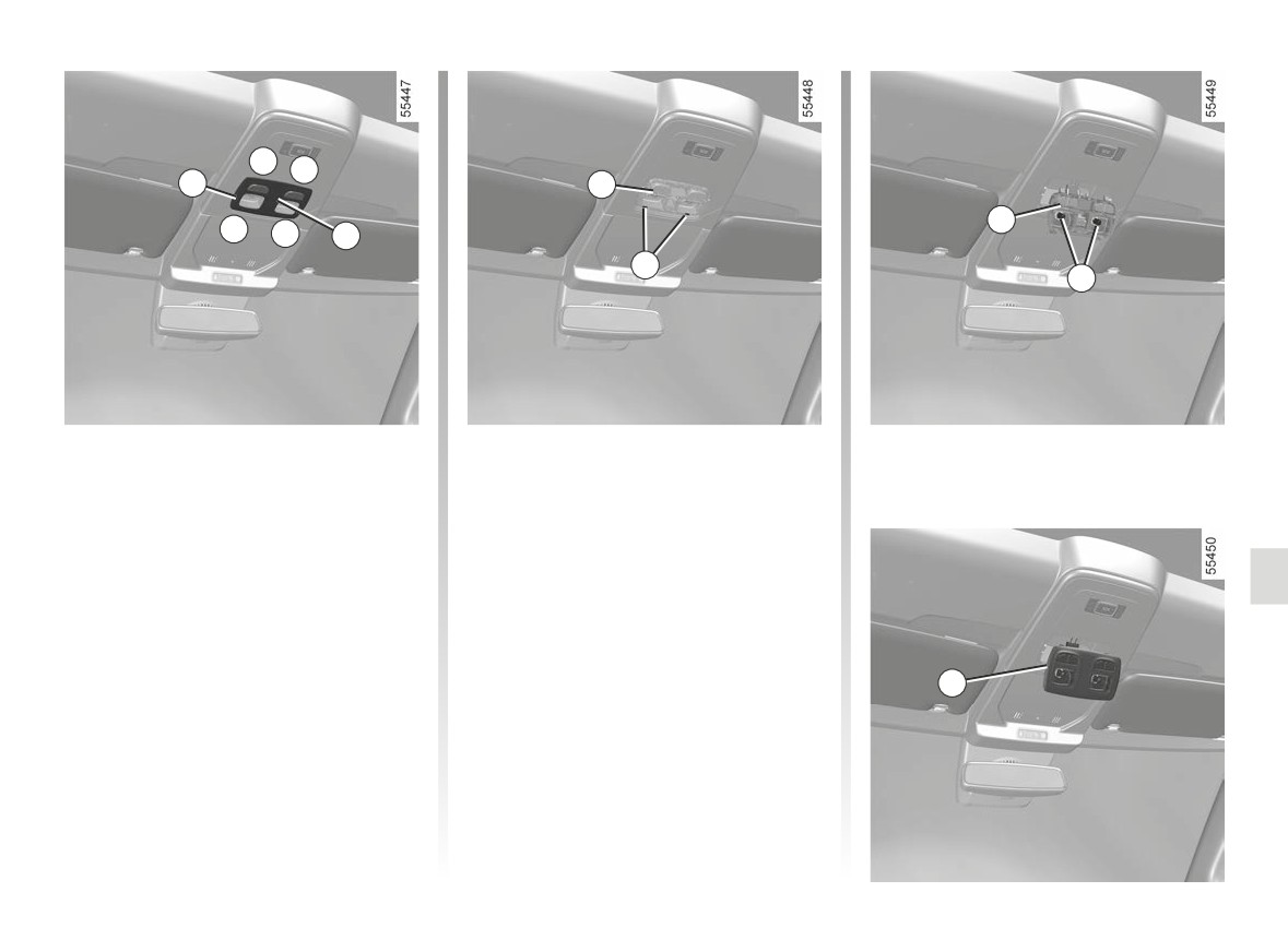
INTERIOR LIGHTING: changing bulbs (2/5)
B
B
6
8
8
B
B
7
9
10
Front map reading lights 6
Refitting
(depending on the vehicle)
- Clip the lens 7 on to the bulb holder 8;
- Unclip the lens 7 (using a tool such
- clip in the reading spots block 6 until
as a flat screwdriver), positioned
the unit clicks;
at B;
- make sure that the reading spots
- unclip and release the bulb
block is correctly positioned and
holder 8 using the tabs 9;
locked into place.
- remove the bulb concerned.
Type of bulb 10: W5W.
6
5.23
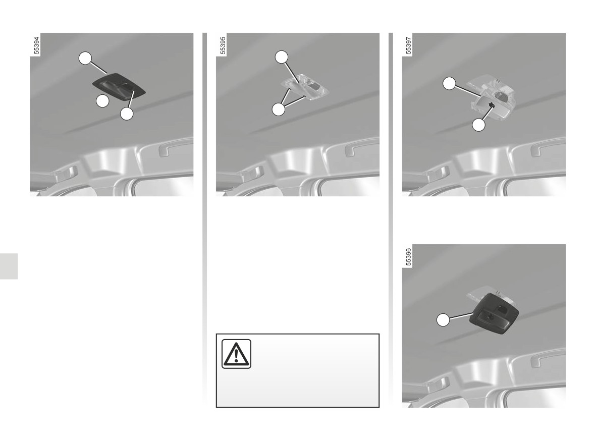
INTERIOR LIGHTING: changing bulbs (3/5)
11
13
13
C
14
12
15
Rear reading spot 11
Refitting
(depending on the vehicle)
- Clip the lens
12 on to the bulb
- Unclip the lens 12 (using a tool such
holder 13;
as a flat screwdriver), positioned
- clip in the reading spots block 11 until
at C;
the unit clicks;
- unclip and release the bulb
- make sure that the reading spots
holder 13 using the tabs 14;
block is correctly positioned and
- remove the bulb concerned.
locked into place.
Type of bulb 15: W5W.
11
The bulbs are under pres-
sure and can break when
replaced.
Risk of injury.
5.24
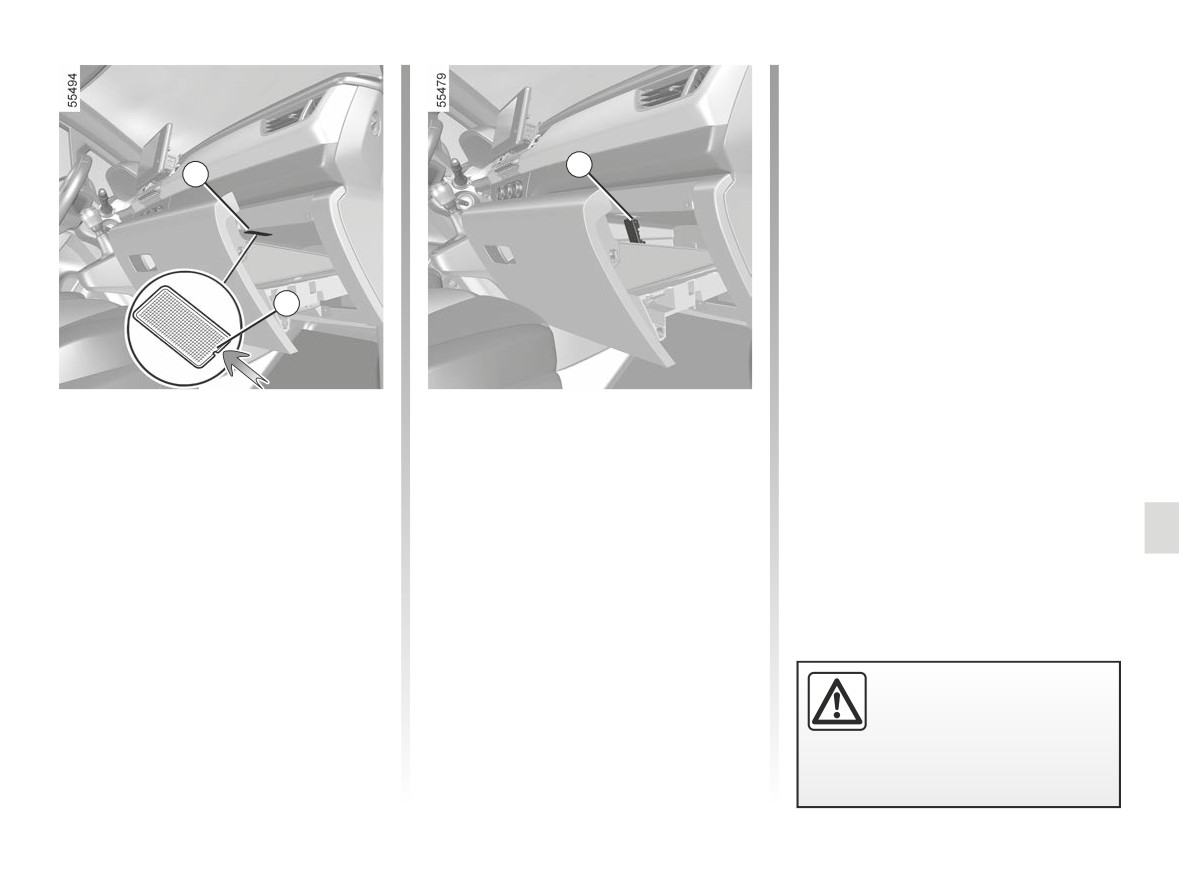
INTERIOR LIGHTING: changing bulbs (4/5)
16
16
17
Glove box light 16
Remove the bulb concerned.
(depending on the vehicle)
Bulb type: W5W.
Unclip light 16 using a flat-blade screw-
driver or similar) by pressing on the
tab 17 to move the light towards the
inside of the unit.
The bulbs are under pres-
sure and can break when
replaced.
Risk of injury.
5.25
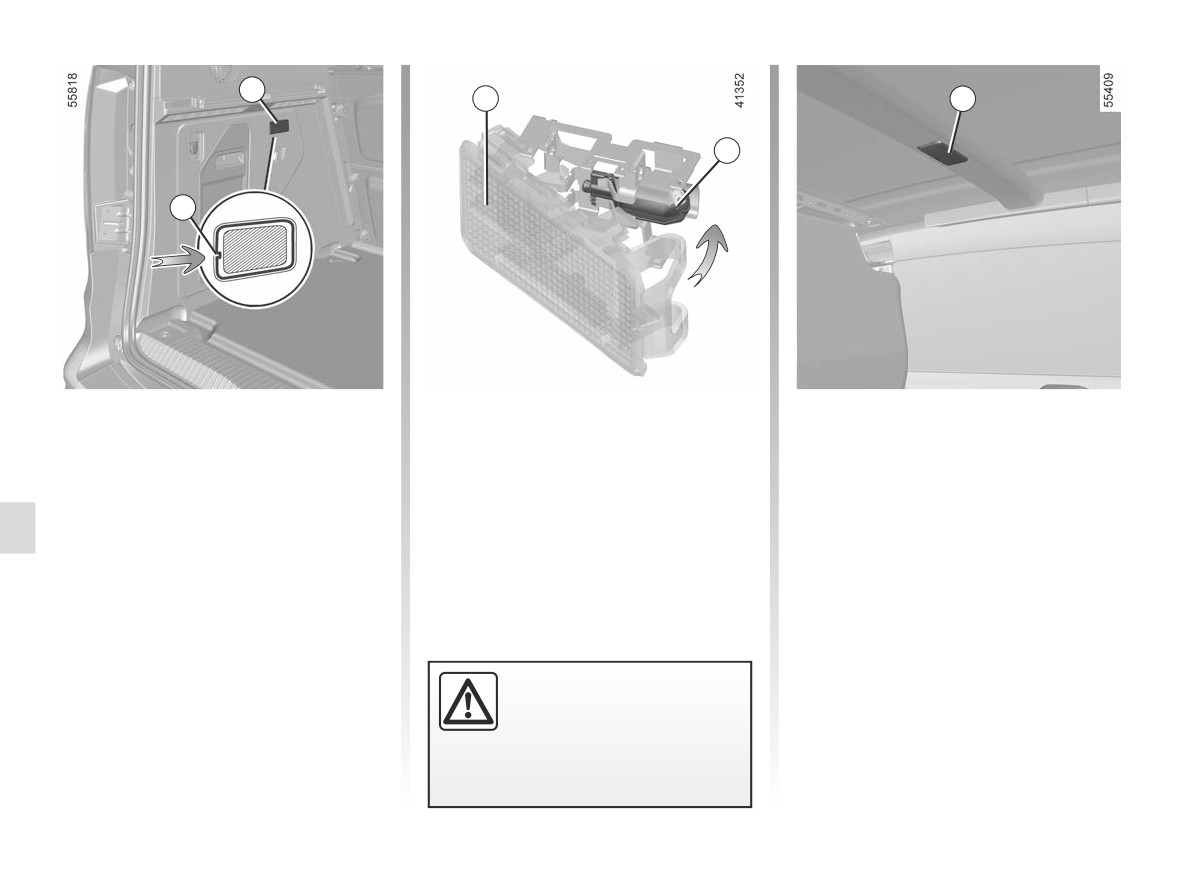
INTERIOR LIGHTING: changing bulbs (5/5)
18
20
22
21
19
Luggage compartment
Release the lens 20 and access the
Halogen rear light 22
bulb 21.
light 18
Unclip the ceiling light diffuser using a
Type of bulb 21: W5W.
flat blade screwdriver or similar.
Unclip light 18 (using a flat-blade screw-
driver or similar), by pressing on tab 19
Pull the bulb to remove it from its hous-
to move the light towards the inside of
ing.
the luggage compartment.
Bulb type: W6W
Remove the bulb concerned.
Replace the bulb and refit the lens.
Type of bulb: W5W.
LED rear light 22
Consult an approved dealer.
The bulbs are under pres-
sure and can break when
replaced.
Risk of injury.
5.26
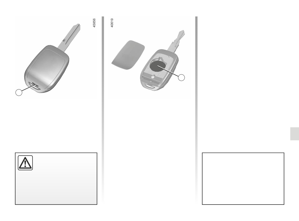
REMOTE CONTROL KEY: BATTERY: battery (1/2)
2
1
Replacing the battery
Note: It is not advisable to touch the
electronic circuit in the key cover when
Open the case at slot 1 using a flat-
replacing the battery.
blade screwdriver or similar, and re-
place the battery 2, observing the type
When refitting, ensure that the cover is
and polarity shown on the back of the
correctly clipped on and the screw tight-
cover.
ened.
If they need to be replaced,
be sure to use the same
The batteries are available from ap-
or equivalent type of bat-
proved Dealers, and their service
tery (consult an Approved
life approximately two years.
Dealer).
Check that there is no dye on the
battery: risk of an incorrect electri-
cal contact.
5.27
REMOTE CONTROL KEY: BATTERY: battery (2/2)
Operating faults
If the battery is too weak to ensure cor-
rect operation, you will still be able to
start and lock/unlock the vehicle
➥ 1.29.
Do not throw away your used bat-
Precautions relating to
teries; give them to an organisation
batteries:
responsible for collecting and recy-
- keep (new or used) bat-
cling batteries.
teries out of reach of chil-
dren;
- do not swallow batteries;
When replacing:
Risk of chemical burns which
- make sure that the batter-
may lead to death.
ies are correctly inserted.
- if ingested or inserted into any
part of the body, consult a doctor
Risk of explosion.
as soon as possible.
- if the flap does not close cor-
rectly, do not use and keep out of
reach of children.
5.28
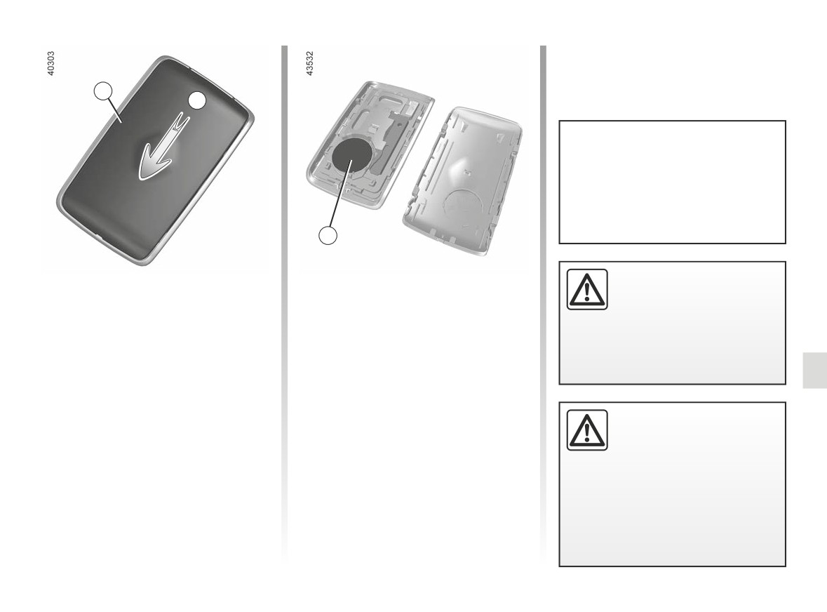
“HANDS-FREE” CARD: battery (1/2)
1
A
The batteries are available from ap-
proved Dealers, and their service
life approximately two years. Check
that there is no dye on the battery:
risk of an incorrect electrical con-
tact.
2
If they need to be replaced,
Replacing the battery
When refitting, proceed in the reverse
be sure to use the same
order, then press one of the buttons on
When the message “Keycard Battery
or equivalent type of bat-
the card four times, close to the vehicle:
Low” appears on the instrument panel,
tery (consult an Approved
the next time the vehicle is started, the
replace the battery in the card:
Dealer).
message will disappear.
- slide the rear casing 1 downwards
while pressing on zone A;
Check that the cover is clipped shut.
- remove the battery cover 2;
Note: Do not touch the electronic circuit
- remove the battery by pressing on
or contacts on the card when replacing
one side and lifting the other;
the battery.
When replacing:
- replace it according to the direc-
tion and template shown inside the
- make sure that the batter-
cover.
ies are correctly inserted.
Risk of explosion.
- if the flap does not close cor-
rectly, do not use and keep out of
reach of children.
5.29
“HANDS-FREE” CARD: battery (2/2)
Operating faults
If the battery is too weak to ensure cor-
rect operation, you will still be able to
start and lock/unlock the vehicle
➥ 1.29.
Precautions relating to
batteries:
- keep (new or used) bat-
teries out of reach of chil-
dren;
- do not swallow batteries;
Risk of chemical burns which
may lead to death.
- if ingested or inserted into any
part of the body, consult a doctor
as soon as possible.
Do not throw away your used bat-
teries; give them to an organisation
responsible for collecting and recy-
cling batteries.
5.30
BATTERY: troubleshooting (1/2)
To avoid all risk of sparks:
Connecting a battery charger
-
Ensure that any power consumers
The battery charger must be com-
(courtesy lights, etc.) are switched
patible with a battery with nominal
off before disconnecting or recon-
voltage of 12 volts.
necting a battery;
Do not disconnect the battery when the
-
when charging, stop the charger
engine is running. Follow the instruc-
before connecting or disconnecting
tions given by the manufacturer of
the battery;
the battery charger you are using.
-
do not place metal objects on the
battery as this could create a short
Handle the battery with care
circuit between the terminals;
as it contains sulphuric acid,
-
always wait at least five minutes
which must not come into
after the engine has been switched
contact with eyes or skin. If
off before disconnecting a battery;
it does, wash the affected area with
-
make sure that you reconnect the
plenty of cold water. If necessary,
battery terminals after refitting.
consult a doctor.
Keep naked flames, red hot objects
and sparks away from the battery
components as there is a risk of
explosion.
Special procedures may be
Please note when working close to
required to charge some
the engine that it may be hot. In ad-
batteries. Contact your ap-
dition, the engine cooling fan may
proved dealer.
Avoid all risk of sparks which may
start at any moment. The
cause an immediate explosion, and
warning light in the engine compart-
charge the battery in a well venti-
ment reminds you of this.
lated area.
Risk of injury.
Before carrying out any
Risk of serious injury.
action in the engine com-
partment, you must switch
off the ignition.
➥ 2.4
➥ 2.5.
5.31
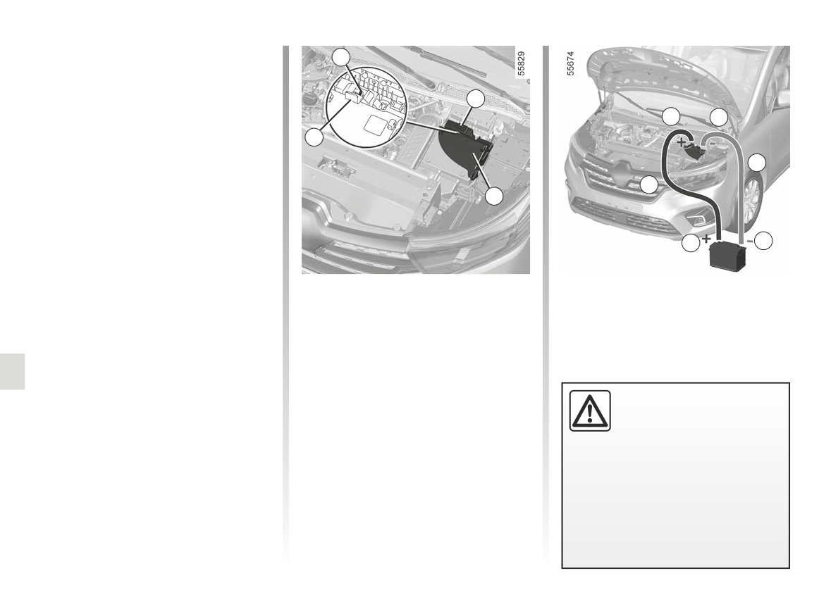
BATTERY: troubleshooting (2/2)
Starting the vehicle using the
1
battery from another vehicle
If you have to use the battery from an-
2
other vehicle to start, obtain suitable
jump leads (with a large cross section)
1
4
from an approved dealer or, if you al-
2
ready have jump leads, ensure that
they are in perfect condition.
B
The two batteries must have an iden-
A
tical nominal voltage: 12 volts. The
3
battery supplying the current should
have a capacity (amp-hours, Ah) which
is at least the same as that of the dis-
6
5
charged battery.
Ensure that there is no risk of contact
Lift the red cover on box 2 located
Start the engine, and as soon as it starts
between the two vehicles (risk of short
behind the battery.
running, disconnect cables A and B in
circuiting when the positive terminals
reverse order ( 4 - 5 - 6 - 1).
are connected) and that the discharged
Connect the positive cable A to the
After repairing, ensure that the protec-
battery is properly connected. Switch
support 1 ( + ) located under the box
tive foam and the cover 3 are in place.
off your vehicle ignition.
cover 2, then to the terminal 6 ( + ) of
the battery supplying the current.
Start the engine of the vehicle supply-
ing the current and run it at an interme-
Remove the cover 3 and the protective
foam located underneath. Connect the
Check that there is no con-
diate engine speed.
negative cable B to terminal 5 ( - ) of
tact between leads A and B
the battery supplying the current then
and that the positive lead A
to the metal cable 4 ( - ) of the dis-
is not touching any metal
charged battery.
parts on the vehicle supplying the
current.
Risk of injury and/or damage to
the vehicle.
5.32
FITTING A RADIO
1
2
-
In all cases, it is very important to
follow the manufacturer’s instruc-
tions carefully.
-
The specifications of the brack-
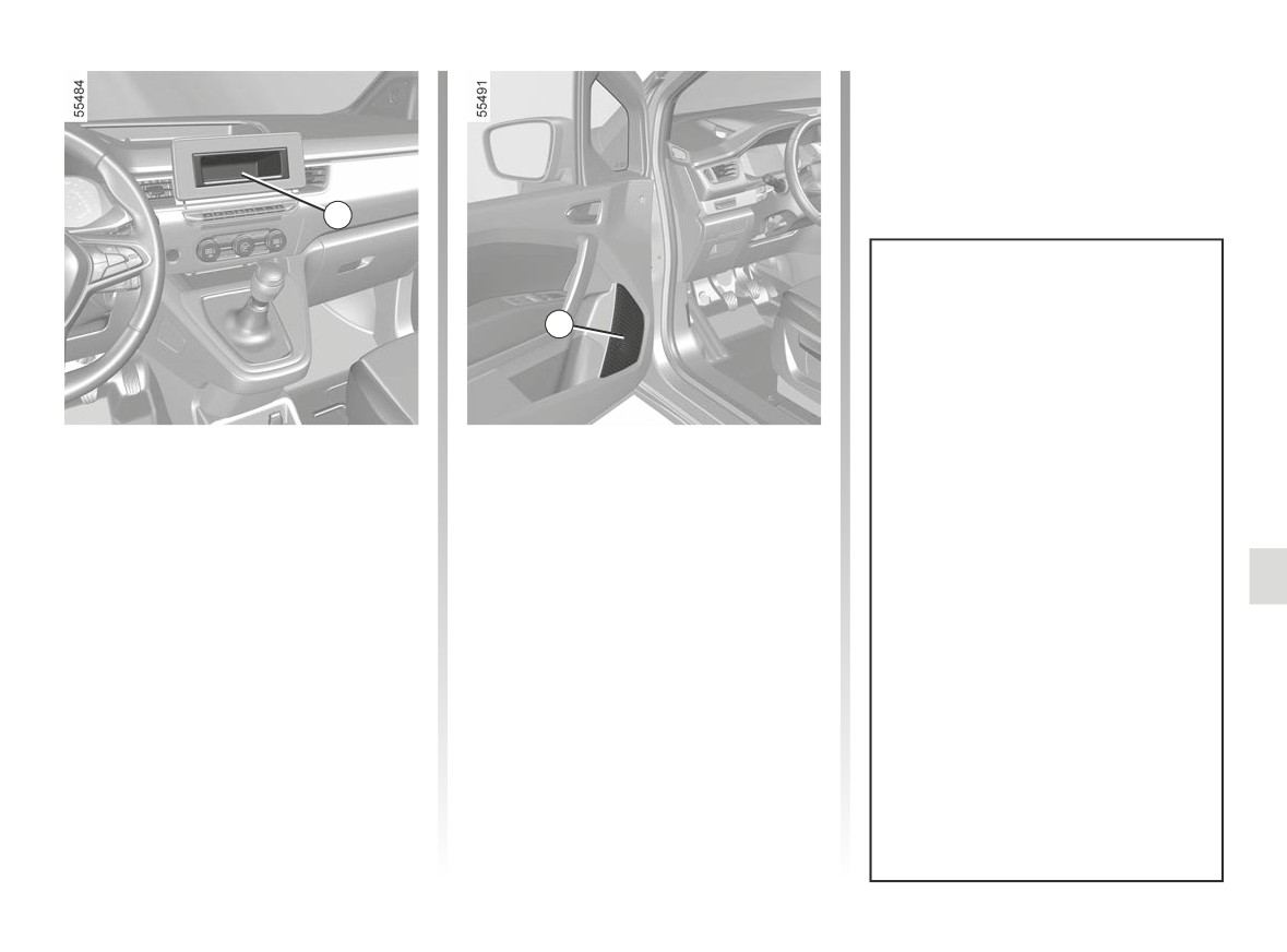
Radio location 1
Front door speakers 2
ets and wires (available from our
Unclip the blanking cover. The connec-
To install any equipment, please con-
network) vary depending on the
tions: ( + aerial) and ( - supply and
sult an authorised dealer.
equipment level of your vehicle
speaker) are located behind it.
and the type of radio.
Consult an approved Dealer to
find out the correct part number.
-
No work may be carried out on
the vehicle’s electrical or radio
circuits, except by approved
dealers: an incorrectly connected
system may result in damage
being caused to the electrical
equipment and/or the compo-
nents connected to it.
5.33
ACCESSORIES
Electrical and electronic accessories
Before installing this type of accessory (particularly for transmitters/receivers: frequency bandwidth, power level, po-
sition of the aerial, etc.), make sure it is compatible with your vehicle. You can get advice from an authorised dealer.
Connect accessories with a maximum power of 120 Watts only. Fire hazard. When several accessory sockets are
used at the same time, the total power of the connected accessories must not exceed 180 watts.
No work may be carried out on the vehicle’s electrical or radio circuits, except by authorised dealers: an incorrectly connected
system may result in damage being caused to the electrical equipment and/or the components connected to it.
If the vehicle is fitted with any aftermarket electrical equipment, make sure that the installation is correctly protected by a fuse.
Establish the rating and position of this fuse.
Using the diagnostic socket
The use of electronic accessories on the diagnostic socket may cause serious disturbance to the vehicle’s electronic systems.
For your safety we recommend that you use only electronic accessories approved by the manufacturer, consult an Approved
Dealer. Serious accident risk.
Use of transmitting/receiving devices (telephones, CB equipment etc.).
Telephones and CB equipment with integrated aerials may cause interference to the electronic systems originally fitted to the
vehicle: it is advisable only to use equipment with an external aerial. Furthermore, we remind you of the need to conform
to the legislation in force concerning the use of such equipment.
Fitting aftermarket accessories
If you wish to install accessories on the vehicle: please contact an authorised dealer. Also, to ensure the correct operation of
your vehicle, and to avoid any risk to your safety, we recommend that you use only accessories specifically designed for your
vehicle, which are the only accessories for which the manufacturer will provide a warranty.
If you are using an anti-theft device, only attach it to the brake pedal.
Obstructions to the driver
On the driver’s side, only use mats suitable for the vehicle, attached with the pre-fitted components, and check the fitting regu-
larly. Do not lay one mat on top of another. There is a risk of wedging the pedals.
5.34
FUSES (1/3)
1
2
2
3
1
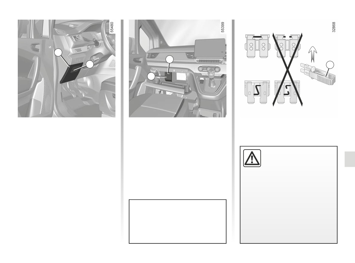
Fuse boxes
Tweezers 3
If any electrical component does not
Remove the fuse using the tweezers 3
work, check the condition of the fuses.
on the back of the flap.
To remove the fuse from the tweezers,
Passenger compartment fuses
slide the fuse to the side.
Check the fuse in question
Place your hand in location 2 and pull to
It is not advisable to use the free fuse
and replace it, if neces-
open the flap 1.
locations.
sary, by a fuse of the same
Depending on the vehicle, to identify
rating.
the fuses, refer to the fuse allocation
If a fuse is fitted with too high a
label located at the back of the flap 1
rating, it may cause the electrical
and shown on the following pages.
circuit to overheat (risk of fire) in the
event of an item of equipment using
an excessive amount of current.
To comply with current legislation, or
as a precaution, you can obtain an
emergency kit from your approved
dealer containing a set of spare
bulbs and fuses.
5.35
FUSES (2/3)
Allocation of fuses
(the presence of certain fuse depends on the vehicle equipment level)
Symbol
Allocation
H
Windscreen washer
Á
Front headlights
¼
Hazard warning lights
Ì
Horn
Ý
Towbar socket
×
Brake lights, passenger compartment central unit
Use the fuse allocation label in the
E
Screen washer, rear lights
storage compartment to identify the
fuses.
Certain fuses should only be re-
D
Direction indicators
placed by a qualified professional.
These fuses are not listed on the
label.
ë
Accessories socket
Only change the fuses represented
on the label.
Electric windows
5.36
FUSES (3/3)
A
Please note when work-
ing close to the engine that
it may be hot. In addition,
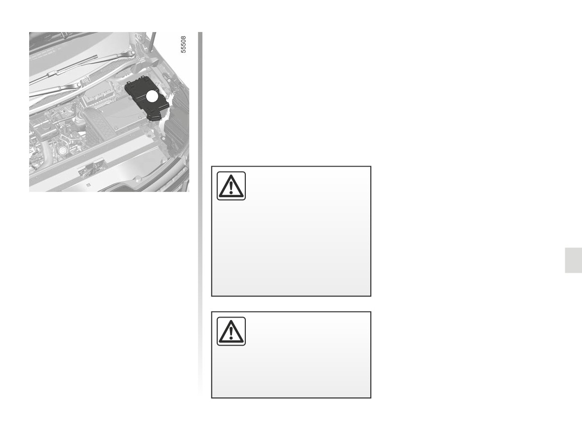
Fuses in engine compartment A
the engine cooling fan may
Some functions are protected by fuses
located in the engine compartment
start at any moment. The
(unit A).
warning light in the engine compart-
ment reminds you of this.
However, because of their reduced
accessibility, we advise you to have
Risk of injury.
your fuses replaced by an approved
Dealer.
Before carrying out any
action in the engine com-
partment, you must switch
off the ignition.
➥ 2.4 or
➥ 2.5.
5.37
WIPER BLADES: replacement (1/2)
B
A
1
2
3
4
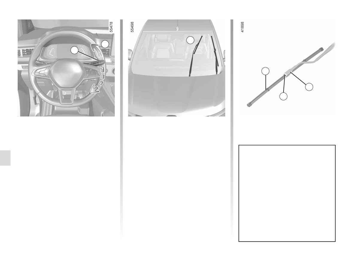
Replacing the windscreen
To refit
wiper blades 2
To refit the wiper blade 2, insert it in its
To replace the wipers, first put them in
housing in the arm 3, then clip it until
the service positionB.
you hear a click. Make sure that the
With the ignition on and the engine
blade is correctly locked in position.
stopped:
To return the blades to lowered posi-
- move the stalk twice in succession 1
Check the condition of the wiper
tion, make sure that the blades are
to position A (single sweep): the
blades. You are responsible for their
folded down onto the windscreen then
wiper blades will stop in the service
service life:
set the 1 stalk to position A (single
position B away from the bonnet;
- clean the blades, windscreen and
sweep): the windscreen wiper blades
- lift the wiper arm 3;
rear screen regularly with soapy
will fold into the bonnet when the igni-
- lower the 4 tab then remove the
water;
tion is switched on.
blade 2.
- do not use them when the wind-
screen or rear screen are dry;
- free them from the windscreen or
rear screen when they have not
been used for a long time.
5.38
WIPER BLADES: replacement (2/2)
5
C
5
C
- In frosty weather, make
6
sure that the wiper blades
6
are not stuck by ice
(to
avoid the risk of the motor
overheating).
- Check the condition of the wiper
blades. Replace the wiper blades
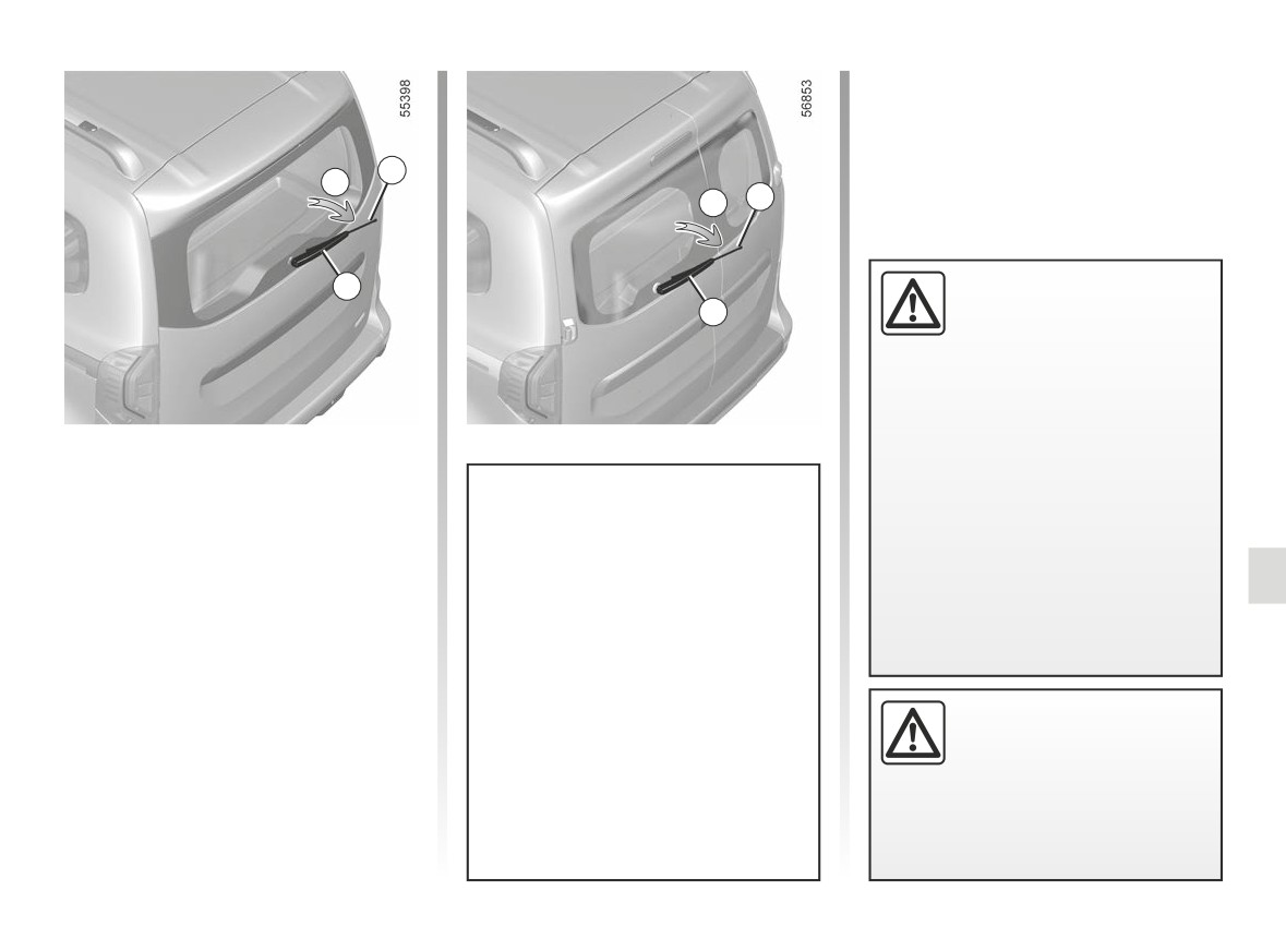
Rear screen wiper blade 5
as soon as they begin to lose ef-
Stalk in stop position (deactivated):
ficiency
(approximately once a
- lift the wiper arm 6;
year).
- turn the blade horizontally 5 (move-
When changing the blade, when it
ment C) until it unclips;
has been removed, do not let the
Check the condition of the wiper
- remove the blade by pulling it.
wiper arm fall against the window:
blades.
risk of breaking the window.
To refit
- clean the blades, windscreen and
rear screen regularly with soapy
To refit the wiper blade, proceed in re-
water;
verse order to removal. Make sure that
the blade is correctly locked in position.
- do not use them when the wind-
screen or rear screen are dry;
Before changing the rear
wiper blade, make sure the
- free them from the windscreen or
stalk is in the stop position
rear screen when they have not
(deactivated).
been used for a long time.
Risk of injury.
5.39
TOWING: breakdown recovery (1/2)
Before carrying out any towing, posi-
The speed specified by current legis-
1
tion the gearbox in neutral position (po-
lation for towing must always be ob-
sition N on vehicles equipped with an
served. If you are driving the towing
automatic gearbox), unlock the steering
vehicle, do not exceed the permissible
column then release the parking brake.
towing weight for your vehicle. ➥ 6.10.
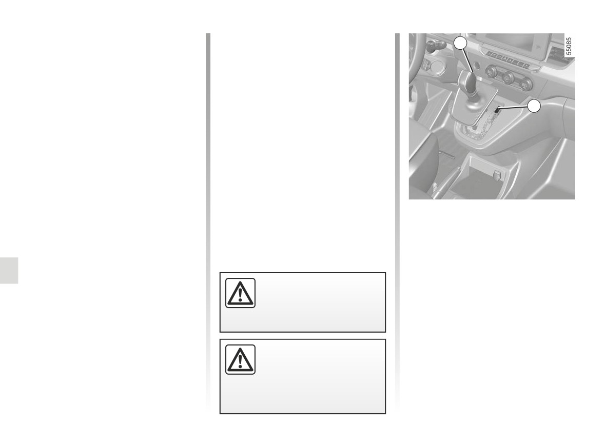
Steering column unlocking
Towing a vehicle fitted with
2
Insert the key into the ignition, set to
an automatic gearbox
“On” ON 2 position or, depending on
the vehicle, with the card in the pas-
Transport the vehicle on a trailer or tow
senger compartment, press the engine
it with the front wheels off the ground.
start button for approximately two sec-
In exceptional circumstances, you
onds.
may tow it with all four wheels on the
ground, only in a forward gear, with the
Reposition the lever to neutral (position
gearbox in neutral position N, over a
N for vehicles fitted with an automatic
maximum distance of 50 miles (80 km)
gearbox).
and not exceeding a speed of 16 mph
When starting, if the lever is locked in
The steering column unlocks, the ac-
(25 km/h).
position P even though you are press-
cessory functions are powered: you
ing the brake pedal, the lever can be re-
can use the vehicle’s lights (direction
leased manually in order to unlock the
indicators, brake lights, etc.). At night
drive wheels.
the vehicle must have its lights on.
To do this, unclip the base of the gaiter
Depending on the vehicle, once you
and press the 2 button while simultane-
When the engine is stopped,
have finished towing, press the engine
ously pressing the 1 button on the lever
steering and braking assist-
start button twice (risk of running down
to unlock the lever and shift to position
ance are not operational.
the battery).
N.
Contact an authorised dealer as soon
as possible.
Leave the card in the vehi-
cle during towing.
Risk of the steering
column locking.
5.40
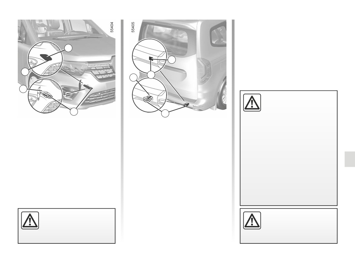
TOWING: breakdown recovery (2/2)
Tighten the towing hitch 5 fully: first
by hand until it stops, then finish by
locking it with the wheel brace or, de-
pending on the vehicle, the lever.
3
Only use the towing hitch 5 and the
wheelbrace or lever provided with the
6
tools. ➥ 5.8.
A
B
7
4
- Use a rigid towing bar.
If a rope or cable is used
(where the law allows this),
5
5
the vehicle being towed
Only use the front 4 and rear 7 towing
Access to towing points
must be able to brake.
points (never use the driveshafts or any
-
A vehicle must not be towed if it is
other part of the vehicle). These towing
Front towing point 4
not fit to be driven.
points may only be used for pulling.
-
Avoid accelerating or braking
Unclip the cover 3 by inserting a flat-
They must never be used for lifting the
suddenly when towing, as this
blade screwdriver or similar into the
vehicle directly or indirectly.
may result in damage being
groove A.
caused to the vehicle.
-
In all cases, it is advisable not to
Rear towing point 7
exceed 15.5 mph (25 km/h).
Unclip the cover 6 by inserting a flat-
blade screwdriver or similar into the
groove B.
Ensure that the towing eye
Do not leave the tools unse-
is bolted correctly.
cured inside the vehicle as
they may come loose under
Risk of losing the towed
braking.
object.
5.41
OPERATING FAULTS (1/8)
Using the card
POSSIBLE CAUSES
WHAT TO DO
The card does not lock or unlock the
Card battery is flat.
Replace the battery. You will still be able to
doors.
lock/unlock and start your vehicle. ➥ 1.29
and ➥ 2.4 or ➥ 2.5.
Use of appliances operating on the
Stop using the devices or use the key pro-
same frequency as the card (mobile
vided. ➥ 1.29.
phone, etc.).
Vehicle located in a high electromag-
Use the key that is built into the card
netic radiation zone.
➥ 1.29.
Vehicle battery flat.
The message “Place card on zone +
Place the card in the placement area
START” appears on the instrument
➥ 2.5 then press the START button.
panel.
The vehicle is started.
With the engine running, the card’s locking/
unlocking device is blocked. Turn off the ig-
nition.
Desynchronisation of the card
Unlock the driver’s door by inserting the
key integrated in the card into the door lock
➥ 1.29 then place the card in the placement
area ➥ 2.5 and press the START button to
synchronise the card.
5.42
OPERATING FAULTS (2/8)
The following advice will enable you to carry out quick, temporary repairs. For safety reasons you should always contact
an approved dealer as soon as possible.
Using the remote control
POSSIBLE CAUSES
ACTION REQUIRED
The remote control does not lock or The remote control battery is flat.
Use the emergency key.
unlock the doors.
Use of appliances operating on the same
Stop using the devices or use the key.
frequency as the remote control (mobile
phone, etc.).
Vehicle located in a high electromagnetic
Replace the battery. You will still be able to
radiation zone.
lock/unlock and start your vehicle. ➥ 1.29
Discharged battery.
and ➥ 2.4 or ➥ 2.5.
The vehicle is started.
With the engine running, the key’s locking/
unlocking device is blocked. Turn off the
ignition.
Desynchronisation of the remote control
Unlock the driver’s door by inserting the
key into the door lock ➥ 1.29, then start
the engine to synchronise the remote con-
trol ➥ 2.4.
5.43