Renault Alaskan (2018 year). Manual in english - page 13
ENGINE OIL
CHECKING ENGINE COOLANT LEVEL
Improper servicing can result in reduced heater per-
CHECKING ENGINE OIL LEVEL
formance and engine overheating.
WARNING
• To avoid being scalded, never change the cool-
ant when the engine is hot.
• Never remove the radiator or coolant reservoir
cap when the engine is hot. Serious burns
could be caused by high pressure fluid escap-
ing from the radiator.
JVM0528XZ
• Avoid direct skin contact with used coolant. If
JVM0535XZ
skin contact is made, wash thoroughly with
M9T 2.3DCI engine
M9T 2.3DCI engine
soap or hand cleaner as soon as possible.
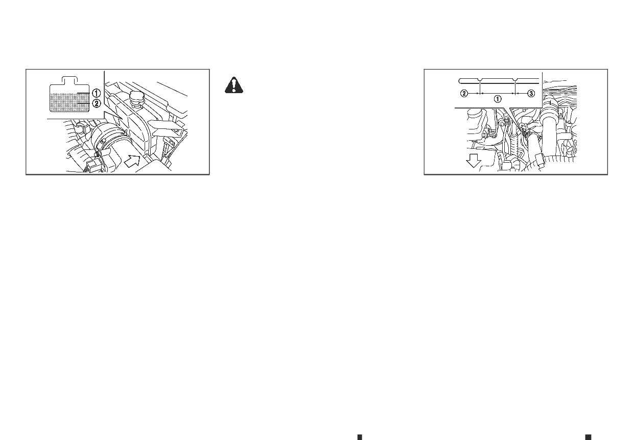
Check the coolant level in the reservoir when the
1.
Park the vehicle on a level surface and apply the
• Keep coolant out of reach of children and pets.
engine is cold. If the coolant level is below the <MIN>
parking brake.
level ➁, add coolant up to the <MAX> level ➀. If the
Engine coolant must be disposed of properly. Check
2.
Start the engine and warm it up until the engine
reservoir is empty, check the coolant level in the ra-
your local regulations.
temperature reaches the normal operating tem-
diator when the engine is cold. If there is insuffi-
perature (approximately 5 minutes).
cient coolant in the radiator, fill the radiator with
3.
Stop the engine.
coolant up to the filler opening and also add it to
the reservoir up to the <MAX> level ➀. Tighten the
4.
Wait at least 15 minutes for the engine oil to drain
cap securely after adding engine coolant.
back to the oil pan.
If the cooling system frequently requires coolant,
5.
Remove the dipstick and wipe it clean.
have it checked by an approved dealer or quali-
6.
Reinsert the dipstick all the way.
fied workshop.
7.
Remove the dipstick and check the oil level. It
CHANGING ENGINE COOLANT
should be within the range ➀.
Contact an approved dealer or qualified workshop
8.
If the oil level is below ➁, remove the oil filler cap
if replacement is required.
and pour the recommended oil into the opening.
Major engine cooling system repair should be per-
Do not overfill ➂.
formed by an approved dealer or qualified work-
When filling the engine oil, do not remove the
shop. The service procedures can be found in the
dipstick.
appropriate Service Manual.
8-6
Maintenance and do-it-yourself
AdBlue® TANK (where fitted for
diesel engine model)
9. Recheck the oil level with the dipstick.
REFILLING THE AdBlue® TANK
3.
Place the ignition switch in the OFF position.
CAUTION
When the [Refill AdBlue] warning appears in the ve-
4.
Open the AdBlue® filler lid.
hicle information display, refill the AdBlue® tank be-
5.
Remove the AdBlue® tank cap by turning it anti-
• The oil level should be checked regularly. Op-
erating your vehicle with an insufficient
fore the tank is empty (see “AdBlue® Selective Cata-
clockwise.
amount of oil can damage the engine, and
lytic Reduction (SCR) system (where fitted for diesel
6.
Refill the AdBlue® tank.
such damage is not covered by the warranty.
engine model)” in the “5. Starting and driving” sec-
tion for the AdBlue® warning display.) Refill the Ad-
7.
Securely install the AdBlue® tank cap.
• It is normal to add some oil between oil main-
Blue® tank according to the procedures shown in
8.
Close the AdBlue® filler lid.
tenance intervals or during the running-in pe-
this section.
riod, depending on the severity of operating
9.
Place the ignition switch in the ON position and
conditions.
CAUTION
wait for approximately 1 minute until the [Refill
AdBlue] warning turns off.
CHANGING ENGINE OIL AND OIL
• Use only AdBlue®. Using other fluids will dam-
age the AdBlue® Selective Catalytic Reduction
NOTE
FILTER
(SCR) system.
In the case that the [ENG can't start Refill Ad-
Contact an approved dealer or qualified workshop
• Be careful not to spill AdBlue®. If the AdBlue® is
Blue] warning was displayed, check that the
when the engine oil and oil filter require replace-
spilled on the vehicle body, wipe it away with a
warning turned off, place the ignition switch in
ment.
wet cloth immediately to avoid paint damage.
the OFF position once and then start the en-
PROTECT ENVIRONMENT
• AdBlue® residues crystallize after a period of
gine.
time and contaminate the paint surfaces. If
It is illegal to pollute drains, watercourses and soil.
the spilled AdBlue® has crystallized, use a
Use authorised waste collection facilities, including
sponge and cold water to clean it.
civil amenity sites and garages providing facilities
for disposal of used oil and used oil filters. If in doubt,
• Be careful not to inhale any ammonia vapours
contact your local authority for advice on disposal.
that may be released. Fill the AdBlue® tank in
well-ventilated areas.
The regulations concerning the pollution of the
environment will vary from country to country.
The AdBlue® tank is located underneath the vehicle.
(see “AdBlue® filler lid and cap” in the “3. Pre-driving
checks and adjustments” section for the AdBlue®
filler lid location.)
1. Apply the parking brake.
2. Automatic Transmission (AT) model: Move the
shift lever to the P (Park) position.
Manual Transmission (MT) model: Move the shift
lever to the N (Neutral) position.
Maintenance and do-it-yourself
8-7
DRIVE BELT
AUTOMATIC TRANSMISSION
POWER STEERING FLUID
FLUID (ATF) (where fitted)
7-SPEED AUTOMATIC
TRANSMISSION (AT) MODEL
Contact an approved dealer or qualified workshop
if checking or replacement is required.
CAUTION
•
Use only ATF that is recommended in the Main-
tenance Service Booklet. Do not mix with other
fluids.
•
Using automatic transmission fluid other than
JVM0534XZ
SDI1718AZ
the ATF that is recommended in the Mainte-
M9T 2.3DCI engine
nance Service Booklet may cause deteriora-
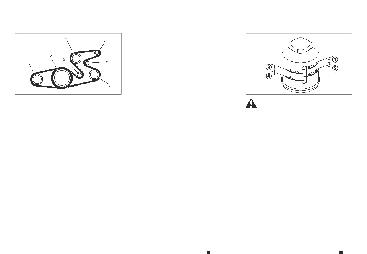
1.
Air conditioner compressor
tion in driveability and automatic transmis-
WARNING
sion durability and may damage the
2.
Crankshaft pulley
Power steering fluid is poisonous and should be
automatic transmission. Such damage is not
3.
Idler pulley
stored carefully in marked containers out of the
covered by the warranty.
reach of children.
4.
Water pump
Check the fluid level in the reservoir. The fluid level
5.
Alternator
should be checked in the HOT range (➀: HOT MAX.,
6.
Automatic tensioner
➁: HOT MIN.) at fluid temperatures of 50 to 80°C
7.
Power steering fluid pomp
(122 to 176°F) or in the COLD range (➂: COLD MAX.,
Contact an approved dealer or qualified workshop
➃: COLD MIN.) at fluid temperatures of 0 to 30°C (32
to 86°F).
if checking or replacement is required.
If it is necessary to add fluid, use only specified fluid.
Do not overfill. (Refer to the maintenance service
booklet for your vehicle for recommended types of
fluid.)
8-8
Maintenance and do-it-yourself
BRAKES
CHECKING PARKING BRAKE
CHECKING FOOTBRAKE
of the brake pad, the sound will always be heard
even if the brake pedal is not depressed. Have the
brakes checked as soon as possible if the wear
warning sound is heard.
Under some driving or climate conditions,
occasional brake squeaks, squeals or other noises
may be heard. Occasional brake noise during light
to moderate stops is normal and does not affect
the function or performance of the brake system.
The rear drum brakes do not have audible wear in-
dicators. Should you ever hear an unusually loud
SDI1447AZ
DI1020MMZ
noise from the rear drum brakes, have them
checked as soon as possible by an approved dealer
or qualified workshop.
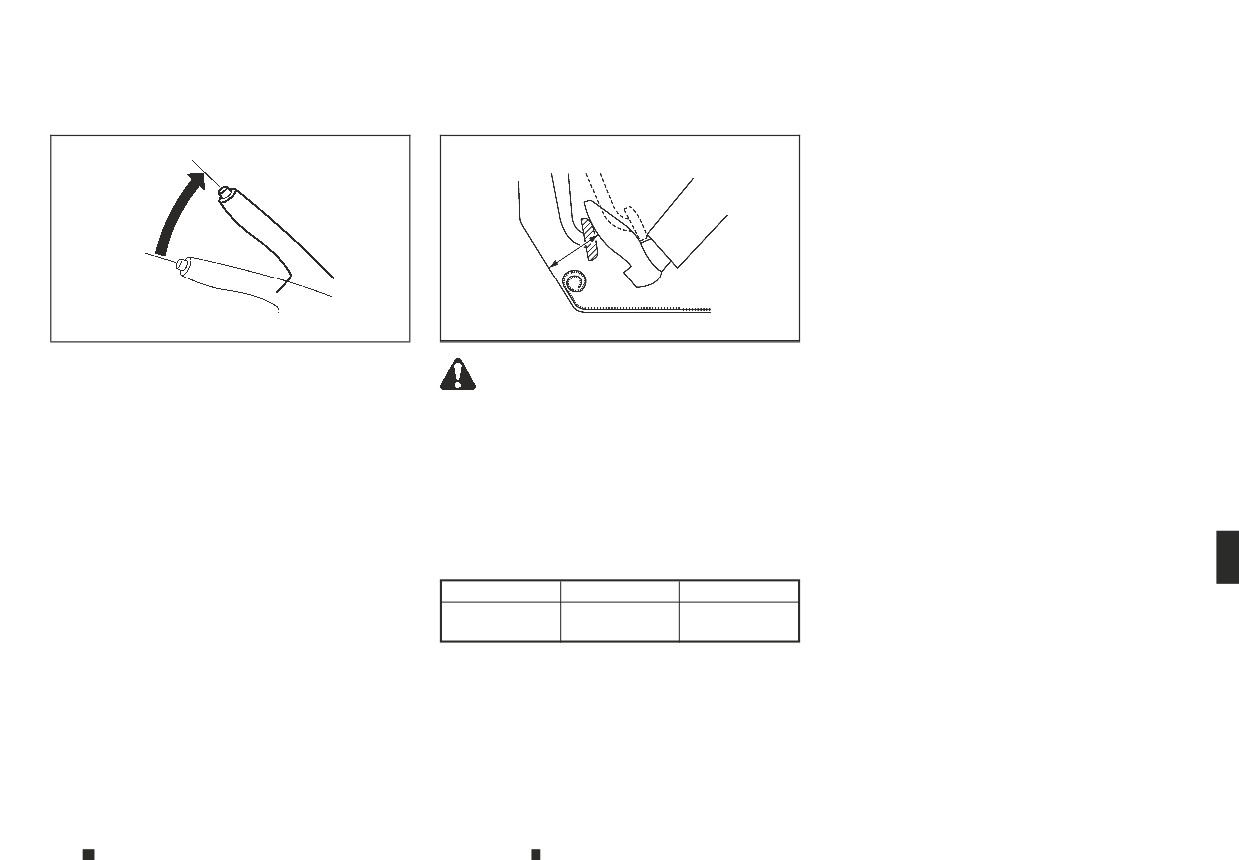
From the released position, pull the parking brake
WARNING
lever slowly and firmly. If the number of clicks is out
Proper brake inspection intervals should be
See an approved dealer or qualified workshop for
of the range listed, see an approved dealer or quali-
followed. For additional information, see a separate
a brake system check if the brake pedal height
fied workshop.
maintenance booklet.
does not return to normal.
7 to 9 clicks under a pulling force of 196 N (20
BRAKE BOOSTER
kg, 44 lb)
With the engine running, check the distance be-
tween the upper surface of the pedal and the metal
Check the brake booster function as follows:
floor. If it is out of the range listed, see an approved
1. With the engine off, depress and release the foot-
dealer or qualified workshop.
brake pedal several times. When the brake pedal
Depressing force
movement (distance of travel) remains the same
490 N (50 kg, 110 lb)
from one pedal application to the next, continue
LHD model
RHD model
on to the next step.
Diesel engine
110 mm (4.3 in)
100 mm (3.9 in)
2. While depressing the footbrake pedal, start the
model
or more
or more
engine. The pedal height should drop a little.
3. With the footbrake pedal depressed, stop the en-
Brake pad wear warning
gine. Keep the pedal depressed for about 30 sec-
The disc brake pads have audible wear warnings.
onds. The pedal height should not change.
When a brake pad requires replacement, it will make
a high pitched scraping sound when the vehicle is
in motion. This scraping sound will first occur only
when the brake pedal is depressed. After more wear
Maintenance and do-it-yourself
8-9
BRAKE FLUID
4. Run the engine for 1 minute without depressing
the footbrake pedal, then turn it off. Depress the
WARNING
footbrake pedal several times. The pedal travel
• Use only new fluid from a sealed container.
distance will decrease gradually with each de-
Old, inferior, or contaminated fluid may dam-
pression as the vacuum is released from the
age the brake system. The use of improper flu-
booster.
ids can damage the brake system and affect
If the brakes do not operate properly, have the
the vehicle's stopping ability.
brakes checked by an approved dealer or qualified
• Clean the filler cap before removing.
workshop.
• Brake fluid is poisonous and should be stored
carefully in marked containers out of the reach
JVM0450XZ
of children.
CAUTION
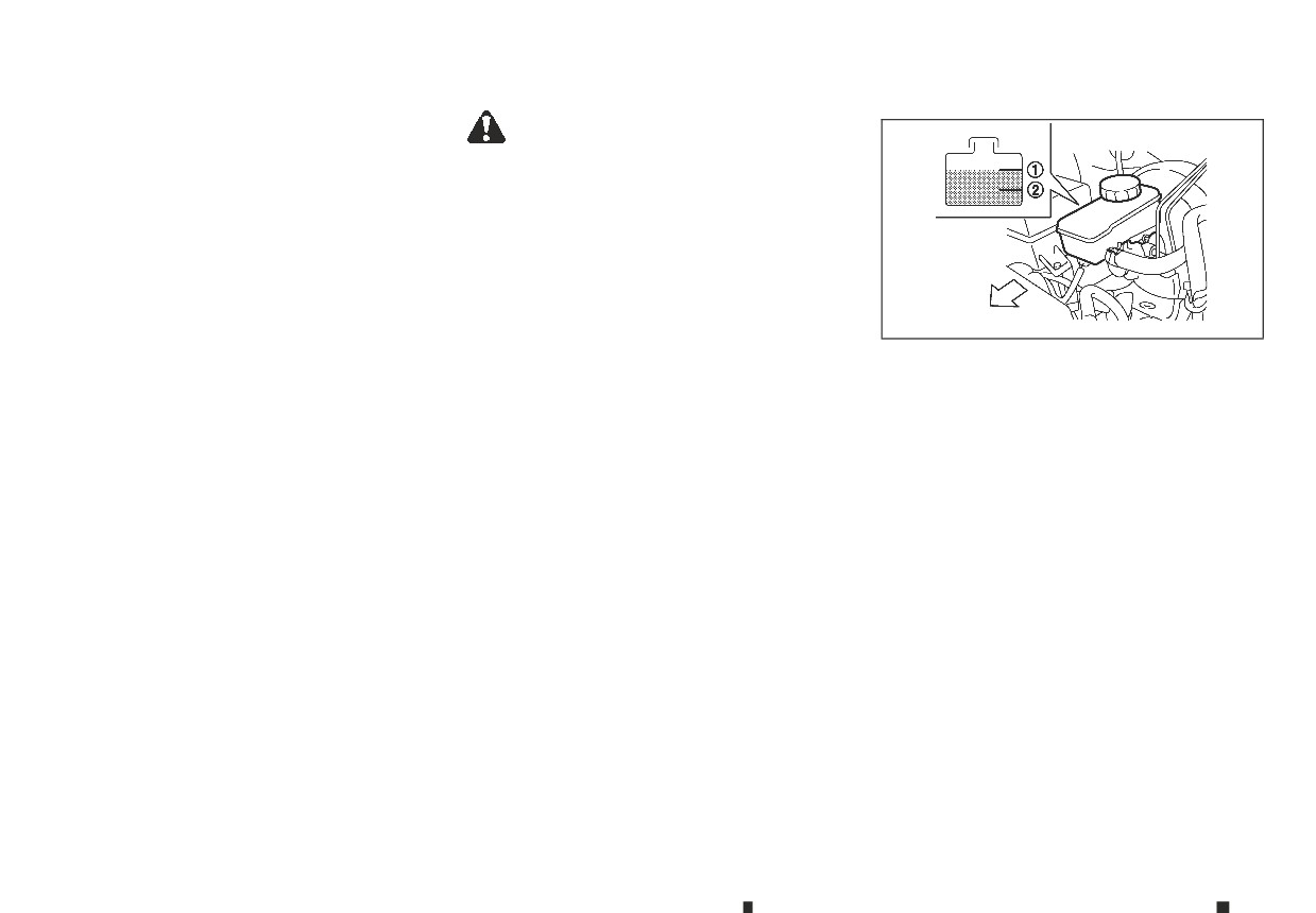
Check the fluid level in the reservoir. If the fluid is
• Refilling and checking the brake system
below the MIN line ➁, the brake warning light will
should be left to an approved dealer or quali-
illuminate. Add fluid up to the MAX line ➀.
fied workshop who will have the necessary
If fluid must be added frequently, the system should
brake fluid and technical knowledge.
be thoroughly checked by your approved dealer or
• Do not spill the fluid on painted surfaces. This
qualified workshop.
will damage the paint. If fluid is spilled, wash
with water.
For details of recommended fluids, refer to the
maintenance service booklet for your vehicle.
8-10
Maintenance and do-it-yourself
CLUTCH FLUID (where fitted)
WINDOW WASHER FLUID
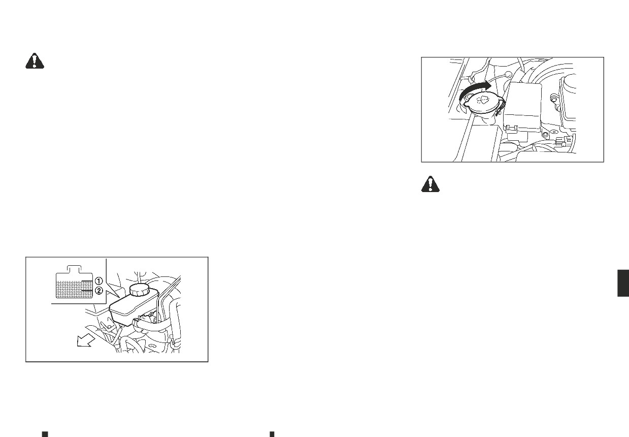
Check the fluid level in the reservoir. If the fluid is
WARNING
below the MIN line ➁, add fluid up to the MAX line
• Use only new fluid from a sealed container.
➀.
Old, inferior, or contaminated fluid may dam-
If the fluid must be added frequently, the clutch sys-
age the clutch system.
tem should be thoroughly checked by an approved
• Clean the filler cap before removing.
dealer or qualified workshop.
• Clutch fluid is poisonous and should be stored
carefully in marked containers out of the reach
of children.
CAUTION
JVM0452XZ
• Refilling and checking the clutch system
should be left to an approved dealer or quali-
fied workshop who will have the necessary
WARNING
clutch fluid and technical knowledge.
Anti-freeze is poisonous and should be stored
• Do not spill the fluid on painted surfaces. This
carefully in marked containers out of the reach of
will damage the paint. If fluid is spilled, wash
children.
with water.
Check the fluid level in the reservoir tank and add
For details of recommended fluids, refer to the
fluid if necessary.
maintenance service booklet for your vehicle.
If the low washer fluid warning (in the vehicle infor-
mation display) or the low washer fluid warning light
(in the meter) is equipped, the warning appears or
the warning light illuminates when the reservoir
tank fluid is at a low level. Add washer fluid as nec-
essary.
Add a washer solvent to the water for better clean-
ing. In the winter season, add windscreen washer
anti-freeze. Follow the manufacturer’s instructions
for the mixture ratio.
JVM0450XZ
Maintenance and do-it-yourself
8-11
BATTERY
CAUTION
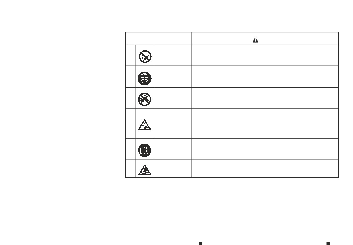
Caution symbols for battery
•
Do not substitute anti-freeze engine coolant
m WARNING
for window washer solution. This may result in
No smoking
damage to the paint.
No exposed
Never smoke around the battery. Never expose the battery to open flames
➀
Always use window washer fluid recom-
flames
or electrical sparks.
•
mended by an approved dealer or qualified
m
No sparks
workshop.
Handle the battery cautiously. Always wear eye protection glasses to
➁
Shield eyes
protect against explosion or battery acid.
m
Keep away from
Never allow children to handle the battery. Keep the battery out of reach of
➂
children
children.
m
Do not allow battery fluid to contact your skin, eyes, fabrics, or painted
surfaces. After handling the battery or battery cap, immediately wash your
hands thoroughly. If the battery fluid gets into your eyes, or onto your skin
➃
Battery acid
or clothing, flush with water immediately for at least 15 minutes and seek
m
medical attention. Battery fluid is acid. If the battery fluid gets into your eyes
or onto your skin, it could cause eyesight loss or burns.
Note operating
Before handling the battery, read this instruction carefully to ensure correct
➄
instructions
and safe handling.
m
➅
Explosive gas
Hydrogen gas, generated by battery fluid, is explosive.
m
8-12
Maintenance and do-it-yourself
VEHICLE BATTERY
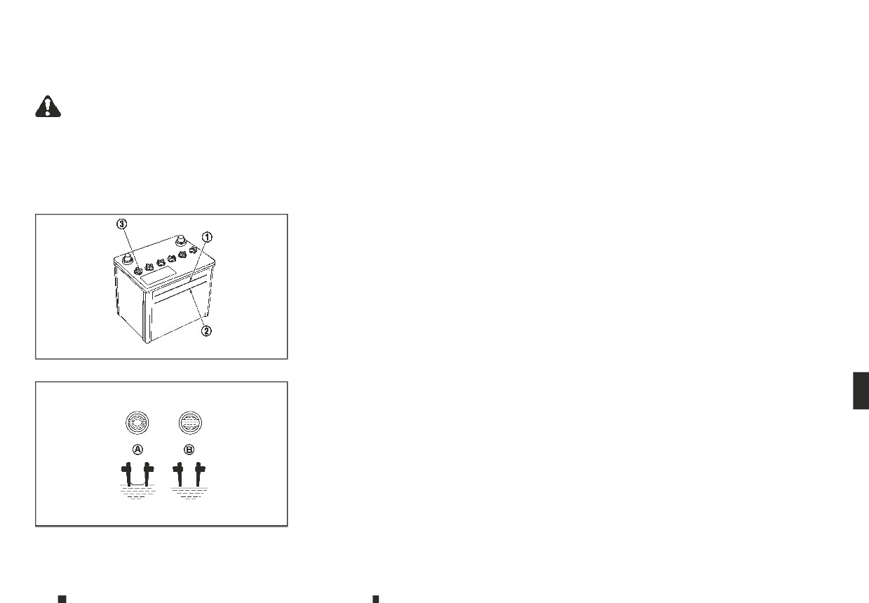
Check the fluid level in each cell. The battery fluid
REMOTE CONTROLLER BATTERY
level should be between the UPPER LEVEL ➀ and
(where fitted)
LOWER LEVEL ➁ lines.
WARNING
Remote controller battery replacement
If it is necessary to add fluid, add only deminera-
Do not operate the vehicle if the fluid in the bat-
lised/distilled water to bring the level to the indica-
CAUTION
tery is low. Low battery fluid can cause a higher
tor in each filler opening. Do not overfill.
load on the battery which can generate heat, re-
•
Be careful not to allow children to swallow the
duce battery life, and in some cases lead to an
1. Remove the cell plugs ➂ using a suitable tool.
battery and removed parts.
explosion.
2.
Add demineralised/distilled water up to the UP-
An improperly disposed battery can harm the
•
PER LEVEL ➀ line.
environment. Always confirm local regula-
Checking battery fluid level
tions for battery disposal.
If the side of the battery is not clear, check the
distilled water level by looking directly above the
•
When changing batteries, do not let dust or oil
cell; the condition
A indicates OK and the condi-
get on the components.
tion
B needs more to be added.
•
There is danger of explosion if lithium battery
3.
Replace and tighten the cell plugs.
is incorrectly replaced. Replace only with the
same or equivalent type.
•
Vehicles operated in high temperatures or un-
der severe conditions require frequent checks of
•
Do not expose the battery to excessive heat
the battery fluid level.
such as sunshine, fire, etc.
•
Keep the battery surface clean and dry. Any cor-
DI0137MDZ
rosion should be cleared with a firmly wrung out
moist cloth.
•
Make certain the terminal connections are clean
and securely tightened.
•
If the vehicle is not to be used for more than 30
days, disconnect the negative (−) battery termi-
nal cable to prevent battery discharge.
Jump starting
If jump starting is necessary, see “Jump starting” in
the “6. In case of emergency” section. If the engine
does not start by jump starting or the battery does
not charge, the battery may have to be replaced.
SDI1480DZ
Contact an approved dealer or qualified workshop
for replacing the battery.
Maintenance and do-it-yourself
8-13
• Make sure that the + side faces the bottom of
the case
C.
3. Close the lid and install the screw securely.
4. Operate the buttons to check its operation.
See an approved dealer or qualified workshop if you
need assistance for replacement.
REMOTE CONTROL KEY BATTERY
(where fitted)
Remote Control Key battery
replacement
CAUTION
•
Be careful not to allow children to swallow the
battery and removed parts.
•
An improperly disposed battery can harm the
environment. Always confirm local regula-
tions for battery disposal.
•
When changing batteries, do not let dust or oil
get on the components.
•
There is danger of explosion if lithium battery
is incorrectly replaced. Replace only with the
NDI1687
same or equivalent type.
SDI2451
•
Do not expose the battery to excessive heat
such as sunshine, fire, etc.
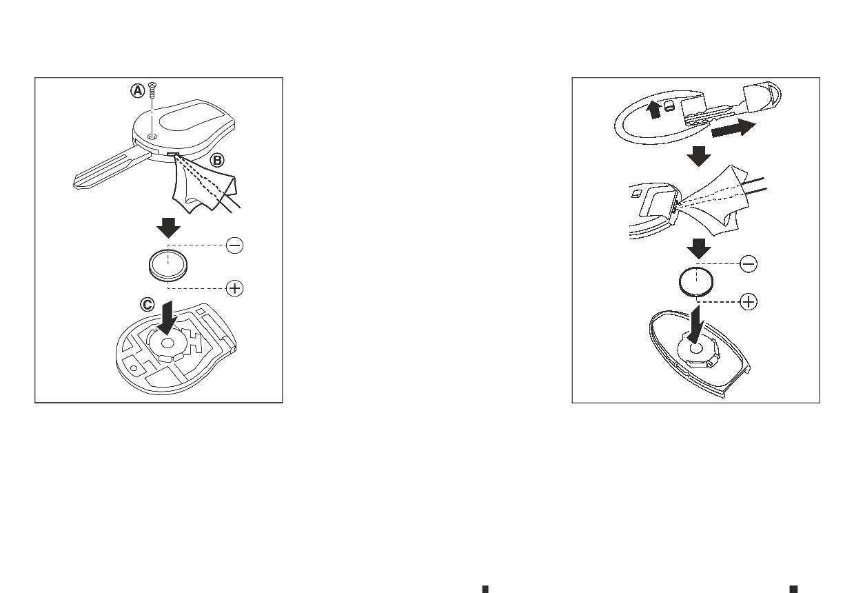
To replace the battery:
To replace the battery:
1. Use an appropriate
tool
to remove the screw
1. Release the lock knob at the back of the Remote
A and open the lid
B.
Control Key and remove the mechanical key.
2. Replace the battery with a new one.
2. Insert a small screwdriver into the slit of the cor-
ner and twist it to separate the upper part from
Recommended battery: CR1620 or equivalent
the lower part. Use a cloth to protect the casing.
• Do not touch the internal circuit and electric
3. Replace the battery with a new one.
terminals as doing so could cause a malfunc-
tion.
8-14
Maintenance and do-it-yourself
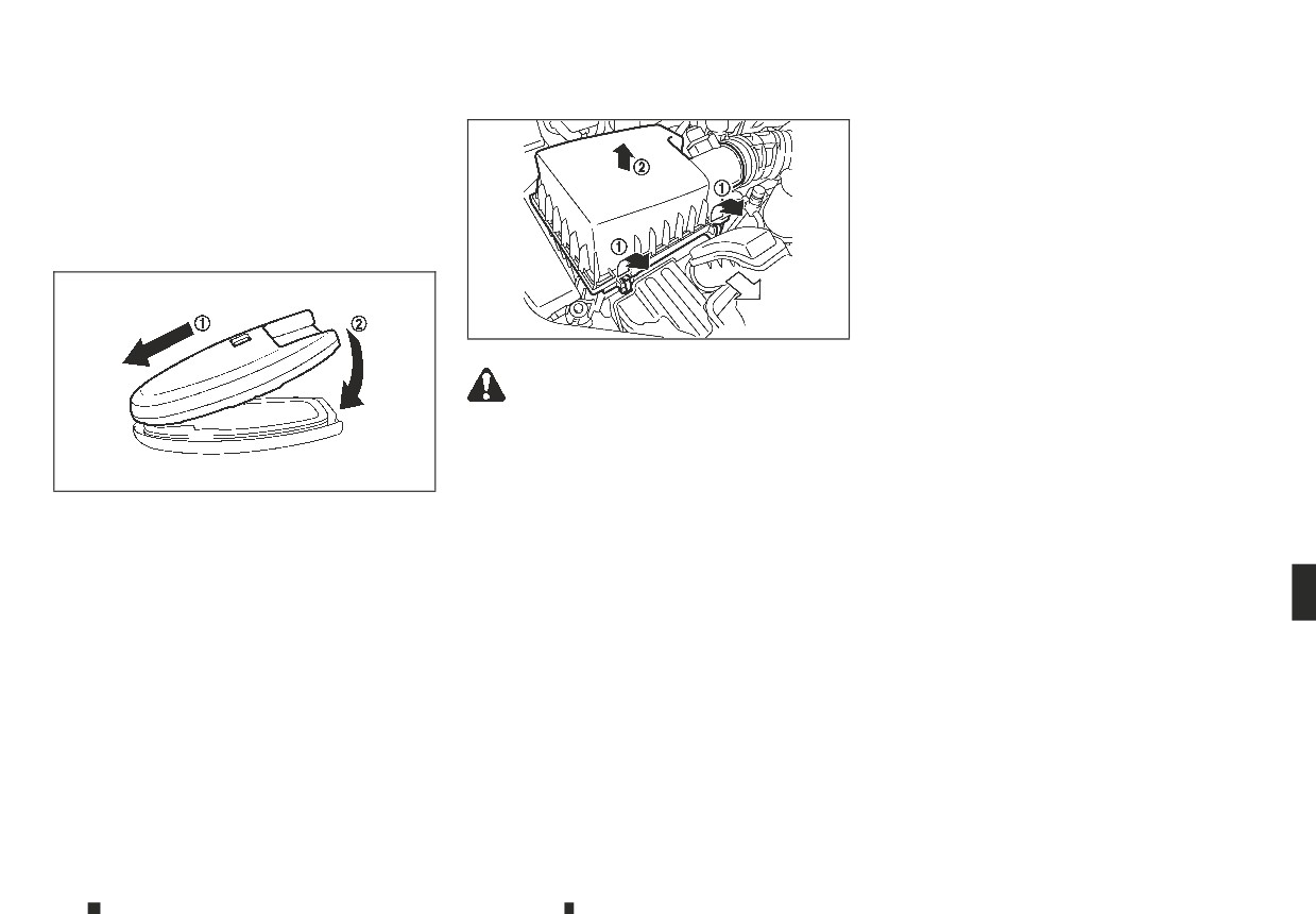
AIR CLEANER FILTER
• Recommended battery: CR2025 or equiva-
When replacing the filter, wipe the inside of the air
lent
cleaner housing and the cover with a damp cloth.
• Do not touch the internal circuit and electric
terminals as doing so could cause a malfunc-
tion.
• Make sure that the $ side faces the bottom
of the case.
JVM0451XZ
WARNING
• Operating the engine with the air cleaner filter
off can cause you or others to be burned. The
air cleaner filter not only cleans the intake air,
SDI2452Z
it also stops flame if the engine backfires. If
the air cleaner filter is not installed and the
engine backfires, you could be burned. Never
4. Align the tips of the upper and lower parts ➀,
drive with the air cleaner filter off. Be cautious
and then push them together until it is securely
working on the engine when the air cleaner
closed ➁.
filter is off.
5. Operate the buttons to check its operation.
• Never pour fuel into the throttle body or at-
See an approved dealer or qualified workshop if you
tempt to start the engine with the air cleaner
need assistance for replacement.
removed. Doing so could result in serious in-
jury.
To remove the filter, release the lock pins ➀ and pull
the unit upward ➁.
The dry paper type filter element may be cleaned
and reused. Replace the air filter according to the
maintenance schedule shown in a separate main-
tenance booklet.
Maintenance and do-it-yourself
8-15
WIPER BLADES
WINDSCREEN WIPER BLADES
Cleaning
If the windscreen does not become clear after us-
ing the windscreen washer or if the wiper blades
chatter when operating the windscreen wipers, wax
or other materials may be on the windscreen and/
or wiper blades.
Clean the outside of the windscreen surface with a
washer solution or mild detergent. Your windscreen
is clean if beads do not form when rinsing with wa-
ter.
Clean the blade by wiping it with a cloth soaked in a
washer solution or a mild detergent. Rinse the blade
with water. If your windscreen is still not clear after
cleaning the blades and using the wipers, replace
the blades.
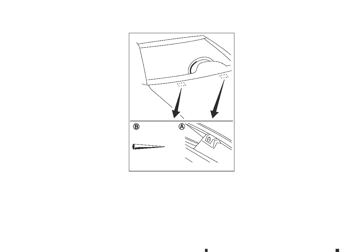
SDI2693Z
Be careful not to clog the washer nozzle
A . This
may cause improper windscreen washer operation.
If the nozzle is clogged, remove any objects with a
needle or small pin
B .Be careful not to damage the
nozzle.
8-16
Maintenance and do-it-yourself
VARIABLE VOLTAGE CONTROL
SYSTEM (where fitted)
The variable voltage control system measures the
amount of electrical discharge from the battery and
controls voltage generated by the alternator.
CAUTION
• Do not ground accessories directly to the bat-
tery terminal. Doing so will bypass the vari-
able voltage control system and the vehicle
battery may not charge completely.
• Use electrical accessories with the engine run-
ning to avoid discharging the vehicle battery.
SDI2048Z
Replacing
Replace the wiper blades if they are worn.
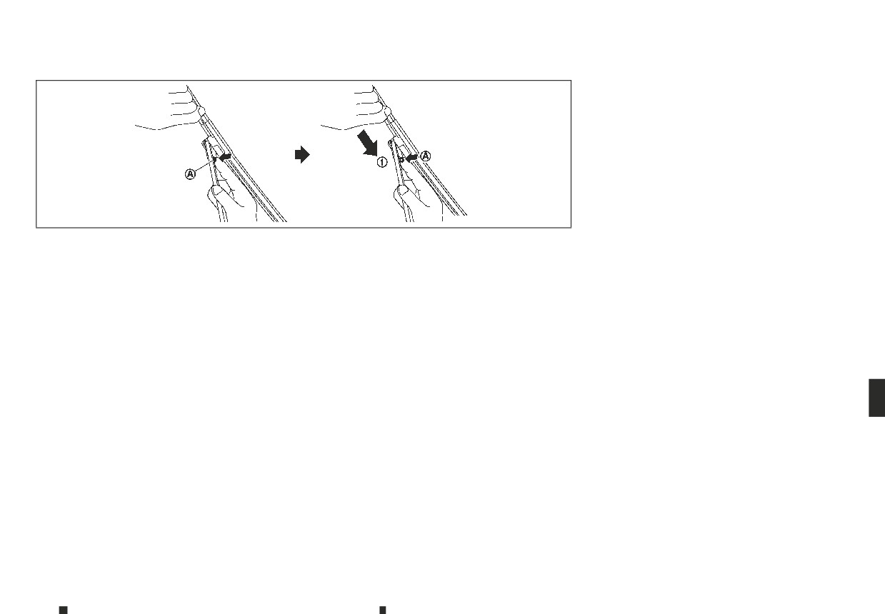
1. Pull the wiper arm.
2. Push and hold the release tab
A , and then move
the wiper blade down ➀ the wiper arm to re-
move.
3. Remove the wiper blade.
4. Insert the new wiper blade onto the wiper arm
until it clicks into place.
CAUTION
• After wiper blade replacement, return the
wiper arm to its original position. Otherwise
the wiper arm or the engine bonnet may be
scratched and may cause damage.
• Worn windscreen wiper blades can damage
the windscreen and impair driver vision.
Maintenance and do-it-yourself
8-17
FUSES
ENGINE COMPARTMENT
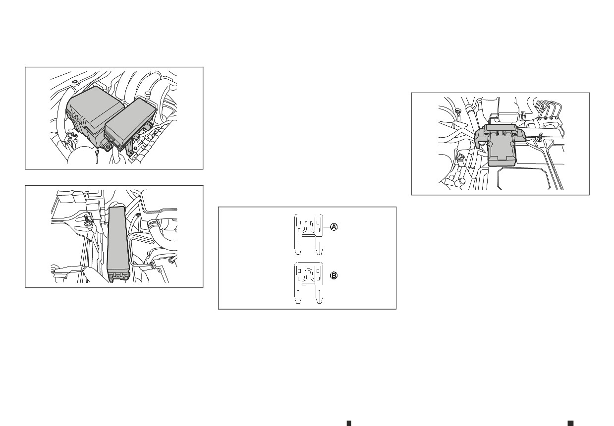
The location and the amperage rating of fuses are
If the new fuse also opens, after installing, have
shown on the underside of the fuse box lid.
the electrical system checked, and if necessary
repaired, by an approved dealer or qualified work-
The number of fuses may vary depending on the
shop.
features equipped to the vehicle.
If any electrical equipment does not operate, check
for an open fuse.
1. Be sure the ignition switch is in the OFF or LOCK
position.
2. Be sure the headlight switch is in the OFF posi-
tion.
NDI1692
3. Open the engine bonnet.
4. Remove the fuse/fusible link cover by pushing
the tab.
NDI1693
5. Locate the fuse which needs to be replaced.
Fusible links
If any electrical equipment does not operate and
the fuses are in good condition, check the fusible
links. If any of these fusible links are melted, replace
only with genuine replacement parts.
NDI1694
CAUTION
SDI1753Z
Never use a fuse of a higher or lower amperage
rating than that specified on the fuse box cover.
6. Remove the fuse using the fuse puller located in
This could damage the electrical system or cause
the passenger compartment fuse box.
a fire.
7. If the fuse is open
A , replace it with a new fuse
Never attempt to use other material (wire, alu-
B.
minium foil. etc.) in place of a fuse. This could
damage the electrical system or cause a fire.
8-18
Maintenance and do-it-yourself
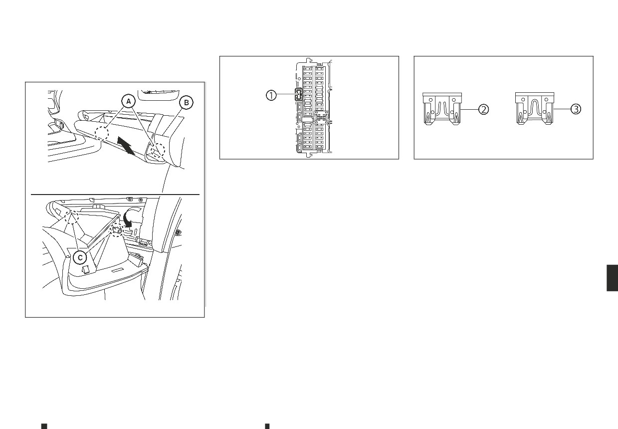
PASSENGER COMPARTMENT
Main fuse box
NDI1689
NDI1688
1. Be sure the ignition switch is in the OFF position.
8. If the fuse is open ➁, replace it with a new fuse
2. Be sure the headlight switch is in the OFF posi-
➂.
tion.
9. Install the glove box following removal steps in
opposite sequence.
3. Open the glove box.
If the new fuse also opens, after installing, have the
4. Hold the glove box lid and pull it up to release the
electrical system checked, and if necessary repaired,
hinges
A located on the underside of the glove
by an approved dealer or qualified workshop.
box. As a reference, align the glove box lid with
corner
B.
5. Carefully release the left and right stoppers
C
and remove the glove box.
6. Locate the fuse that needs to be replaced.
7. Remove the fuse using the fuse puller ➀.
NDI1686
Maintenance and do-it-yourself
8-19
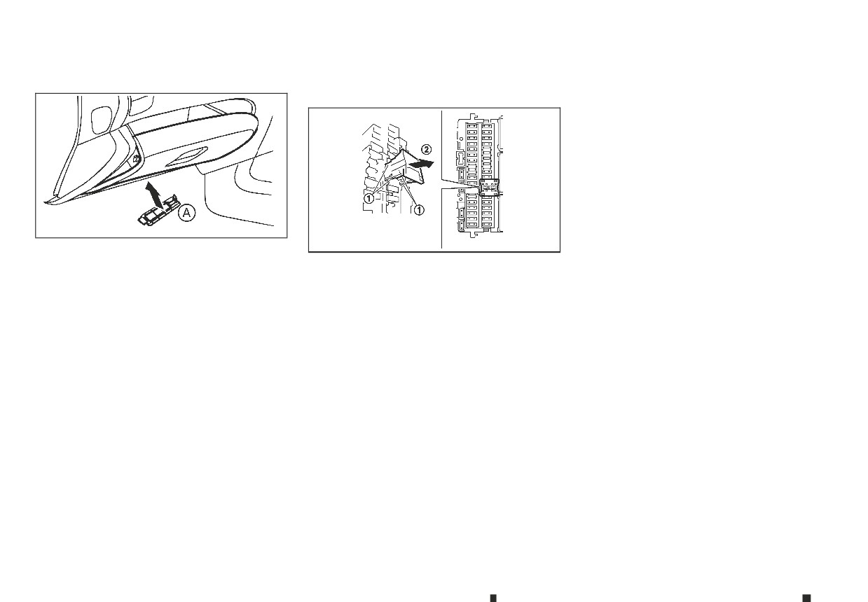
Additional fuse box
Extended storage fuse switch
How to remove the extended storage fuse
switch:
(where fitted)
1.
To remove the extended storage fuse switch, be
sure the ignition switch is in the OFF or LOCK po-
sition.
2.
Be sure the headlight switch is in the OFF posi-
tion.
3.
Remove the fuse box cover.
4.
Pinch the locking tabs ➀ found on each side of
the storage fuse switch.
NTI386
5.
Pull the extended storage fuse switch straight
JVM0462XZ
out from the fuse box ➁.
1.
Be sure the ignition switch is in the OFF position.
2.
Be sure the headlight switch is in the OFF posi-
To reduce battery drain, the extended storage fuse
tion.
switch comes from the factory switched off. Prior to
delivery of your vehicle, the switch is pushed in
3.
Remove the fuse box cover
A from beneath the
(switched on) and should always remain on.
glove box.
If the extended storage fuse switch is not pushed in
4.
Locate the fuse that needs to be replaced.
(switched on), the [Shipping Mode On Push Storage
5.
Remove the fuse using the fuse puller located in
Fuse] warning may appear in the vehicle informa-
the main fuse box.
tion display. See “Indicators for operation” in the
6.
If the fuse is open, replace it with a new fuse.
“2. Instruments and controls” section.
7. Install the fuse box cover.
If any electrical equipment does not operate, re-
move the extended storage fuse switch and check
If the new fuse also opens, after installing, have the
for an open fuse.
electrical system checked, and if necessary repaired,
by an approved dealer or qualified workshop.
NOTE
If the extended storage fuse switch malfunctions
or if the fuse is open, it is not necessary to replace
the switch. In this case, remove the extended stor-
age fuse switch and replace it with a new fuse of
the same rating.
8-20
Maintenance and do-it-yourself
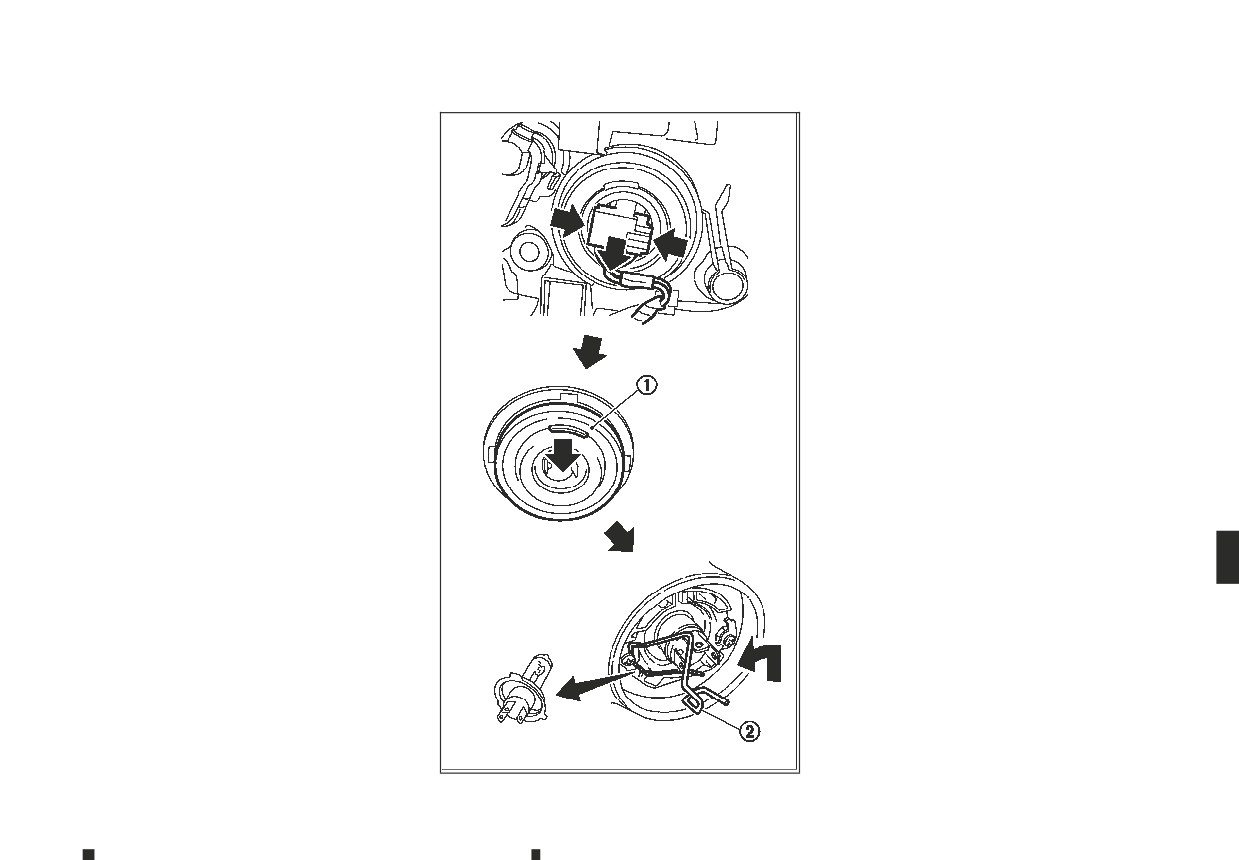
LIGHTS
HEADLIGHTS
Replacing halogen headlight bulb
Fog may temporarily form inside the lens of the ex-
The halogen headlight is a semi-sealed beam type
terior lights in the rain or in a car wash. A tempera-
which uses replaceable headlight (halogen) bulbs.
ture difference between the inside and the outside
They can be replaced from inside the engine com-
of the lens causes the fog. This is not a malfunction.
partment without removing the headlight assem-
If large drops of water collect inside the lens, con-
bly.
tact an approved dealer or qualified workshop.
CAUTION
Replacing LED headlight
High-pressure halogen gas is sealed inside the
bulb. The bulb may break if the glass envelope is
If replacement is
required, contact
an approved
scratched or the bulb is dropped.
dealer or qualified workshop.
1.
Disconnect the battery negative cable.
2.
Disconnect the electrical connector from the
rear end of the bulb.
3.
Pull off the rubber cap ➀.
4.
Push and turn the retaining pin ➁ to loosen it.
5.
Remove the headlight bulb. Do not shake or
rotate the bulb when removing it.
6.
Install the new bulb in the reverse order of
removal.
CAUTION
• When handling the bulb, do not touch the glass
envelope.
• Use the same number and wattage as origi-
nally installed:
Halogen headlight model
High/low beam bulb: 60W/55W (H4)
• Do not leave the bulb out of the headlight re-
flector for a long period of time as dust, mois-
ture and smoke may enter the headlight body
and affect the performance of the headlight.
JVM0470XZ
Maintenance and do-it-yourself
8-21
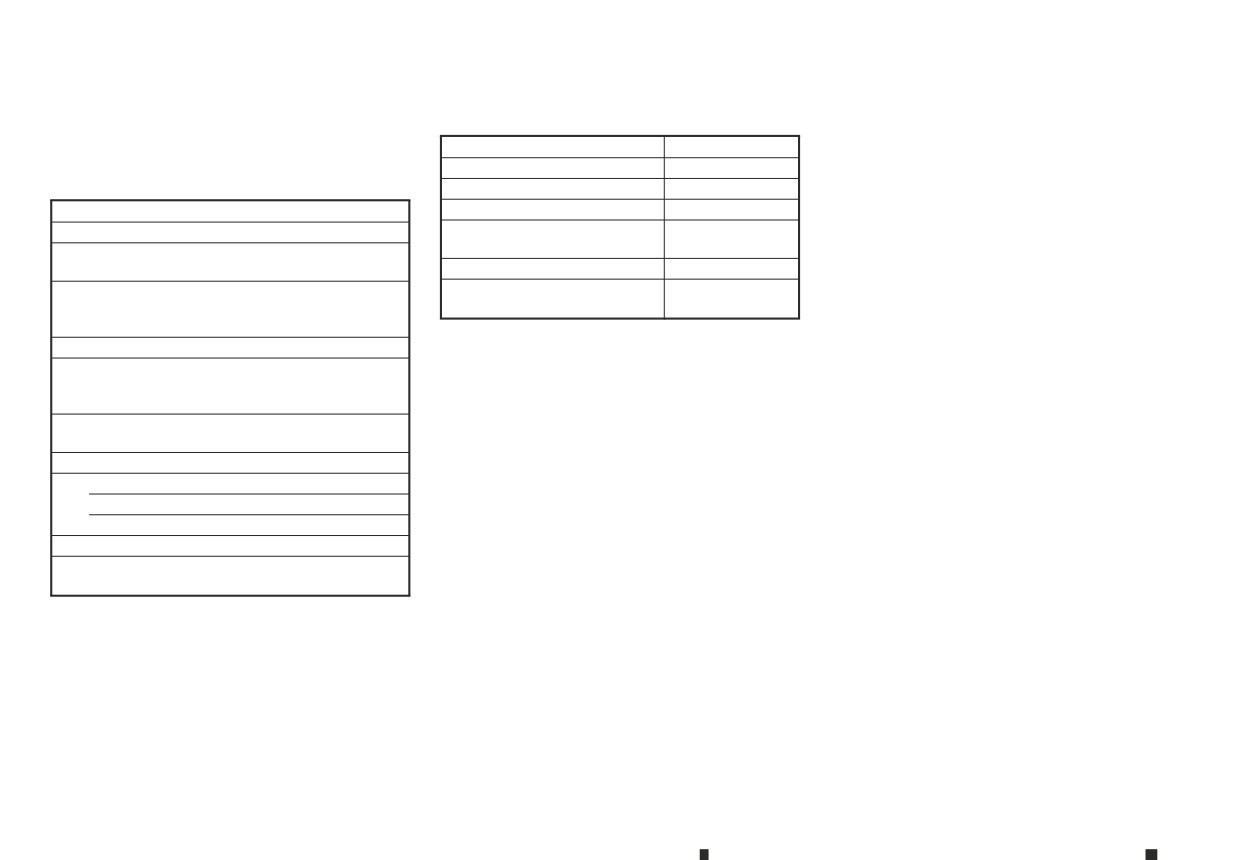
Aiming adjustment is not necessary if only the bulbs
INTERIOR LIGHTS
are replaced. When aiming adjustment is necessary,
Item
Wattage (W)
contact an approved dealer or qualified workshop.
Map light (LED type)*
LED
EXTERIOR LIGHTS
Map light (bulb type)
5
Item
Wattage (W)
Room light (where fitted)
8
Front turn signal
21
Rear personal light (where
LED
fitted)
Clearance light (Halogen
5
headlight models)
Step light (where fitted)
3.4
Clearance light and daytime
Vanity mirror light (where fit-
1.8
running light (LED headlight
LED
ted)
models)*
*:
See an approved dealer or qualified workshop
Front fog light (where fitted)
55
for replacement.
Daytime running light (where
fitted for halogen headlight
19
models)
Side turn signal light (on the
5
front wing) (where fitted)
Rear combination light
Turn signal
21
Stop/tail
21/5
Reverse
21
Number plate light
5
High-mounted stop light
LED
(where fitted)*
*:
See an approved dealer or qualified workshop
for replacement.
8-22
Maintenance and do-it-yourself
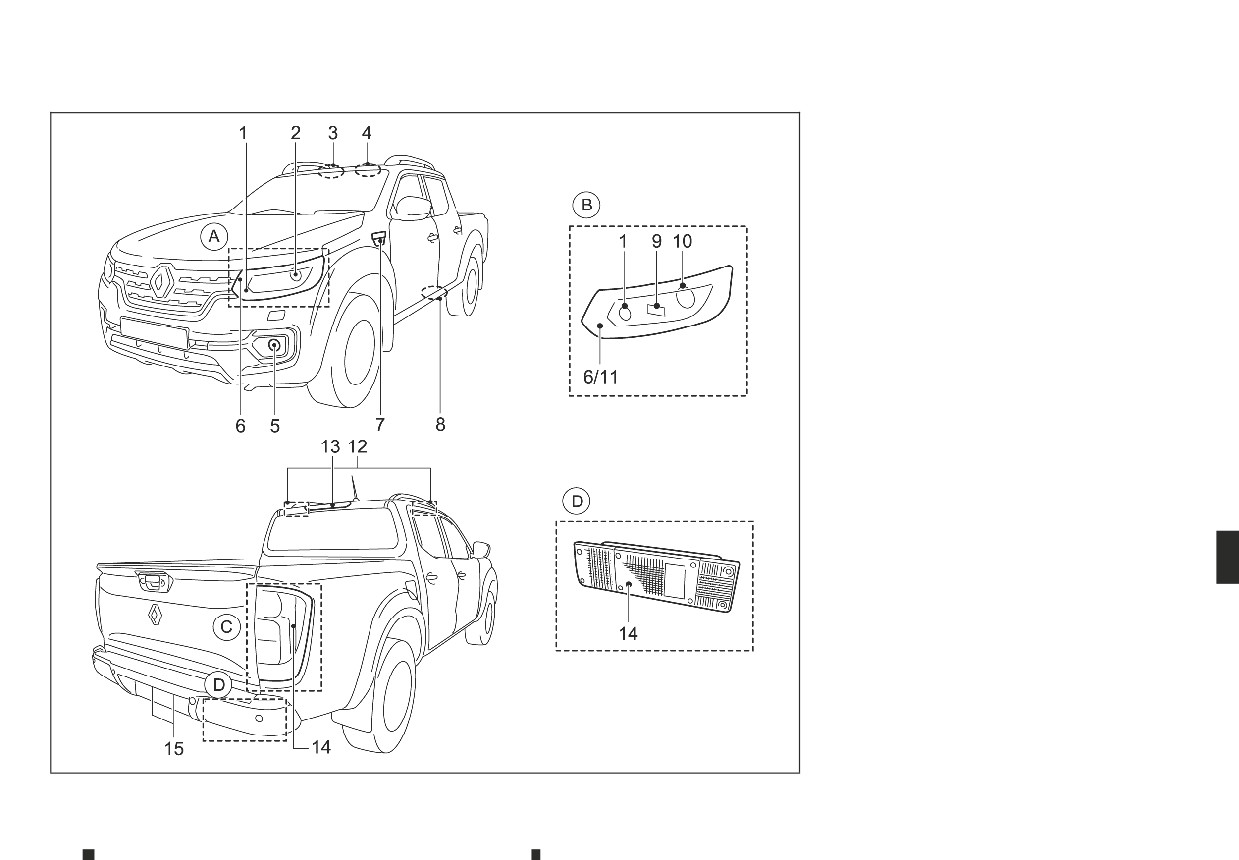
LIGHT LOCATIONS
1.
Front turn signal light
2.
Headlight (halogen type)
3.
Map light
4.
Room light (where fitted)
5.
Front fog light (where fitted) or Daytime run-
ning light (where fitted for halogen headlight
model)
6.
Clearance light
7.
Side turn signal light (where fitted)
8.
Step light (where fitted)
9.
Headlight (high beam) (LED type)
10.
Headlight (low beam) (LED type)
11.
Daytime running light (LED type)
12.
Rear personal light (where fitted)
13.
High-mounted stop light (where fitted)
14.
Rear combination light (Turn signal/Stop/Tail/
Reverse)
15.
Number plate light
A : Halogen headlight model
B : LED headlight model
C : Models with cargo bed
D : Models without cargo bed
NDI1679
Maintenance and do-it-yourself
8-23
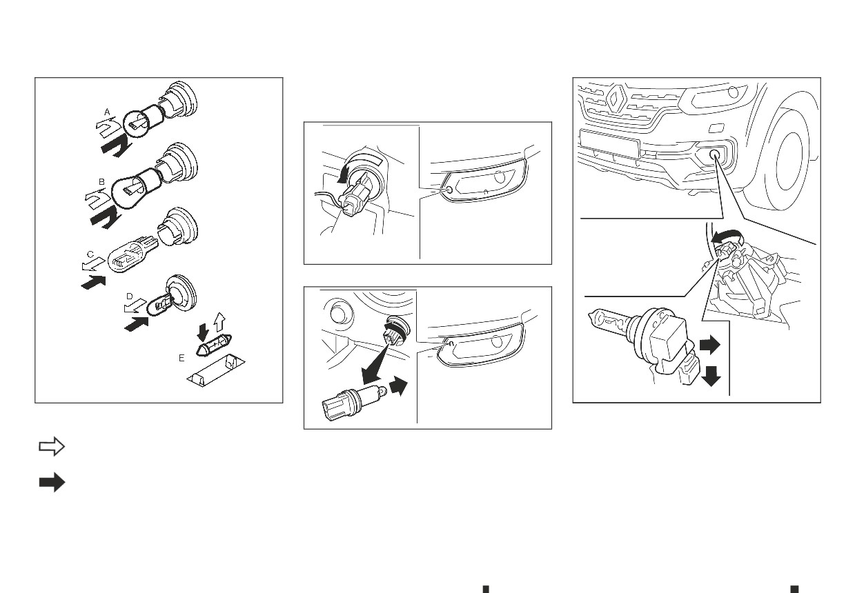
Replacement procedures
All other lights are either type A, B, C, D or E. When
replacing a bulb, first remove the lens and/or cover.
NDI1681
Front turn signal light
SDI2306
NDI1682
Front fog light (where fitted) or daytime running light
(where fitted)
NDI1680
Clearance light (bulb type)
m:REMOVE
INSTALL
m:
8-24
Maintenance and do-it-yourself
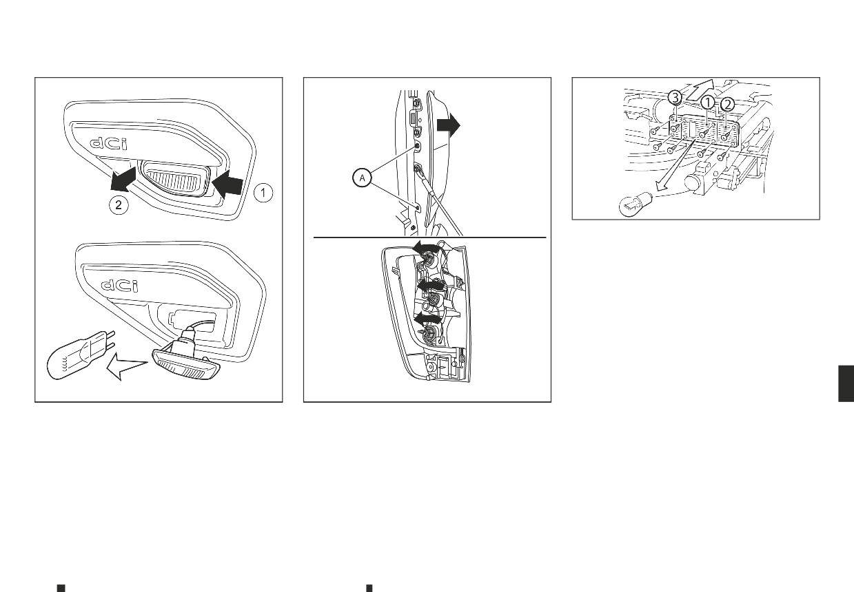
NDI1690
Rear combination light (turn signal, stop and reverse)
(models without cargo bed)
➀: Stop/tail light
➁: Turn signal light
➂: Reverse light
NDI1683
NDI1691
Side turn signal light (on the front wing) (where fitted)
Rear combination light (turn signal, stop and reverse)
(models with cargo bed)
1. Remove two screws
A and remove rear combi-
nation light from vehicle.
2. Rotate bulb socket and remove from rear combi-
nation light.
3. Replace the necessary bulbs.
Maintenance and do-it-yourself
8-25
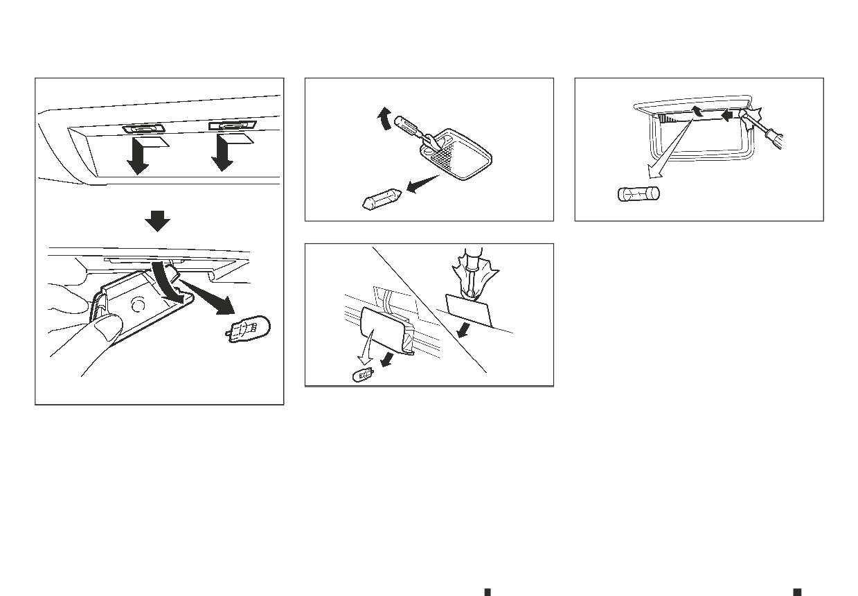
SDI1845Z
SDI1839Z
Room light (where fitted)
Vanity mirror light (where fitted)
JVM0553XZ
Step light (where fitted)
JVM0464XZ
Number plate light
8-26
Maintenance and do-it-yourself