Renault Kangoo VAN Z.E. (2012 year). Instruction - part 5
1.66
DISPLAYS AND INDICATORS
(2/3)
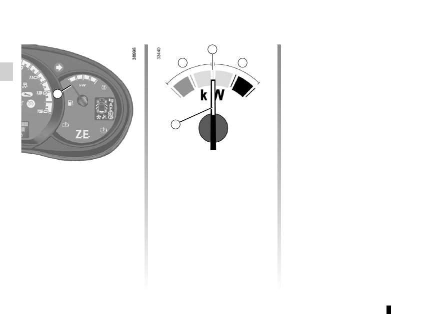
Charge meter 6
Please refer to the information on the
“Charge meter” in Section 2.
The presence and operation of the display and indicators DEPENDS ON THE LEVEL OF EQUIPMENT AND THE COUNTRY.
A
B
C
6
“Energy recovery” usage zone A
The needle tells you that the vehicle is
generating energy and the traction bat-
tery is being recharged (under braking
or going downhill).
“Neutral” position B
The needle tells you that you are at nil
consumption (the vehicle is at a stand-
still without consuming energy).
“Consumption” usage zone C
The needle tells you the energy con-
sumption (vehicle moving on a flat sur-
face, for example).
6