Dacia Pick-Up 1304/1305/1307. Manual - part 94
37
MECHANICAL ELEMENTS CONTROLS
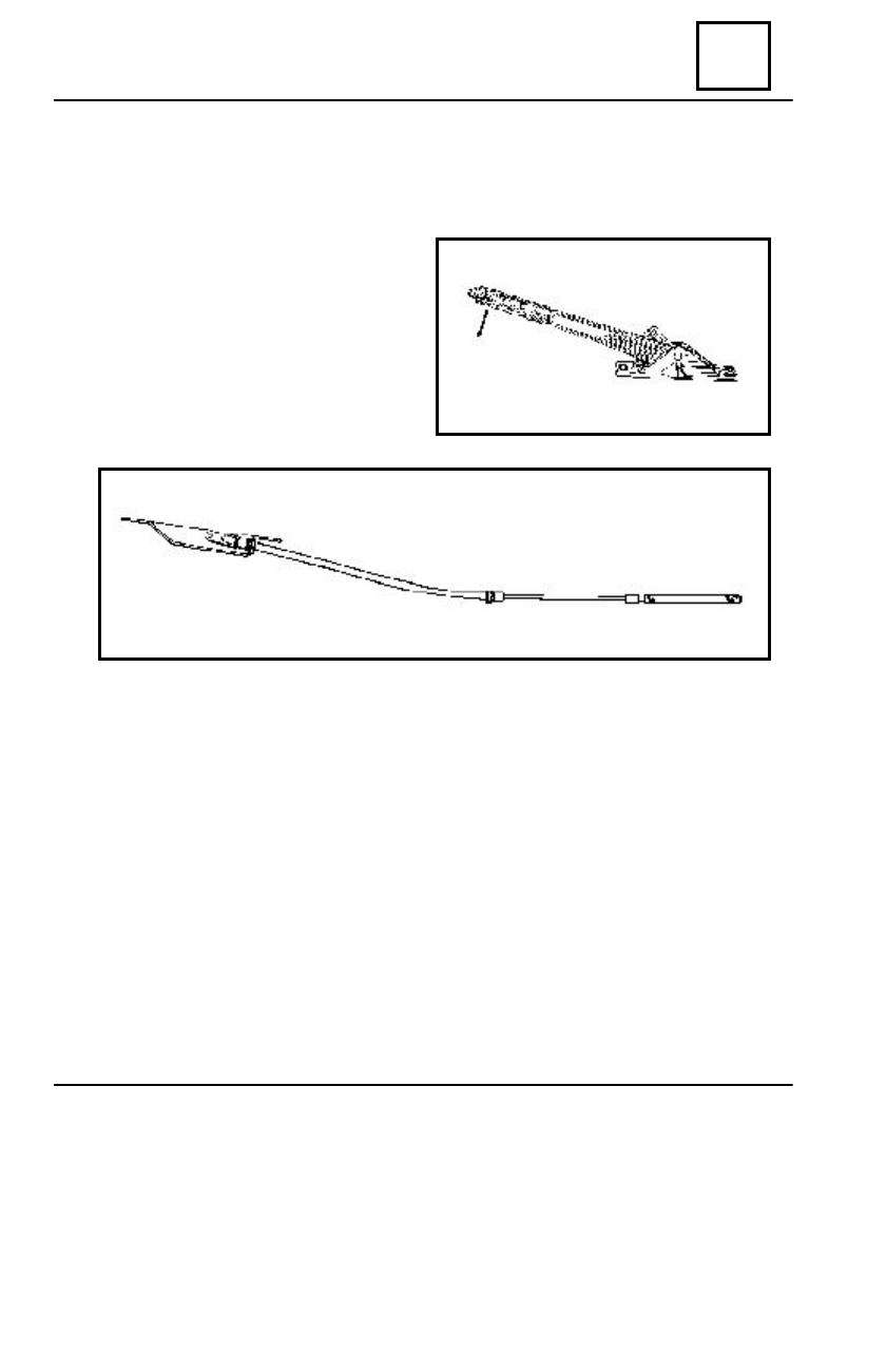
HANDBRAKE PRIMARY AND SECONDARY CABLE
THE HAND BRAKE SECONDARY CABLE REPLACEMENT
D
ISMO UNTING
Dismount the hand brake lever.
Disconnect the primary cable from the
rocking joint.
Dismount the stop sheath of the primary
cable.
R
EMO UNTING
Place a sealant material layer between the floor and the primary cable case.
Mount the primary cable.
Mount the stop sheath.
Mount the hand brake lever.
Adjust the hand brake.
37 - 11