Renault Scenic 3 Chassis. Manual - part 25


  Index      Renault     Renault Scenic 3 Chassis - Manual


Search            


Content   ..  23  24  25  26   ..


Renault Scenic 3 Chassis. Manual - part 25


36B

-

5

POWER ASSISTED STEERING

Steering column

36B

These operations do not require a lift.

REMOVAL

Disconnect the battery, starting with the negative ter-
minal.

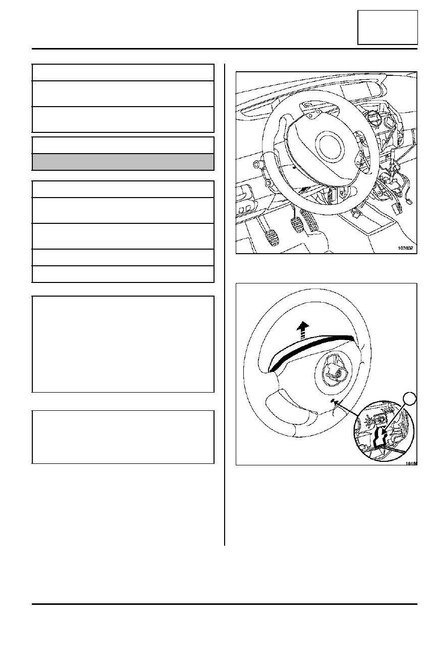
Move the steering column to the low position and pull
it out as far as possible.

Remove the lower casing bolts.

Insert a screwdriver in the aperture behind the stee-
ring wheel.

Unlock the system (9).

Remove the driver's frontal air bag.

Special tooling required

Ms. 1373

Philips radio removal
tool

Ms. 1639

Tool for removing radio
- CD player

Equipment required

Diagnostic tool

Tightening torques

m

steering column moun-
ting nuts

2.1 daNm

steering column univer-
sal joint bolt

2.4 daNm

casing bolts

0.2 daNm

steering wheel bolt

4.4 daNm

IMPORTANT

Before carrying out any work on a safety system
component, lock the air bag computer using the
Diagnostic tool (Section Electrical equipment).
When the function is activated all the trigger lines
are inhibited, and the air bag warning light on the
instrument panel will be lit continuously (when igni-
tion on). 

NOTE

- In the event of problems likely to be caused by a

faulty computer, (see Technical Note 3700A).

103832

18455

9

36B

-

6

POWER ASSISTED STEERING

Steering column

36B

Remove the air bag connectors.

Straighten the wheels.

Disconnect the connectors in the steering wheel.

Remove:

- the steering wheel bolt,

- the steering wheel.

Unclip the upper casing.

Unclip the lower casing.

103813

103799

103800

103801

36B

-

7

POWER ASSISTED STEERING

Steering column

36B

Disconnect the rotary switch connectors.

Undo the rotary switch bolt (10).

Unclip the rotary switch.

Remove the rotary switch.

Unclip the « gear lever gaiter - knob » assembly.

103802

10

103598

103600

36B

-

8

POWER ASSISTED STEERING

Steering column

36B

Unclip the gear lever upper trim.

Disconnect:

- the hazard warning lights switch connector,

- the cigarette lighter connector,

- the voice synthesiser speaker connector.

Remove the gear lever lower trim mountings.

Remove:

- the gear lever lower trim,

- the radio using tool (Ms. 1373) and tool (Ms. 1639),

- the air conditioning control panel fascia. 

Unclip:

- the glovebox (11),

- the beam adjustment control (12) from the rear

(Section Electrical equipment).

Disconnect the beam adjustment control connectors.

103601

103603

103604

103166

12

11


Content   ..  23  24  25  26   ..