Renault Scenic 3 Chassis. Manual - part 22


  Index      Renault     Renault Scenic 3 Chassis - Manual


Search            


Content   ..  20  21  22  23   ..


Renault Scenic 3 Chassis. Manual - part 22


35B

-

1

TYRE PRESSURE MONITOR

Description

35B

This system continuously monitors the pressure status
of the vehicle's four tyres and any system malfunctions.

The spare wheel is not monitored.

The system warns the driver in the event of:

- overinflation,

- under-inflation,

- puncture,

- tyre inflation pressure inappropriate for the vehicle

speed,

- slow puncture between left-hand and right-hand tyres,

- left - right imbalance when starting,

- sensor failure.

The system corrects the pressures measured against
the coldest tyre. The corrected pressure is used to de-
tect leaks and left - right imbalance.

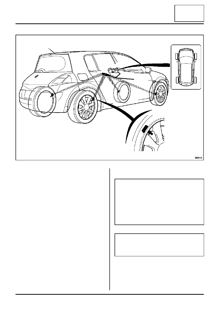
The system comprises:

- four pressure sensors built into the valves (one per

wheel); they transmit a radio frequency signal,

- the UCH, which collects, decodes and processes si-

gnals from the sensors, then determines which mes-
sage to display,

- a display built into the instrument panel.

102413

Note:

Each sensor is identified by a coloured marking 
round the valve:

- green = front left,

- yellow = front right,

- red = rear left,

- black = rear right.

WARNING

Be sure to follow the colour coding, so that the sys-
tem displays the signals correctly. A unique code
enables the UCH to recognise each sensor.

35B

-

2

TYRE PRESSURE MONITOR

Pressure sensor: Operation

35B

The pressure sensor comprises:

- a conventional valve,

- a pressure sensor,

- a temperature sensor,

- an acceleration sensor,

- a specific radiofrequency transmitter,

- a non-removable battery.

OPERATION

The sensors (supplied by a built-in battery) regularly
measure the internal pressure, temperature and acce-
leration of the tyres. They transmit this information and
their code to the receiver (built into the UCH) via radio.

Programming of sensors in the UCH

If replacing valves, program the four sensors using the
Diagnostic tool.

Do not swap the wheels if they have been removed.

When replacing the UCH, program the valves and the
recommended tyre pressures using the Diagnostic to-
ol
.

If you are disabling the tyre monitoring system function,
use the Diagnostic tool to select configuration CF002
« without SSPP »

If you are adding the tyre monitoring system function to
a vehicle not originally fitted with the function, carry out
all of the programming referred to above. Using the
Diagnostic tool, select configuration CF001 « with
SSPP »
 on the UCH and the instrument panel.

Equipment required

Diagnostic tool

102415

Note:

Each sensor is identified by a coloured marking 
round the valve:

- green = front left,

- yellow = front right,

- red = rear left,

- black = rear right.

WARNING

It is essential to follow the colour coding in order to
enable the system to display the signals correctly.
Each sensor has its own unique computer code.

Note:

A second set of two or four wheel sensors can be
identified by the UCH. It is important to keep the
colours in their correct positions.

Note:

In order that the UCH can recognise two or four
additional wheels fitted with sensors, it must be pro-
grammed when the wheels are first fitted. The sys-
tem subsequently automatically recognises the
wheel set which is fitted to the vehicle.

35B

-

3

TYRE PRESSURE MONITOR

Pressure sensor: Repair

35B

REPLACEMENT

The following parts must be replaced:

- the seal (1),

- the mechanism (2),

- the cap (3).

If necessary replace:

- the retaining nut (4),

- the coloured marker (5).

Position the sensor in the valve opening, checking
that the seal is attached all around the edge of the
opening.

Tighten to torque the tyre monitoring system sen-
sor retaining nut  (0.8 daNm)
.

Tightening torques

m

tyre monitoring system
sensor retaining nut 

0.8 daNm

107305

1

2

3

4

5

102242

WARNING

Make sure that the sensor is correct positioned 
on the wheel rim: 

- figure 1 = incorrect refit,

- figure 2 = correct refit.

Note:

After using a tyre repair aerosol, remove the pro-
duct residue from the valve with a dry cloth or air
gun before refitting it on the wheel rim.

2

1

35B

-

4

TYRE PRESSURE MONITOR

Tyres: Replacement

35B

REMOVAL

I - DETACHING THE TYRE BEAD FROM THE 
OUTSIDE OF THE TYRE

Begin on the opposite side to the valve when deta-
ching the tyre bead from the wheel rim.

II - DETACHING THE TYRE BEAD FROM THE 
INSIDE OF THE TYRE

III - REMOVING THE OUTER TYRE BEAD

Position the tyre lever approximately 15 cm from the
valve. 

Remove the tyre bead, finishing at the valve.

IV - REMOVING THE INNER TYRE BEAD

The method is the same as for removing the outer
tyre bead (previous paragraph).

REFITTING

Soap the tyre bead properly.

Insert the lower tyre bead at approximately 15 cm af-
ter the valve.

Finish fitting the tyre at the valve.

Fit the outer bead following the same method as for
the lower tyre bead.

Inflate the tyre to the recommended pressure.

18884

WARNING

Make sure that the tyre bead does not pull on the
sensor at any point.

WARNING

- Detaching the tyre bead from the inside does

not present any particular difficulties.

- Make sure that the tyre bead does not pull on

the sensor at any point.

18885

WARNING

Make sure that the tyre bead does not pull on the
sensor at any point.

WARNING

Make sure that the tyre bead does not pull on the
sensor at any point.


Content   ..  20  21  22  23   ..