Chrysler Cirrus, Dodge Stratus, Plymouth Breeze Haynes. Manual - part 21
5-8
Chapter 5 Engine electrical systems
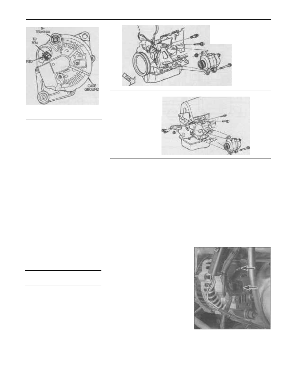
11.8a Alternator mounting details
- 2.0L four-cylinder engine
11.8b Alternator
mounting details - 2.4L
four-cylinder engine
11.6 Alternator electrical connections -
four-cylinder engines
resistance should be 9,000 to 11,000 ohms. If
the resistance is out of tolerance, replace the
sensor.
3
Using a voltmeter, check the battery
voltage with the engine off. It should be
approximately 12 volts.
4
Start the engine and check the battery
voltage again. If the system is operating
properly, the voltage should increase to a
value between 13 to 15 volts.
5
If the indicated voltage reading is less or
more than the specified charging voltage,
have the PCM diagnosed at a dealer service
department or other qualified repair shop.
The voltage regulator on these models is
contained within the PCM and it cannot be
removed or serviced in any way.
6
Due to the special equipment necessary
to test the PCM and alternator, it is recom-
mended that if a fault is suspected, the vehi-
cle be taken to a dealer service department
or other qualified repair shop with the proper
equipment. Because of this, the home
mechanic should limit maintenance to check-
ing connections and the inspection and
replacement of the alternator itself. As a gen-
eral rule, when the battery is in good condi-
tion and all electrical connections are clean
and tight, if the charging voltage is low, the
alternator is faulty. If the charging voltage is
high, the voltage regulator is the problem.
11
Alternator - removal and
installation
General information
1
If you are replacing the alternator, take
the old one with you when purchasing a
replacement unit. Make sure the new/rebuilt
unit looks identical to the old alternator. Look
at the terminals - they should be the same in
number, size and location as the terminals on
the old alternator. Finally, look at the identifi-
cation numbers - they will be stamped into
the housing or printed on a tag attached to
the housing. Make sure the numbers are the
same on both the old and new alternators.
2
Many new/rebuilt alternators do not
have a pulley installed, so you may have to
switch the pulley from the old unit to the
new/rebuilt one. When buying an alternator,
find out the shop's policy regarding pulleys;
some shops will perform this service free of
charge.
Four-cylinder engines
Removal
Refer to illustrations 11.6, 11.8a and 11.8b
3
Disconnect the negative battery cable
from the ground stud on the left shock tower
(see Section 1).
4
On 1995 to 1997 models with 2.4L
engines equipped with anti-lock brakes, dis-
connect the electrical connector and remove
the two lower plate mounting bolts securing
the Controller Anti-lock Brakes (CAB) and
withdraw it from the vehicle (see Chapter 9).
5
On 2.4L engines, remove the engine
coolant reservoir (see Chapter 3).
6
Disconnect the electrical connector and
B+ cable from the alternator (see illustra-
tion).
7
Loosen the drivebelt adjustment bolts
and nut, then detach the alternator drivebelt
(see Chapter 1).
8
Remove the pivot bolt and spacer (see
illustrations).
9
While supporting the alternator, remove
the T-bolt, adjustment nut and bolt, then sep-
arate the alternator from the bracket. Maneu-
ver it toward the passenger side of the vehi-
cle and remove it from the engine compart-
ment. Note: On 2.4L engines equipped with
air conditioning, slide the alternator under the
air conditioning lines.
Installation
10 Installation is the reverse of removal.
11
After the alternator is installed, adjust
the drivebelt tension (see Chapter 1).
12
Check the charging voltage to verify
proper operation of the alternator (see Sec-
tion 10).
V6 engine
Removal
Refer to illustrations 11.14, 11.16 and 11.18
13
Disconnect the negative battery cable
from the ground stud on the left shock tower
(see Section 1).
14
Disconnect the electrical connector and
B+ cable from the alternator (see illustra-
tion).
11.14 Alternator electrical connections
(arrows) - V6 engine