Chrysler Cirrus, Dodge Stratus, Plymouth Breeze Haynes. Manual - part 16
2C-26
Chapter 2 Part C General engine overhaul procedures
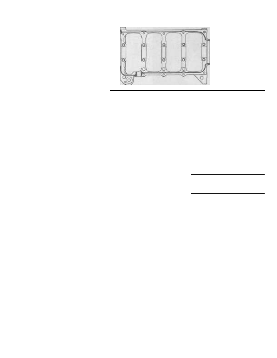
25.21 On four-cylinder
engines, apply a 1/16-inch
bead of anaerobic sealer
( Mopar Torque Cure Gasket
Maker, or equivalent) to the
engine block as shown
the Plastigage envelope to determine the
main bearing oil clearance (see illustration).
Check the tolerance listed in this Chapter's
Specifications to make sure it's acceptable.
16 If the clearance is not as specified, the
bearing inserts may be the wrong size (which
means different ones will be required). Before
deciding if different inserts are needed, make
sure that no dirt or oil was between the bear-
ing inserts and the cap assembly or block
when the clearance was measured. If the
Plastigage was wider at one end than the
other, the crankshaft journal may be tapered
(refer to Section 21). If the clearance still
exceeds the limit specified, the bearing
insert(s) will have to be replaced with an
undersize bearing insert(s). Caution: When
installing a new crankshaft always install a
standard bearing insert set.
17
Carefully scrape all traces of the Plasti-
gage material off the main bearing journals
and/or the bearing insert faces. Be sure to
remove all residue from the oil holes. Use
your fingernail or the edge of a plastic card -
don't nick or scratch the bearing faces.
Final installation
Refer to illustration 25.21
18
Carefully lift the crankshaft out of the
cylinder block.
19
Clean the bearing insert faces in the
cylinder block, then apply a thin, uniform
layer of moly-base grease or engine assem-
bly lube to each of the bearing surfaces. Be
sure to coat the thrust faces as well as the
journal face of the thrust bearing. Caution:
Be sure to install the thrust bearing inserts or
thrust washers (V6 engine) in the No. 3 journal
(see illustrations 25.5a, 25.5b and 25.5c).
20
On 2.0L four-cylinder engines, install a
new oil filter passage 0-ring seal and make
sure the three locating dowels are in place on
the cylinder block. The dowels are necessary
for proper alignment of the main bearing cap
assembly to the cylinder block and
crankshaft.
21
On four-cylinder engines, clean the main
bearing cap assembly-to-cylinder block mat-
ing surfaces. They must be free of any oil
residue. Apply a 1/16-inch bead of anaerobic
sealer (Mopar Torque Cure Gasket Maker, or
equivalent) to the cylinder block as shown
(see illustration). Caution: Use ONLY anaer-
obic sealant meeting the manufacturers spec-
ifications or engine damage may occur.
22
Make sure the crankshaft journals are
clean, then lay the crankshaft back in place in
the cylinder block.
23
Clean the bearing insert faces in the
main bearing cap assembly, then apply the
same lubricant to them. Caution: On four-
cylinder engines, DO NOT get any lubricant
on the main bearing cap assembly-to-cylinder
block mating surfaces as it will inhibit the
sealing ability of the anaerobic sealant.
24
Hold the bearing inserts in place and
install the main bearing cap assembly onto
the crankshaft and cylinder block. On four-
cylinder engines, push the assembly down
until it contacts the locating dowels.
25
Prior to installation, apply clean engine
oil to all bolt threads wiping off any excess,
then install all bolts finger-tight. On 2.0L four-
cylinder engines, install baffle studs in posi-
tions 12, 13 and 16 (see illustration 25.13a).
26
On 2.0L four-cylinder engines, tighten
the main bearing cap assembly as follows
(see illustration 25.13a):
a) Tighten bolts 11, 17 and 20 until the
assembly contacts the engine block.
b) Tighten bolts 1 through 10 in the
sequence shown, in 3 steps to the
torque listed in this Chapter's Specifica-
tions.
c) Tighten bolts 11 through 20 in the
sequence shown to the torque listed in
this Chapter's Specifications.
27
On 2.4L four-cylinder engines, tighten
the main bearing cap assembly as follows
(see illustration 25.13b):
a) Tighten bolts 11, 17 and 20 until the
assembly contacts the engine block.
b) To ensure correct thrust bearing align-
ment, rotate the crankshaft until the No.
4 piston is at TDC.
c) Carefully pry the crankshaft all the way
towards the rear of the block and then
towards the front of the block.
d) Wedge an appropriate tool such as a
block of wood, between the engine
block and the crankshaft counterweight
to hold the crankshaft in the most for-
ward position. DO NOT drive the wedge
between the main bearing cap assembly
and the crankshaft.
e) Tighten bolts 1 through 10 in the
sequence shown, in 3 steps to the
torque listed in this Chapter's Specifica-
tions - except DO NOT tighten the bolts
the additional 1/4-turn.
Remove the wedge and tighten bolts 1
through 10 in the sequence shown, the
additional 1/4-turn.
Tighten bolts 11 through 20 in the
sequence shown to the torque listed in
this Chapter's Specifications.
28
On V6 engines, tighten the main bearing
cap assembly bolts in the sequence shown
(see illustration 25.13c) progressing in three
steps, to the torque listed in this Chapter's
Specifications.
29
After tightening the main bearing cap
assembly, tap the ends of the crankshaft for-
ward and backward with a lead or brass
hammer to seat the main bearing and
crankshaft thrust surfaces.
30
Rotate the crankshaft a number of times
by hand to check for any obvious binding. It
should rotate with a running torque of 50 in-
lbs or less. If the running torque is too high,
correct the problem at this time.
31
Recheck the crankshaft endplay with a
feeler gauge or a dial indicator as described
in Section 16. The endplay should be correct
if the crankshaft thrust faces aren't worn or
damaged and new bearings have been
installed.
32
Refer to the appropriate Part of Chap-
ter 2 and install the new rear main oil seal.
26 Pistons and connecting rods -
installation and rod bearing oil
clearance check
1
Before installing the piston/connecting
rod assemblies, the cylinder walls must be
perfectly clean, the top edge of each cylinder
bore must be chamfered, and the crankshaft
must be in place.
2
Remove the cap from the end of the
number one connecting rod (refer to the
marks made during removal). Remove the
original bearing inserts and wipe the bearing
surfaces of the connecting rod and cap with
a clean, lint-free cloth. They must be kept
spotlessly clean.
Connecting rod bearing oil
clearance check
Refer to illustrations 26.6, 26.11, 26.13 and
26.14 and 26.17
3
Clean the back side of the new upper
bearing insert, then lay it in place in the con-
necting rod. Make sure the tab on the bearing
fits into the recess in the rod. Don't hammer
the bearing insert into place and be very
careful not to nick or gouge the bearing face.
Don't lubricate the bearing at this time.
4
Clean the back side of the other bearing
insert and install it in the rod cap. Again,
make sure the tab on the bearing fits into the
recess in the cap, and don't apply any lubri-
cant. It's critically important that the mating
surfaces of the bearing and connecting rod
f)
g)