Peugeot 405. Manual - part 26


  Главная      Peugeot     Peugeot 405 (1988-1997) - Service And Repair Manual Haynes


поиск по сайту            


содержание   ..  24  25  26  27   ..


Peugeot 405. Manual - part 26


original bearing shells are being used for the
check, ensure that they are refitted in their
original locations. The clearance can be
checked in either of two ways.
One method is to refit the big-end bearing
cap to the connecting rod, ensuring that they
are fitted the correct way around (see
paragraph 20), with the bearing shells in
place. With the cap retaining nuts correctly
tightened, use an internal micrometer or
vernier caliper to measure the internal
diameter of each assembled pair of bearing
shells. If the diameter of each corresponding
crankshaft journal is measured and then
subtracted from the bearing internal diameter,
the result will be the big-end bearing running
clearance.
The second, and more accurate, method is
to use Plastigauge (see Section 18).
Ensure that the bearing shells are correctly
fitted. Place a strand of Plastigauge on each
(cleaned) crankpin journal.
Refit the (clean) piston/connecting rod
assemblies to the crankshaft, and refit the
big-end bearing caps, using the marks made
or noted on removal to ensure that they are
fitted the correct way around.
10 Tighten the bearing cap nuts as described
below in paragraph 21 or 22 (as applicable).
Take care not to disturb the Plastigauge or
rotate the connecting rod during the
tightening sequence.
11 Dismantle the assemblies without rotating
the connecting rods. Use the scale printed on
the Plastigauge envelope to obtain the big-
end bearing running clearance.
12 If the clearance is significantly different
from that expected, the bearing shells may be
the wrong size (or excessively worn, if the
original shells are being re-used). Make sure
that no dirt or oil was trapped between the
bearing shells and the caps or block when the
clearance was measured. If the Plastigauge
was wider at one end than at the other, the
crankshaft journal may be tapered.
13 Note that Peugeot do not specify a
recommended big-end bearing running
clearance. The figure given in the Specifica-
tions is a guide figure, which is typical for this

type of engine. Before condemning the
components concerned, refer to your Peugeot
dealer or engine reconditioning specialist for
further information on the specified running
clearance. Their advice on the best course of
action to be taken can then also be obtained.
14 On completion, carefully scrape away all
traces of the Plastigauge material from the
crankshaft and bearing shells. Use your
fingernail, or some other object which is
unlikely to score the bearing surfaces.

Final piston/connecting rod
refitting

15 Note that the following procedure
assumes that the cylinder liners (where fitted)
are in position in the cylinder block/crankcase
as described in Section 12, and that the
crankshaft and main bearing ladder/caps are
in place (see Section 18).
16 Ensure that the bearing shells are
correctly fitted as described earlier. If new
shells are being fitted, ensure that all traces of
the protective grease are cleaned off using
paraffin. Wipe dry the shells and connecting
rods with a lint-free cloth.
17 Lubricate the cylinder bores, the pistons,
and piston rings, then lay out each
piston/connecting rod assembly in its
respective position.
18 Start with assembly No 1. Make sure that
the piston rings are still spaced as described
in Section 17, then clamp them in position
with a piston ring compressor.
19 Insert the piston/connecting rod assembly
into the top of cylinder/liner No 1. On petrol
engines, ensure that the arrow on the piston
crown is pointing towards the timing belt end
of the engine and on Diesel engines ensure
that the cloverleaf-shaped cut-out on the
piston crown is towards the front (oil filter
side) of the cylinder block. Using a block of
wood or hammer handle against the piston
crown, tap the assembly into the cylinder/liner
until the piston crown is flush with the top of
the cylinder/liner (see illustration).
20 Ensure that the bearing shell is still
correctly installed. Liberally lubricate the
crankpin and both bearing shells. Taking care
not to mark the cylinder/liner bores, pull the

piston/connecting rod assembly down the
bore and onto the crankpin. Refit the big-end
bearing cap, tightening its retaining nuts
finger-tight at first. Note that the faces with
the identification marks must match (which
means that the bearing shell locating tabs
abut each other). 
21 On TU series engines, tighten the bearing
cap retaining nuts evenly and progressively to
the specified torque setting.
22 On XU series engines, tighten the bearing
cap retaining nuts evenly and progressively to
the stage 1 torque setting. Fully slacken both
nuts, then tighten them to the stage 2 torque
setting. Once both nuts have been tightened
to the stage 2 setting, angle-tighten them
through the specified stage 3 angle, using a
socket and extension bar. It is recommended
that an angle-measuring gauge is used during
this stage of the tightening, to ensure
accuracy (see illustrations). If a gauge is not
available, use a dab of white paint to make
alignment marks between the nut and bearing
cap prior to tightening; the marks can then be
used to check that the nut has been rotated
sufficiently during tightening.
23 On all engines, once the bearing cap
retaining nuts have been correctly tightened,
rotate the crankshaft. Check that it turns
freely; some stiffness is to be expected if new
components have been fitted, but there
should be no signs of binding or tight spots.
24 Refit the remaining three piston/
connecting rod assemblies in the same way.
25 Refit the cylinder head and oil pump as
described in Part A or B of this Chapter (as
applicable).

20 Engine 

initial start-up after overhaul

With the engine refitted in the vehicle,
double-check the engine oil and coolant
levels. Make a final check that everything has
been reconnected, and that there are no tools
or rags left in the engine compartment.
Remove the spark plugs. On models with a
distributor, disable the ignition system by

2C•22 Engine removal and overhaul

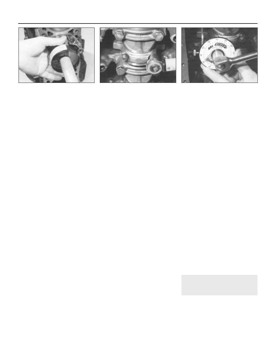
19.19  Tap the piston into the bore using a

hammer handle

19.22b  . . . then through the angle

specified for stage 3

19.22a  On XU series engines, tighten the

big-end bearing cap nuts to the stage 1

specified torque, then fully slacken them

and tighten them to the stage 2 torque . . .

disconnecting the ignition HT coil lead from
the distributor cap, and earthing it on the
cylinder block. Use a jumper lead or similar
wire to make a good connection. On models
with a static (distributorless) ignition system,
disable the ignition system by disconnecting
the LT wiring connector from the ignition HT
coil, referring to Chapter 5B for information.
Turn the engine on the starter until the oil
pressure warning light goes out. Refit the
spark plugs, and reconnect the spark plug
(HT) leads, referring to Chapter 1 for further
information. Reconnect any HT leads or wiring
which was disconnected in paragraph 2.
Start the engine, noting that this may take a

little longer than usual, due to the fuel system
components having been disturbed.
While the engine is idling, check for fuel,
water and oil leaks. Don’t be alarmed if there
are some odd smells and smoke from parts
getting hot and burning off oil deposits. On
16-valve engines, some valvegear noise may
be heard at first; this should disappear as the
oil circulates fully around the engine, and
normal pressure is restored in the hydraulic
tappet mechanism.
Assuming all is well, keep the engine idling
until hot water is felt circulating through the
top hose, then switch off the engine.
Check the ignition timing and the idle 

speed settings, then switch the engine off.
After a few minutes, recheck the oil and
coolant levels as described in Chapter 1, and
top-up as necessary.
If they were tightened as described, there is
no need to re-tighten the cylinder head bolts
once the engine has first run after reassembly.
10 If new pistons, rings or crankshaft
bearings have been fitted, the engine must be
treated as new, and run-in for the first 
500 miles (800 km). Do not operate the engine
at full-throttle, or allow it to labour at low
engine speeds in any gear. It is recommended
that the oil and filter be changed at the end of
this period.

Engine removal and overhaul  2C•23

2C

3

Thermostat

Opening temperatures:

Starts to open:

1360 cc engines  . . . . . . . . . . . . . . . . . . . . . . . . . . . . . . . . . . . . . . .

88°C

1580 cc engines:

All except B2A (XU52C) and BDY (XU5M) engines . . . . . . . . . . .

88°C

B2A (XU52C) and BDY (XU5M) engines  . . . . . . . . . . . . . . . . . . .

82°C

1761 cc engines  . . . . . . . . . . . . . . . . . . . . . . . . . . . . . . . . . . . . . . .

88°C

1905 cc engines:

All except D2H (XU92C), D5A (XU92C) and 
D6D (XU9J2) engines  . . . . . . . . . . . . . . . . . . . . . . . . . . . . . . . . .

88°C

D2H (XU92C), D5A (XU92C) and D6D (XU9J2) engines  . . . . . . .

82°C

1998 cc engines:

RFX (XU10J2C) and RFY (XU10J4) engines  . . . . . . . . . . . . . . . .

89°C

RGZ (XU10J4) engine  . . . . . . . . . . . . . . . . . . . . . . . . . . . . . . . . .

88°C

Fully open:

1360 cc engines  . . . . . . . . . . . . . . . . . . . . . . . . . . . . . . . . . . . . . . .

100°C

1580 cc engines

All except B2A (XU52C), B3B (XU51C) and 
BDY (XU5M engines  . . . . . . . . . . . . . . . . . . . . . . . . . . . . . . . . . .

100°C

B2A (XU52C) engine  . . . . . . . . . . . . . . . . . . . . . . . . . . . . . . . . . .

93°C

B3B (XU51C) engine  . . . . . . . . . . . . . . . . . . . . . . . . . . . . . . . . . .

102°C

BDY (XU5M) engine . . . . . . . . . . . . . . . . . . . . . . . . . . . . . . . . . . .

94°C

1761 cc engines  . . . . . . . . . . . . . . . . . . . . . . . . . . . . . . . . . . . . . . .

100°C

1905 cc engines:

All except D2H (XU92C), D5A (XU92C) and 
D6D (XU9J2) engines  . . . . . . . . . . . . . . . . . . . . . . . . . . . . . . . . .

100°C

D2H (XU92C) and D5A (XU92C) engines  . . . . . . . . . . . . . . . . . .

93°C

D6D (XU9J2) engine  . . . . . . . . . . . . . . . . . . . . . . . . . . . . . . . . . .

94°C

1998 cc engines

RFX (XU10J2C) and RFY (XU10J4) engines  . . . . . . . . . . . . . . . .

101°C

RGZ (XU10J4) engine  . . . . . . . . . . . . . . . . . . . . . . . . . . . . . . . . .

100°C

Torque wrench settings

Nm

lbf ft

Coolant pump housing bolts (aluminium block engine):

Smaller bolts  . . . . . . . . . . . . . . . . . . . . . . . . . . . . . . . . . . . . . . . . . . . .

30

22

Larger bolts . . . . . . . . . . . . . . . . . . . . . . . . . . . . . . . . . . . . . . . . . . . . .

65

48

Coolant pump securing bolts (iron block engine) . . . . . . . . . . . . . . . . . .

15

11

Chapter 3
Cooling, heating and ventilation systems

Air conditioning system - general information and precautions  . . . . .10
Air conditioning system components - removal and refitting . . . . . . .11
Antifreeze mixture  . . . . . . . . . . . . . . . . . . . . . . . . . . . . . .See Chapter 1
Coolant pump - removal and refitting . . . . . . . . . . . . . . . . . . . . . . . . . .7
Coolant level check  . . . . . . . . . . . . . . . . . . . . . . .See “Weekly checks”
Cooling system electrical switches and sensors - 

testing, removal and refitting  . . . . . . . . . . . . . . . . . . . . . . . . . . . . . .6

Cooling system - draining  . . . . . . . . . . . . . . . . . . . . . . . .See Chapter 1
Cooling system - filling  . . . . . . . . . . . . . . . . . . . . . . . . . .See Chapter 1

Cooling system - flushing  . . . . . . . . . . . . . . . . . . . . . . . .See Chapter 1
Cooling system hoses - disconnection and renewal  . . . . . . . . . . . . . .2
Electric cooling fan(s) - testing, removal and refitting  . . . . . . . . . . . . .5
General information and precautions  . . . . . . . . . . . . . . . . . . . . . . . . . .1
Heating and ventilation system - general information  . . . . . . . . . . . . .8
Heater/ventilation components - removal and refitting  . . . . . . . . . . . .9
Pollen filter renewal  . . . . . . . . . . . . . . . . . . . . . . . . . . . . .See Chapter 1
Radiator - removal, inspection and refitting  . . . . . . . . . . . . . . . . . . . . .3
Thermostat - removal, testing and refitting  . . . . . . . . . . . . . . . . . . . . .4

3•1

Easy, suitable for
novice with little
experience

Fairly easy, suitable
for beginner with
some experience

Fairly difficult,
suitable for competent
DIY mechanic

Difficult, suitable for
experienced  DIY
mechanic

Very difficult,
suitable for expert
DIY or  professional

Degrees of difficulty

Specifications

Contents

1

General information and
precautions

General information

The cooling system is of pressurised type,

comprising a coolant pump driven by the
timing belt, an aluminium crossflow radiator
with integral expansion tank, electric cooling
fan(s), a thermostat, heater matrix, and all
associated hoses and switches.

The system functions as follows. Cold

coolant in the bottom of the radiator passes
through the bottom hose to the coolant pump,
where it is pumped around the cylinder block
and head passages, and through the oil
cooler(s) (where fitted). After cooling the
cylinder bores, combustion surfaces and
valve seats, the coolant reaches the
underside of the thermostat, which is initially
closed. The coolant passes through the
heater, and is returned via the cylinder block
to the coolant pump.

When the engine is cold, the coolant

circulates only through the cylinder block,
cylinder head, and heater. When the coolant
reaches a predetermined temperature, the
thermostat opens, and the coolant passes
through the top hose to the radiator. As the
coolant circulates through the radiator, it is
cooled by the inrush of air when the car is in
forward motion. The airflow is supplemented
by the action of the electric cooling fan(s)
when necessary. Upon reaching the bottom of
the radiator, the coolant has now cooled, and
the cycle is repeated.

When the engine is at normal operating

temperature, the coolant expands, and some
of it is displaced into the expansion tank,
incorporated in the side of the radiator.
Coolant collects in the tank, and is returned to
the radiator when the system cools.

On models with automatic transmission, a

proportion of the coolant is recirculated from
the bottom of the radiator through the
transmission fluid cooler mounted on the
transmission. On models fitted with an engine
oil cooler,  the coolant is also passed through
the oil cooler.

The electric cooling fan(s) mounted in front

of the radiator are controlled by a
thermostatic switch. At a predetermined
coolant temperature, the switch/sensor
actuates the fan.

Precautions

2

Cooling system hoses -
disconnection and renewal

2

Note: Refer to the warnings given in Section 1
of this Chapter before proceeding. Hoses
should only be disconnected once the engine
has cooled sufficiently to avoid scalding.
If the checks described in Chapter 1 reveal
a faulty hose, it must be renewed as follows.
First drain the cooling system (see 
Chapter 1). If the coolant is not due for
renewal, it may be re-used, providing it is
collected in a clean container.
To disconnect a hose, proceed as follows,
according to the type of hose connection.

Conventional hose connections -
general instructions

On conventional connections, the clips
used to secure the hoses in position may be
either standard worm-drive clips or
disposable crimped types. The crimped type
of clip is not designed to be re-used and
should be replaced with a worm drive type on
reassembly.
To disconnect a hose, use a screwdriver to
slacken or release the clips, then move them
along the hose, clear of the relevant
inlet/outlet. Carefully work the hose free. The
hoses can be removed with relative ease
when new - on an older car, they may have
stuck.
If a hose proves to be difficult to remove, try
to release it by rotating its ends before
attempting to free it. Gently prise the end of

the hose with a blunt instrument (such as a
flat-bladed screwdriver), but do not apply too
much force, and take care not to damage the
pipe stubs or hoses. Note in particular that the
radiator inlet stub is fragile; do not use
excessive force when attempting to remove
the hose. If all else fails, cut the hose with a
sharp knife, then slit it so that it can be peeled
off in two pieces. Although this may prove
expensive if the hose is otherwise
undamaged, it is preferable to buying a new
radiator. Check first, however, that a new
hose is readily available.
When fitting a hose, first slide the clips onto
the hose, then work the hose into position. If
crimped-type clips were originally fitted, use
standard worm-drive clips when refitting the
hose. If the hose is stiff, use a little soapy
water as a lubricant, or soften the hose by
soaking it in hot water. Do not use oil or
grease, which may attack the rubber.
Work the hose into position, checking that it
is correctly routed, then slide each clip back
along the hose until it passes over the flared
end of the relevant inlet/outlet, before
tightening the clip securely.
Refill the cooling system with reference to
Chapter 1.
10 Check thoroughly for leaks as soon as
possible after disturbing any part of the
cooling system.

Radiator hose(s) - 
bayonet-type connection

Note: A new O-ring should be used when
reconnecting the hose.

Removal

11 On later models, the radiator hoses are
connected to the radiator using a plastic
bayonet-type connection. To disconnect this
type of connector, proceed as follows.
12 Twist the end of the hose (with the
connector) anti-clockwise until the clips on
the connector are clear of the retaining lugs
on the radiator stub, then pull the end of the
hose from the radiator. Recover the O-ring
from the end of the hose connector (see
illustrations)
.

Refitting

13 Fit a new O-ring to the hose connector,
then reconnect the hose using a reversal of

3•2 Cooling, heating and ventilation systems

2.12a  Twist the connector until 

the clips (A) are clear of the lugs (B)

Warning: Do not attempt to
remove the expansion tank filler
cap, or to disturb any part of the
cooling system, while the

engine is hot, as there is a high risk of
scalding. If the expansion tank filler cap
must be removed before the engine and
radiator have fully cooled (even though
this is not recommended), the pressure in
the cooling system must first be relieved.

Cover the cap with a thick layer of cloth,
to avoid scalding, and slowly unscrew the
filler cap until a hissing sound is heard.
When the hissing has stopped, indicating
that the pressure has reduced, slowly
unscrew the filler cap until it can be
removed; if more hissing sounds are
heard, wait until they have stopped before
unscrewing the cap completely. At all
times, keep well away from the filler cap
opening, and protect your hands.

Do not allow antifreeze to come into

contact with your skin, or with the painted
surfaces of the vehicle. Rinse off spills
immediately, with plenty of water. Never
leave antifreeze lying around in an open
container, or in a puddle in the driveway
or on the garage floor. Children and pets
are attracted by its sweet smell, but
antifreeze can be fatal if ingested.

If the engine is hot, the electric cooling

fan may start rotating even if the engine is
not running. Be careful to keep your
hands, hair, and any loose clothing well
clear when working in the engine
compartment.

Refer to Section 10 for precautions to

be observed when working on models
equipped with air conditioning.


содержание   ..  24  25  26  27   ..