Opel Karl (2019 year). Manual - part 4


  Index      Opel     Opel Karl (2019 year) - manual in english


Search            copyright infringement  


Content      ..     2      3      4      5     ..


Opel Karl (2019 year). Manual - part 4


54

Storage

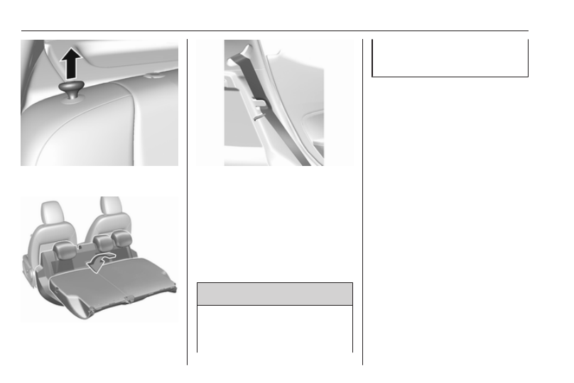
4. Pull the release knob on top of the

rear backrest.

5. Fold down the backrest and insert

the rear seat head restraints into

the pockets.

6. Put the seat belts for the outboard

seats into the belt guides.

7. Adjust the front seats to the

desired position.

To return the backrest to the original

position:

1. Lift the backrest up and pull out

the seat belt from the belt guides.

Push backrest firmly into place.

9 Warning

When folding up, ensure that

backrests are securely engaged in

position before driving. Failure to

do so may result in personal injury

or damage to the load or vehicle in

the event of hard braking or a

collision.

Ensure the seat belts are not

pinched by the latch.

2. Reinstall the rear head restraints.
3. Place the rear part of the seat

cushion in its original position.

Note

Make sure the seat belts are not

twisted or caught under the seat

cushion.

4. Push the front part of the seat

cushion down firmly until it

latches.

The centre rear seat belt may lock

when you raise the backrest. If this

happens, allow the belt to go back all

the way and repeat operation.
If the seat belt is still locked, fold down

the seat cushion and try again.
To return the rear seat cushion, put

the rear part of the seat cushion in its

original position ensuring that the

seat belt buckle straps are not twisted

-------------------------------------------------------------------------------------------------------------------------------------------------------------

Storage

55

or caught under the seat cushion,

then push the front part of the seat

cushion firmly down until it latches.

Caution

When returning rear seat backrest

to the upright position, place the

rear seat belt and buckles

between the rear seat backrest

and one cushion. Make sure the

rear seat belt and buckles do not

get pinched under the rear seat

cushion.
Ensure the seat belts are not

twisted or caught in the seat

backrest and are arranged in their

proper position.

To remove the rear seat cushion,

push the hinges in direction of arrow.

Load compartment cover

Do not place heavy objects on the

cover.

Removing

Lift cover at the rear and push it

upwards at the front.
Remove the cover.

Stowing

When the load compartment is fully

loaded, stow the load compartment

cover on the rear seats or remove

from vehicle.

Fitting

Engage cover in side guides and fold

downwards. Attach retaining straps to

tailgate.

-------------------------------------------------------------------------------------------------------------------------------------------------------------

56

Storage

Rear floor storage cover

Rear floor cover

Lift up rear floor cover to gain access

to the tyre repair kit, vehicle tools and

warning triangle.
On versions with spare wheel, the

spare wheel is located under the rear

floor cover together with the vehicle

tools.
Tools 3 144.

General hint

9 Warning

For safety reasons, stow all parts

in the load compartment in its

position, always drive with a

closed rear floor cover and, if

possible, with folded up rear

backrests.
Otherwise, vehicle occupants

could be injured by objects being

thrown around in the event of

sharp braking, a sudden change in

direction or an accident.

Warning triangle

Vehicles with spare wheel

Stow the warning triangle in the load

compartment.

-------------------------------------------------------------------------------------------------------------------------------------------------------------

Storage

57

Vehicles with tyre repair kit

Stow the warning triangle in the

vehicle tool box below the floor over

in the load compartment.

First aid kit

Stow the first-aid kit in the load

compartment.

Roof rack system

Roof rack

For safety reasons and to avoid

damage to the roof, a vehicle

approved roof rack system is

recommended.
Mount the roof rack to the roof rails

following the installation instructions

delivered with the roof rack.
Remove the roof rack when not in

use.

-------------------------------------------------------------------------------------------------------------------------------------------------------------

58

Storage

Loading information

● Heavy objects in the load

compartment should be placed

against the seat backrests.

Ensure that the backrests are

securely engaged. If objects can

be stacked, heavier objects

should be placed at the bottom.

● Prevent sliding of loose objects

by securing them with straps

attached to the lashing eyes.

● When transporting objects in the

load compartment, the backrests

of the rear seats must not be

angled forward.

● Do not allow the load to protrude

above the upper edge of the

backrests.

● Do not place any objects on the

load compartment cover or the

instrument panel, and do not

cover the sensor on top of the

instrument panel.

● The load must not obstruct the

operation of the pedals, parking

brake and gear selector lever, or

hinder the freedom of movement

of the driver. Do not place any

unsecured objects in the interior.

● Do not drive with an open load

compartment.

9 Warning

Always make sure that the load in

the vehicle is securely stowed.

Otherwise objects can be thrown

around inside the vehicle and

cause personal injury or damage

to the load or vehicle.

● The payload is the difference

between the permitted gross

vehicle weight (see identification

plate 3 168) and the EC kerb

weight.
To calculate the payload, enter

the data for your vehicle in the

weights table at the front of this

manual.
The EC kerb weight includes

weights for the driver (68 kg),

luggage (7 kg) and all fluids (fuel

tank 90% full).

Optional equipment and

accessories increase the kerb

weight.

● Driving with a roof load increases

the sensitivity of the vehicle to

cross-winds and has a

detrimental effect on vehicle

handling due to the vehicle's

higher centre of gravity.

Distribute the load evenly and

secure it properly with retaining

straps. Adjust the tyre pressure

and vehicle speed according to

the load conditions. Check and

retighten the straps frequently.
The permissible roof load for

vehicles with roof railing is 50 kg.

The roof load is the combined

weight of the roof rack and the

load.

-------------------------------------------------------------------------------------------------------------------------------------------------------------

Instruments and controls

59

Instruments and

controls

Controls ....................................... 60

Steering wheel adjustment ........ 60

Steering wheel controls ............. 60

Heated steering wheel ............... 60

Horn ........................................... 61

Windscreen wiper and washer . . 61

Rear window wiper and

washer ...................................... 62

Outside temperature .................. 62

Clock ......................................... 62

Power outlets ............................. 64

Cigarette lighter ......................... 64

Ashtrays .................................... 64

Warning lights, gauges and indi‐

cators ........................................... 64

Instrument cluster ...................... 64

Speedometer ............................. 64

Odometer .................................. 65

Trip odometer ............................ 65

Tachometer ............................... 65

Fuel gauge ................................ 65

Engine coolant temperature

gauge ....................................... 66

Service display .......................... 66

Control indicators ...................... 67

Turn lights .................................. 69

Seat belt reminder ..................... 70

Airbag and belt tensioners ......... 70

Airbag deactivation .................... 70

Charging system ....................... 71

Malfunction indicator light .......... 71

Service vehicle soon ................. 71

Brake and clutch system ........... 71

Operate pedal ............................ 71

Antilock brake system (ABS) ..... 72

Gear shifting .............................. 72

Power steering .......................... 72

Lane departure warning ............ 72

Parking assist ............................ 72

Electronic Stability Control off ... 72

Electronic Stability Control and

Traction Control system ........... 72

Traction Control system off ....... 73

Engine coolant temperature ...... 73

Tyre pressure monitoring

system ...................................... 73

Engine oil pressure .................... 73

Low fuel ..................................... 74

Immobiliser ................................ 74

Reduced engine power ............. 74

Exterior light .............................. 74

High beam ................................. 74

Front fog lights ........................... 74

Rear fog light ............................. 74

Cruise control ............................ 74

Speed limiter ............................. 74

Bonnet open .............................. 74

Door open .................................. 75

Displays ....................................... 75

Driver Information Centre .......... 75

Info Display ................................ 80

Vehicle messages ........................ 81

Warning chimes ......................... 83

Battery voltage .......................... 83

Vehicle personalisation ................ 83
Telematics service ....................... 86

OnStar ....................................... 86

-------------------------------------------------------------------------------------------------------------------------------------------------------------

60

Instruments and controls

Controls

Steering wheel adjustment

Unlock lever, adjust steering wheel,

then engage lever and ensure it is

fully locked.
Do not adjust steering wheel unless

vehicle is stationary and steering

wheel lock has been released.

Steering wheel controls

Cruise control and speed limiter are

operated via the controls on the left

side of the steering wheel.
Infotainment system can be operated

via the controls on the right side of the

steering wheel.
Driver assistance systems 3 117.
Further information is available in the

Infotainment manual.

Heated steering wheel

Activate heating by pressing A.

Activation is indicated by the LED in

the button.

-------------------------------------------------------------------------------------------------------------------------------------------------------------

Instruments and controls

61

The grip areas of the steering wheel

are heated quicker and to a higher

temperature than the other areas.
Heating is operational when the

engine is running and during an

Autostop.
Stop-start system 3 107.

Horn

Press j.

Windscreen wiper and

washer

Windscreen wiper

HI

: fast

LO : slow

E

: interval wiping

OFF : off
For a single wipe when the

windscreen wiper is off, press the

lever down to position 2.
Do not use if the windscreen is frozen.
Switch off in car washes.

Windscreen washer

Pull lever. Washer fluid is sprayed

onto the windscreen and the wiper

wipes a few times.
Washer fluid 3 131

-------------------------------------------------------------------------------------------------------------------------------------------------------------

62

Instruments and controls

Rear window wiper and

washer

Press the rocker switch to activate the

rear window wiper:
upper position : continuous

operation

lower position : intermittent

operation

middle position : off

Push lever. Washer fluid is sprayed

onto the rear window and the wiper

wipes a few times.
Do not use if the rear window is

frozen.
Switch off in car washes.
The rear window wiper comes on

automatically when the windscreen

wiper is switched on and reverse gear

is engaged.
Activation or deactivation of this

function can be changed in the menu

Settings in the Info Display.
Washer fluid 3 131.
Vehicle personalisation 3 83.

Outside temperature

A drop in temperature is indicated

immediately and a rise in temperature

after a time delay.

9 Warning

The road surface may already be

icy even though the display

indicates a few degrees above

0 °C.

Clock

Date and time are shown in the

Info Display.
Info Display 3 80.

-------------------------------------------------------------------------------------------------------------------------------------------------------------

Instruments and controls

63

Graphic Info Display

Press MENU to open the respective

audio menu.

Select Time and Date.

Set Time

Select Set Time to enter the

respective submenu.
Select Auto Set at the bottom of the

screen. Activate either On - RDS or

Off (Manual).
If Off (Manual) is selected, adjust

hours and minutes.
Repeatedly select 12-24 HR at the

bottom of the screen to choose a time

mode.
If the 12-hour mode is selected, a

third column for AM and PM selection

is displayed. Select the desired

option.

Set Date

Select Set Date to enter the

respective submenu.
Select Auto Set at the bottom of the

screen. Activate either On - RDS or

Off (Manual).
If Off (Manual) is selected, adjust the

date settings.

7'' Colour Info Display

Press ; and then select Settings.
Select Time and Date to display the

respective submenu.

Set Time Format

To select the desired time format,

touch the screen buttons 12 h or 24 h.

Set Date Format

To select the desired date format,

select Set Date Format and choose

between the available options in the

submenu.

Auto Set

To choose whether time and date are

to be set automatically or manually,

select Auto Set.
For time and date to be set

automatically, select On - RDS.
For time and date to be set manually,

select Off - Manual. If Auto Set is set

to Off - Manual, the submenu items

Set Time and Set Date become

available.

Set time and date

To adjust the time and date settings,

select Set Time or Set Date.
Touch + or - to adjust the settings.

-------------------------------------------------------------------------------------------------------------------------------------------------------------

64

Instruments and controls

Power outlets

A 12 V power outlet is located in the

centre console.
Do not exceed the maximum power

consumption of 120 W.
With ignition off, the power outlet is

deactivated. Additionally, the power

outlet is deactivated in the event of

low vehicle battery voltage.
Electrical accessories that are

connected must comply with the

electromagnetic compatibility

requirements laid down in

DIN VDE 40 839.

Do not connect any current-delivering

accessories, e.g. electrical charging

devices or batteries.
Do not damage the outlet by using

unsuitable plugs.
Stop-start system 3 107.

Cigarette lighter

The cigarette lighter may be located

in the centre console.
Press in cigarette lighter. It switches

off automatically once the element is

glowing. Pull out lighter.

Ashtrays

Caution

To be used only for ash and not for

combustible rubbish.

The portable ashtray can be placed in

the cupholders.

Warning lights, gauges

and indicators

Instrument cluster

The needles of the instruments briefly

rotate to the end position when the

engine is being switched on.

Speedometer

Indicates vehicle speed.

-------------------------------------------------------------------------------------------------------------------------------------------------------------

Instruments and controls

65

Odometer

The bottom line displays the recorded

distance in km.

Trip odometer

The recorded distance is displayed

since the last reset.
Trip odometer counts up to

9999.9 km and then restarts at 0.
To reset, press SET/CLR on the stalk

for a few seconds 3 75.

Tachometer

Displays the engine speed.
Drive in a low engine speed range for

each gear as much as possible.

Caution

If the needle is in the red warning

zone, the maximum permitted

engine speed is exceeded. Engine

at risk.

Fuel gauge

Number of LEDs displays the level in

the fuel tank.
The arrow indicates the vehicle side

where the fuel filler flap is located.

-------------------------------------------------------------------------------------------------------------------------------------------------------------

66

Instruments and controls

Control indicator Y illuminates if the

level in the tank is low. Refuel

immediately if it flashes.
Never run the fuel tank dry.
Because of the fuel remaining in the

tank, the top-up quantity may be less

than the specified tank capacity.

Engine coolant temperature

gauge

Number of LEDs displays the coolant

temperature.
up to 2 LEDs

: engine operating

temperature not

yet reached

3 to 6 LEDs

: normal operating

temperature

more than 6

LEDs

: temperature too

high

Caution

If engine coolant temperature is

too high, stop vehicle, switch off

engine. Danger to engine. Check

coolant level.

Service display

The engine oil life system informs

when to change the engine oil and

filter. Based on driving conditions, the

interval at which an engine oil and

filter change will be indicated can vary

considerably.
When the system has calculated that

engine oil life has been diminished, a

warning message appears in the

Driver Information Centre. Have

engine oil and filter changed by a

workshop within one week or

500 km, whichever occurs first.
This can be an additional engine oil

and filter change or part of a regular

service.

-------------------------------------------------------------------------------------------------------------------------------------------------------------

Instruments and controls

67

The remaining engine oil life duration

is displayed in percent in the Driver

Information Centre.
To display the remaining engine oil

life duration use the stalk buttons:

Press MENU to select the Vehicle

Information Menu .
Turn the adjuster wheel to select

Remaining Oil Life.

Reset

Press SET/CLR on the stalk for

several seconds to reset. The

remaining engine oil life duration

menu must be active. Switch on

ignition, but not the engine.
The system must be reset every time

the engine oil is changed to ensure

proper functionality. Seek the

assistance of a workshop.

Next service

A message appears in the Driver

Information Centre, when

maintenance of the vehicle is

required. Have maintenance work

carried out by a workshop within one

week or 500 km, whichever occurs

first.
Driver Information Centre 3 75.
Service information 3 164.

Control indicators

The control indicators described are

not present in all vehicles. The

description applies to all instrument

versions.
Depending on the equipment, the

position of the control indicators may

vary. When the ignition is switched

on, most control indicators will

illuminate briefly as a functionality

test.
The control indicator colours mean:
red

: danger, important reminder

yellow : warning, information, fault

green : confirmation of activation

blue

: confirmation of activation

white : confirmation of activation

-------------------------------------------------------------------------------------------------------------------------------------------------------------

68

Instruments and controls

Control indicators in the instrument cluster

-------------------------------------------------------------------------------------------------------------------------------------------------------------

Instruments and controls

69

Control indicators in the overhead

console

Overview

O

Turn lights 3 69

X

Seat belt reminder 3 70

v

Airbag and belt tensioners

3

 70

V

Airbag deactivation 3 70

p

Charging system 3 71

Z

Malfunction indicator light

3

 71

g

Service vehicle soon 3 71

R

Brake and clutch system

3

 71

-

Operate pedal 3 71

u

Antilock brake system (ABS)

3

 72

[

Gear shifting 3 72

c

Power steering 3 72

)

Lane departure warning 3 72

r

Parking assist 3 72

a

Electronic Stability Control off

3

 72

b

Electronic Stability Control and

Traction Control system 3 72

k

Traction Control system off

3

 73

W

Engine coolant temperature

3

 73

w

Tyre pressure monitoring

system 3 73

I

Engine oil pressure 3 73

Y

Low fuel 3 74

d

Immobiliser 3 74

#

Reduced engine power 3 74

8

Exterior light 3 74

C

High beam 3 74

>

Fog light 3 74

r

Rear fog light 3 74

m

Cruise control 3 74

L

Speed limiter 3 74

/

Bonnet open 3 74

N

Door open 3 75

Turn lights

O

 illuminates or flashes green.

Illuminates briefly

The parking lights are switched on.

Flashes

A turn light or the hazard warning

flashers are activated.
Rapid flashing: failure of a turn light or

associated fuse.

-------------------------------------------------------------------------------------------------------------------------------------------------------------


Content      ..     2      3      4      5     ..