Opel Frontera UE. Manual - part 975
6E2–286
6VD1 3.2L ENGINE DRIVEABILITY AND EMISSIONS
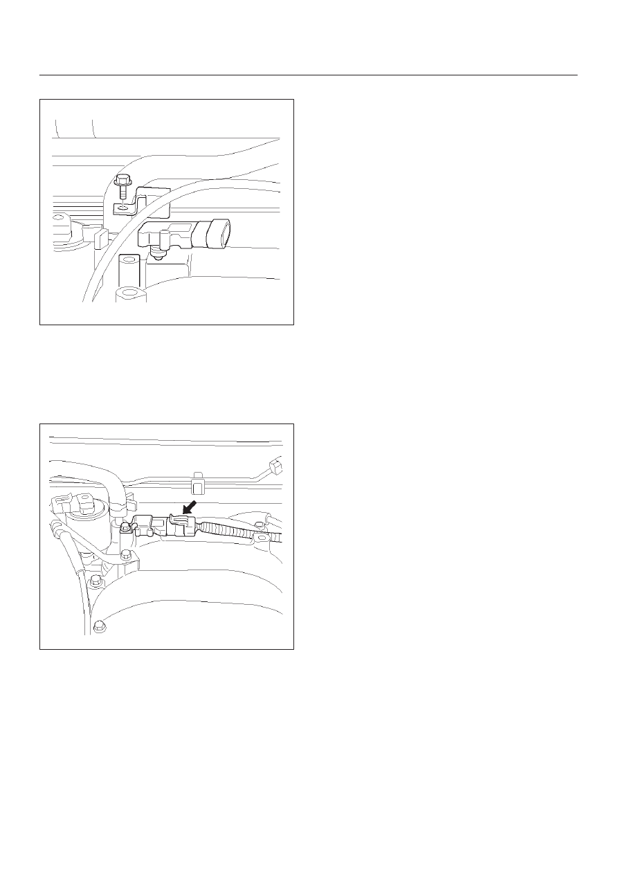
4. Remove the MAP sensor from the mounting bracket.
055RW002
Installation Procedure
1. Install the MAP sensor in the mounting bracket.
2. Install the mounting bracket retaining bolt on the
common chamber.
3. Connect the MAP electrical connector.
055RW005
4. Connect the negative battery cable.
Malfunction Indicator Lamp
(MIL)
Removal and Installation Procedure
Refer to Warning light bulb, indicator light valve,
illumination light bulb, A/T indicator light bulb in Meter and
Gauge.
Powertrain Control Module
(PCM)
Service Precaution
NOTE: To prevent possible electrostatic discharge
damage to the PCM, do not touch the connector pins or
soldered components on the circuit board.
Electrostatic Discharge (ESD)
Damage
Electronic components used in the control systems are
often designed to carry very low voltage. Electronic
components are susceptible to damage caused by
electrostatic discharge. Less than 100 volts of static
electricity can cause damage to some electronic
components. By comparison, it takes as much as 4,000
volts for a person to even feel the zap of a static
discharge.
There are several ways for a person to become statically
charged. The most common methods of charging are by
friction and by induction. An example of charging by
friction is a person sliding across a car seat.
Charging by induction occurs when a person with well
insulated shoes stands near a highly charged object and
momentarily touches ground. Charges of the same
polarity are drained off leaving the person highly charged
with the opposite polarity. Static charges can cause
damage, therefore, it is important to use care when
handling and testing electronic components.
NOTE: To prevent possible Electrostatic Discharge
damage, follow these guidelines:
D
Do not touch the control module connector pins or
soldered components on the control module circuit
board.
D
Do not open the replacement part package until the
part is ready to be installed.
D
Before removing the part from the package, ground
the package to a known good ground on the vehicle.
D
If the part has been handled while sliding across the
seat, or while sitting down from a standing position, or
while walking a distance, touch a known good ground
before installing the part.
NOTE: To prevent internal PCM damage, the ignition
must be in the “OFF” position in order to disconnect or
reconnect power to the PCM (for example: battery cable,
PCM pigtail, PCM fuse, jumper cables, etc.).
IMPORTANT:
When replacing the production PCM
with a service PCM, it is important to transfer the
broadcast code and production PCM number to the
service PCM label. This will allow positive identification of
PCM parts throughout the service life of the vehicle. Do
not record this information on the metal PCM cover.
IMPORTANT:
The ignition should always be in the
“OFF” position in order to install or remove the PCM
connectors.