Content .. 1207 1208 1209 1210 ..
Opel Frontera UE. Manual - part 1209
9J1–44
RESTRAINT CONTROL SYSTEM
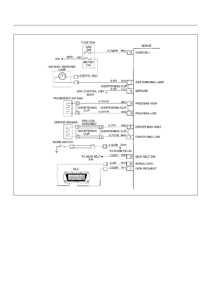
DTC 26 Driver Deployment Loop Open
D09RX002
Circuit Description:
When the ignition switch is turned “ON", the Sensing
and Diagnostic Module (SDM) will perform tests to
diagnose critical malfunctions within itself. Upon
passing these tests, “ignition 1", and deployment loop
voltages are measured to ensure they are within their
respective normal voltage ranges.
During “Continuous Monitoring" diagnostics, a fixed
amount of current is following in the deployment loop.
This produces proportional voltage drops in the loop.
By monitoring the voltage difference between “Driver
Bag High" and “Driver Bag Low", the SDM calculates
the combined resistance of the driver air bag assembly,
SRS coil assembly, harness wiring Circuits(CKTs)
IB05–YELLOW and IB06–YELLOW/BLACK, and
connector terminal contact.
DTC Will Set When:
The voltage difference between “Driver Bag High"
terminal “3" and “Driver Bag Low" terminal “4" is above
or equal to a specified value for 500 milliseconds during
“Continuous Monitoring."
Action Taken:
SDM turns “ON" the “AIR BAG" warning lamp and sets
a diagnostic trouble code.
DTC Will Clear When:
The voltage difference between “Driver Bag High"
terminal “3" and “Driver Bag Low" terminal “4" is below
a specified value for 500 milliseconds during
“Continuous Monitoring."