Nissan Leaf (2024 year). Manual in english - page 12
 

  Index      Manuals     Nissan Leaf (2024 year). Manual in english


Search            copyright infringement  


Content      ..     10      11      12      13     ..


Nissan Leaf (2024 year). Manual in english - page 12


• The radar sensors may not detect

slower moving vehicles if they are
passed quickly.

• If the driver activates the turn signal

before a vehicle enters the detection
zone, the side indicator light will flash
but no chime will sound when the
other vehicle is detected.

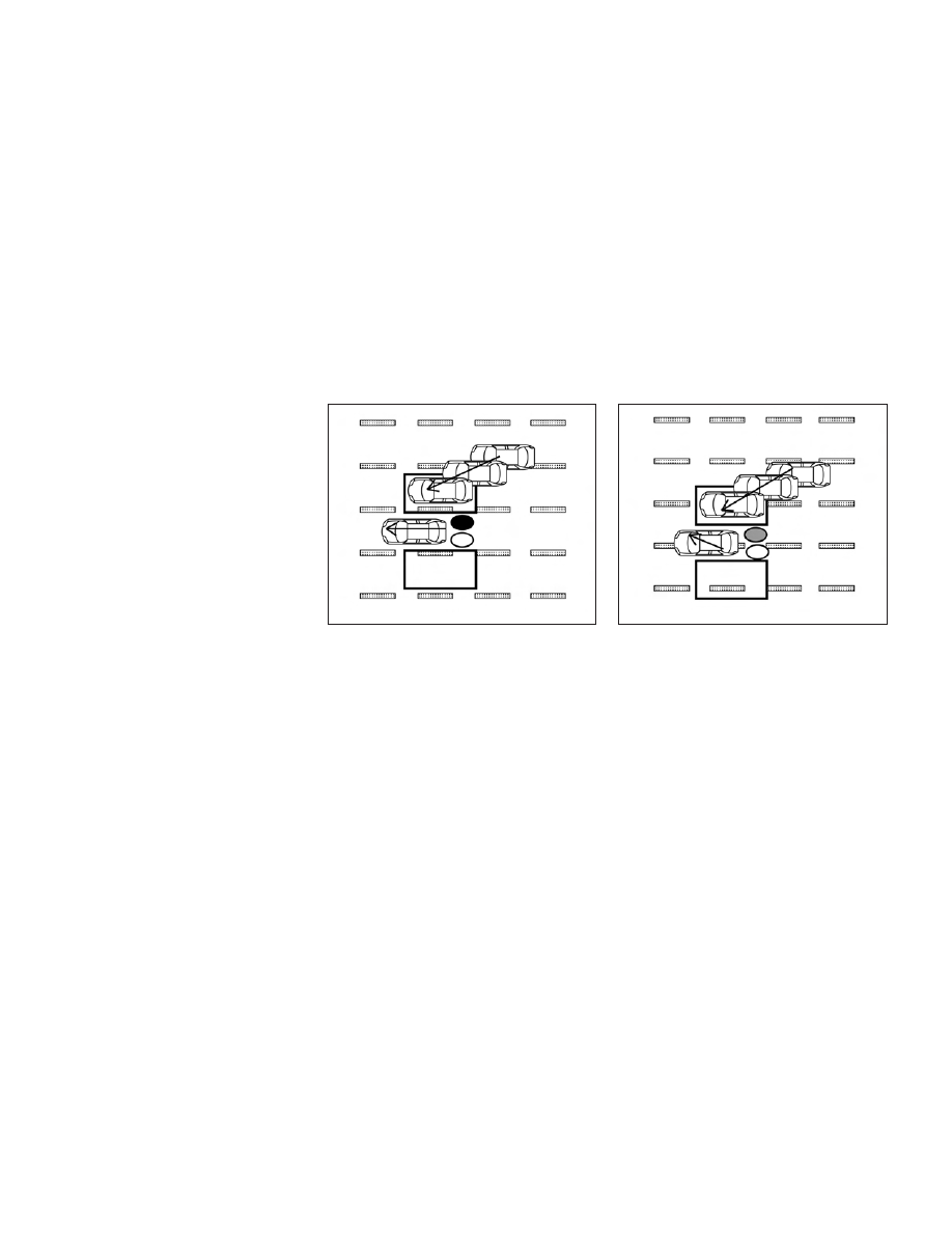
Entering from the side

Illustration 5:

The side indicator light illu-

minates if a vehicle enters the detection
zone from either side.

Illustration 6:

If the driver activates the

turn signal while another vehicle is in the
detection zone, then the system chimes
(twice) and the side indicator light flashes.

NOTE:
• If the driver activates the turn signal

before a vehicle enters the detection
zone, the side indicator light will flash
but no chime will sound when the
other vehicle is detected.

• The radar sensors may not detect a ve-

hicle which is traveling at about the
same speed as your vehicle when it en-
ters the detection zone.

LSD2884

Illustration 5 – Entering from the side

LSD2885

Illustration 6 – Entering from the side

5-42

Starting and driving

SYSTEM TEMPORARILY
UNAVAILABLE

When radar blockage is detected, the sys-
tem will be deactivated automatically. The
BSW indicator

O

1

will blink (yellow) in the

vehicle information display. The indicator
next to “Blind spot” in the “Driving Aids”
menu

O

2

will also blink (yellow).

The system is not available until the condi-
tions no longer exist.

The radar sensors may be blocked by tem-
porary ambient conditions such as splash-
ing water, mist or fog. The blocked condi-
tion may also be caused by objects such
as ice, frost or dirt obstructing the radar
sensors.

NOTE:

If the BSW system stops working, the
RCTA system will also stop working.

Action to take:

When the above conditions no longer exist,
the system will resume automatically.

LSD3769

Starting and driving

5-43

Malfunction

If the BSW system malfunctions, it will turn
off automatically. The BSW indicator will illu-
minate (yellow) in the vehicle information
display. The indicator next to “Blind spot” in
the “Driving Aids” menu will also illuminate
(yellow).

NOTE:

If the BSW system stops working, the
RCTA system will also stop working.

Action to take:

Stop the vehicle in a safe location, place the
vehicle in the P (Park) position, turn the EV
system off and restart the EV system. If the
indicators continue to appear, have the
system checked. It is recommended that
you visit a NISSAN certified LEAF dealer for
this service.

SYSTEM MAINTENANCE

The two radar sensors

O

1

for the BSW and

RCTA systems are located near the rear
bumper. Always keep the area near the
radar sensors clean.

The radar sensors may be blocked by tem-
porary ambient conditions such as splash-
ing water, mist or fog.

The blocked condition may also be caused
by objects such as ice, frost or dirt ob-
structing the radar sensors.

Check for and remove objects obstructing
the area around the radar sensors.

Do not attach stickers (including transpar-
ent material), install accessories or apply
additional paint near the radar sensors.

Do not strike or damage the area around
the radar sensors. It is recommended that
you visit a NISSAN certified LEAF dealer if
the area around the radar sensors is dam-
aged due to a collision.

Radio frequency statement
(Type A) (if so equipped)

For USA

This device complies with part 15 of the
FCC Rules. Operation is subject to the fol-
lowing two conditions:

(1) This device may not cause harmful
interference, and (2) this device must ac-
cept any interference received, including
interference that may cause undesired
operation.

FCC Warning

Changes or modifications not expressly
approved by the party responsible for
compliance could void the user’s author-
ity to operate the equipment.

LSD3768

5-44

Starting and driving

For Canada

Applicable law: Canada 310

This

device

complies

with

Industry

Canada licence-exempt RSS standard(s).
Operation is subject to the following two
conditions: (1) This device may not cause
interference, and (2) This device must ac-
cept any interference, including interfer-
ence that may cause undesired opera-
tion of the device.

Frequency bands: 24.05–24.25GHz

Output power: less than 20 milliwatts

Radio frequency statement
(Type B) (if so equipped)

For USA

This device complies with part 15 of the
FCC Rules. Operation is subject to the fol-
lowing two conditions:

(1) This device may not cause harmful
interference, and (2) this device must ac-
cept any interference received, including
interference that may cause undesired
operation.

FCC Warning

Changes or modifications not expressly
approved by the party responsible for
compliance could void the user’s author-
ity to operate the equipment.

For Canada

Applicable law: Canada 310

This

device

contains

licence-exempt

transmitter(s)/receiver(s) that comply
with Innovation, Science and Economic
Development Canada’s licence-exempt
RSS(s). Operation is subject to the fol-
lowing two conditions:

1. This device may not cause interference.

2. This device must accept any interfer-
ence, including interference that may
cause undesired operation of the device.

Radiofrequency radiation exposure in-
formation: This equipment complies
with radiation exposure limits set forth
for an uncontrolled environment. This
equipment should be installed and oper-
ated with minimum distance of 20 cm
between the radiator and your body.

WARNING

Failure to follow the warnings and in-
structions for proper use of the I-BSI
system could result in serious injury or
death.

The I-BSI system is not a replace-
ment for proper driving procedure
and is not designed to prevent con-
tact with vehicles or objects. When
changing lanes, always use the side
and rear mirrors and turn and look in
the direction you will move to ensure
it is safe to change lanes. Never rely
solely on the I-BSI system.

There is a limitation to the detection
capability of the radar or the sonar.
Not every moving object or vehicle
will be detected. Using the I-BSI sys-
tem under some road, ground, lane
marker, traffic or weather conditions
could lead to improper system op-
eration. Always rely on your own op-
eration to avoid accidents.

The I-BSI system helps alert the driver of
other vehicles in adjacent lanes when
changing lanes, and helps assist the driver
to return the vehicle to the center of the
traveling lane.

INTELLIGENT BLIND SPOT
INTERVENTION (I-BSI)

Starting and driving

5-45

The I-BSI system uses radar sensors

O

1

installed near the rear bumper to detect
other vehicles in an adjacent lane. In addi-
tion to the radar sensors, the I-BSI system
uses a camera

O

2

installed behind the

windshield to monitor the lane markers of
your traveling lane.

The radar sensors can detect vehicles on
either side of your vehicle within the detec-
tion zone shown as illustrated.

The detection zone starts from the outside
mirror of your vehicle and extends approxi-
mately 10ft (3.0m) behind the rear bumper,
and approximately 10ft (3.0 m) sideways.

LSD3770

SSD1030

Detection zone

5-46

Starting and driving

1. Side indicator light

2. Blind Spot Warning (BSW) indicator

3. Intelligent Blind Spot Intervention (I-BSI)

indicator

4. Dynamic driver assistance switch

(models without ProPILOT Assist)

5. ProPILOT Assist switch (models with

ProPILOT Assist)

I-BSI SYSTEM OPERATION

The I-BSI system operates above approxi-
mately 37 mph (60 km/h).

If the radar sensors detect a vehicle in the
detection zone, the side indicator light (1)
illuminates.

If the turn signal is then activated, the sys-
tem chimes (twice) and the side indicator
light flashes. The side indicator light con-
tinues to flash until the detected vehicle
leaves the detection zone. The brightness
of the side indicator light is adjusted auto-
matically depending on the brightness of
the ambient light.

If the I-BSI system is ON and your vehicle
approaches a lane marker while another
vehicle is in the detection zone, the system
chimes (three times) and the side indicator
light flashes. The I-BSI system activates to
help return the vehicle back to the center of
the driving lane. The I-BSI system operates
regardless of turn signal usage.

LSD4768

Starting and driving

5-47

NOTE:
• I-BSI warning and system application

will only be activated if the side indicator
light is already illuminated when your
vehicle approaches a lane marker. If an-
other vehicle comes into the detection
zone after your vehicle has crossed a
lane marker, no I-BSI warning or system
application will be activated. For addi-
tional information, see “I-BSI driving
situations” (P. 5-50).

• The I-BSI system is typically activated

earlier than the Intelligent Lane Inter-
vention (I-LI) system when your vehicle
is approaching a lane marker.

To turn on the I-BSI system, push the Pro-
PILOT Assist switch on the steering wheel
(models with ProPILOT Assist) or the dy-
namic driver assistance switch (models
without ProPILOT Assist) after starting the
EV system. The I-BSI indicator will illumi-
nate. Push the ProPILOT Assist switch or
the dynamic driver assistance switch
again to turn off the I-BSI system. The I-BSI
indicator will turn off.

HOW TO ENABLE/DISABLE THE
I-BSI SYSTEM

LSD3651

5-48

Starting and driving

Perform the following steps to enable or
disable the I-BSI system:

1. Press the

button until “Settings” dis-

plays in the vehicle information display.
Use the

button to select “Driver

Assistance.” Then press the OK button.

2. Select “Blind Spot” and press the OK

button.

3. Select “Blind Spot Intervention” and use

the OK button to turn the system on or
off.

4. Push the ProPILOT Assist switch (mod-

els with ProPILOT Assist) or the dynamic
driver assistance switch (models with-
out ProPILOT Assist) to turn the system
on or off.

NOTE:

When Blind Spot Intervention is ON in
the settings menu, turning the ProPILOT
Assist switch (if so equipped) ON will
activate the Intelligent Blind Spot Inter-
vention (I-BSI) system at the same time.
For additional information, see “Intelli-
gent Lane Intervention (I-LI)” (P. 5-30).

I-BSI SYSTEM LIMITATIONS

WARNING

Listed below are the system limitations
for the I-BSI system. Failure to operate
the vehicle in accordance with these
system limitations could result in seri-
ous injury or death.

The I-BSI system cannot detect all
vehicles under all conditions.

The radar sensors may not be able to
detect and activate I-BSI when cer-
tain objects are present such as:

Pedestrians, bicycles, or animals.

Vehicles such as motorcycles, low

height vehicles, or high ground
clearance vehicles.

Vehicles remaining in the detection

zone when you accelerate from a
stop. For additional information,
see “BSI driving situations” (P. 5-50).

Oncoming vehicles.

A vehicle merging into an adjacent

lane at a speed approximately the
same as your vehicle.

A vehicle approaching rapidly from

behind.

A vehicle which your vehicle over-

takes rapidly.

A vehicle that passes through the

detection zone quickly.

The radar sensors’ detection zone is
designed based on a standard lane
width. When driving in a wider lane,
the radar sensors may not detect
vehicles in an adjacent lane. When
driving in a narrow lane, the radar
sensors may detect vehicles driving
two lanes away.

The radar sensors are designed to
ignore most stationary objects; how-
ever, objects such as guardrails, walls,
foliage and parked vehicles may occa-
sionally be detected. This is a normal
operation condition.

The camera may not detect lane
markers in the following situations
and the I-BSI system may not oper-
ate properly.

On roads where there are multiple

parallel lane markers; lane mark-
ers that are faded or not painted
clearly; yellow painted lane mark-
ers; non-standard lane markers;
lane markers covered with water,
dirt, snow, etc.

On roads where discontinued lane

markers are still detectable.

Starting and driving

5-49

On roads where there are sharp

curves.

On roads where there are sharply

contrasting objects, such as shad-
ows, snow, water, wheel ruts,
seams or lines remaining after
road repairs.

On roads where the traveling lane

merges or separates.

When the vehicle’s traveling direc-

tion does not align with the lane
markers.

When traveling close to the vehicle

in front of you, which obstructs the
lane camera unit detection range.

When rain, snow or dirt adheres to

the windshield in front of a lane
camera unit.

When

the

headlights

are

not

bright due to dirt on the lens or if
aiming is not adjusted properly.

When strong light enters a lane

camera unit. (For example: light
directly shines on the front of the
vehicle at sunrise or sunset.)

When a sudden change in bright-

ness occurs. (For example: when
the vehicle enters or exits a tunnel
or under a bridge.)

Do not use the I-BSI system under the
following conditions because the
system may not function properly.

During bad weather (for example:

rain, fog, snow, etc.).

When driving on slippery roads,

such as on ice or snow, etc.

When driving on winding or un-

even roads.

When there is a lane closure due to

road repairs.

When driving in a makeshift or

temporary lane.

When driving on roads where the

lane width is too narrow.

When driving with a tire that is not

within normal tire conditions (e.g.,
tire wear, low tire pressure, instal-
lation of spare tire, tire chains,
nonstandard wheels).

When the vehicle is equipped with

non-original brake parts or sus-
pension parts.

Excessive noise (e.g., audio system
volume, open vehicle window) will in-
terfere with the chime sound, and it
may not be heard.

I-BSI DRIVING SITUATIONS

Indicator on

Indicator off

Indicator flashing

5-50

Starting and driving

Another vehicle approaching
from behind

Illustration 1: The side indicator light illumi-
nates if a vehicle enters the detection zone
from behind in an adjacent lane.

Illustration 2: If the driver activates the turn
signal then the system chimes a sound
(twice) and the side indicator light flashes.

Illustration 3: If the I-BSI system is on and
your vehicle approaches a lane marker
while another vehicle is in the detection
zone, the system chimes (three times) and
the side indicator light flashes. Then the
I-BSI system activates to help return the
vehicle back to the center of the driving
lane.

NOTE:
• The radar sensors may not detect ve-

hicles which are approaching rapidly
from behind.

LSD2299

Illustration 1 – Approaching from behind

LSD2300

Illustration 2 – Approaching from behind

LSD3775

Illustration 3 – Approaching from behind

Starting and driving

5-51

• If the driver activates the turn signal

before a vehicle enters the detection
zone, the side indicator light will flash
but no chime will sound when the
other vehicle is detected.

Overtaking another vehicle

Illustration 4: The side indicator light illumi-
nates if you overtake a vehicle and that
vehicle stays in the detection zone for ap-
proximately 3 seconds.

Illustration 5: If the driver activates the turn
signal while another vehicle is in the detec-
tion zone, then the system chimes (twice)
and the side indicator light flashes.

LSD2302

Illustration 4– Overtaking another

vehicle

LSD2303

Illustration 5– Overtaking another

vehicle

5-52

Starting and driving

Illustration 6: If the I-BSI system is on and
your vehicle approaches a lane marker
while another vehicle is in the detection
zone, the system chimes (three times) and
the side indicator light flashes. The I-BSI
system activates to help return the vehicle
back to the center of the driving lane.

NOTE:
• When overtaking several vehicles in a

row, the vehicles after the first vehicle
may not be detected if they are travel-
ing close together.

• The radar sensors may not detect

slower moving vehicles if they are
passed quickly.

• If the driver activates the turn signal

before a vehicle enters the detection
zone, the side indicator light will flash
but no chime will sound when the
other vehicle is detected.

Entering from the side

Illustration 7: The side indicator light illumi-
nates if a vehicle enters the detection zone
from either side.

NOTE:

The radar sensors may not detect a ve-
hicle which is traveling at about the same
speed as your vehicle when it enters the
detection zone.

LSD2072

Illustration 6– Overtaking another

vehicle

LSD2305

Illustration 7– Entering from the side

Starting and driving

5-53

Illustration 8: If the driver activates the turn
signal while another vehicle is in the detec-
tion zone, then the side indicator light
flashes and a chime will sound twice.

NOTE:

If the driver activates the turn signal be-
fore a vehicle enters the detection zone,
the side indicator light will flash but no
chime will sound when another vehicle is
detected.

Illustration 9: If the I-BSI system is on and
your vehicle approaches the lane marker
while another vehicle is in the detection
zone, the system chimes (three times) and
the side indicator light flashes. The I-BSI
system activates to help return the vehicle
back to the center of the driving lane.

Illustration 10: The I-BSI system will not op-
erate if your vehicle is on a lane marker
when another vehicle enters the detection
zone. In this case only the BSW system
operates.

NOTE:
• The radar sensors may not detect a

vehicle which is traveling at about the
same speed as your vehicle when it
enters the detection zone.

LSD2308

Illustration 8– Entering from the side

SSD1094

Illustration 9– Entering from the side

LSD2051

Illustration 10: – Entering from the side

5-54

Starting and driving

• If the driver activates the turn signal

before a vehicle enters the detection
zone, the side indicator light will flash
but no chime will sound when the
other vehicle is detected.

• I-BSI will not operate or will stop oper-

ating and only a warning chime will
sound under the following conditions:

– When the brake pedal is depressed.
– When the vehicle is accelerated dur-

ing I-BSI system operation.

– When steering quickly.
– When the ICC, I-FCW or AEB with Pe-

destrian Detection warnings sound.

– When the hazard warning flashers

are operated.

– When driving on a curve at a high

speed.

SYSTEM TEMPORARILY
UNAVAILABLE

Under the following conditions, a chime will
sound, the following message will appear
in the vehicle information display and the
I-BSI system will be turned off automati-
cally. The I-BSI system will not be available
until the conditions no longer exist.
• “Not available Poor Road Conditions”

• When the VDC system (except TCS func-

tion) or ABS operates.

• “Currently not available”
• When the VDC system is turned off.

Action to take:

When the above conditions no longer exist,
push the ProPILOT Assist switch (models
with ProPILOT Assist) or the dynamic driver
assistance switch (models without ProPI-
LOT Assist) again to turn the I-BSI system
back on.

When radar blockage is detected, the I-BSI
system will be turned off automatically, a
chime will sound and the “Unavailable: Side
Radar Obstruction” warning message will
appear in the vehicle information display.

The I-BSI system is not available until the
conditions no longer exist. For additional
information, see “System maintenance”
(P. 5-56).

Action to take:

When the above conditions no longer exist,
turn the I-BSI system on again. If the “Un-
available: Side Radar Obstruction” warning
message appears even after the I-BSI sys-
tem is turned on again, stop the vehicle in a

safe location, place the vehicle in the P
(Park) position and turn the EV system off.
Check for and remove objects obscuring
the radar sensors on the rear bumper, and
restart the EV system.

If the vehicle is parked in direct sunlight
under high temperature conditions (over
approximately 104°F (40°C)) and then the
I-BSI system is turned on, the I-BSI sys-
tem may be deactivated automatically.
The “Unavailable: High Cabin Temperature”
warning message will appear in the vehicle
information display.

Action to take:

When the interior temperature is reduced,
push the ProPILOT Assist switch (models
with ProPILOT Assist) or the dynamic driver
assistance switch (models without ProPI-
LOT Assist) again to turn the I-BSI system
back on.

Starting and driving

5-55

SYSTEM MALFUNCTION

When the I-BSI system malfunctions, it will
be turned off automatically, a chime will
sound, and the “Not available System Mal-
function” warning message with the BSW
indicator (orange) will appear in the vehicle
information display.

Action to take:

Stop the vehicle in a safe location, place the
vehicle in the P (Park) position, turn the EV
system off and restart the EV system. If the
“Not available System Malfunction” warning
message with the BSW indicator (orange)
continues to be displayed, have the I-BSI
system checked. It is recommended you
visit a NISSAN certified LEAF dealer for this
service.

SYSTEM MAINTENANCE

The two radar sensors

O

1

for the I-BSI

system are located near the rear bumper.
Always keep the area near the radar sen-
sors clean.

The radar sensors may be blocked by tem-
porary ambient conditions such as splash-
ing water, mist or fog.

The blocked condition may also be caused
by objects such as ice, frost or dirt ob-
structing the radar sensors.

Check for and remove objects obstructing
the radar sensors.

Do not attach stickers (including transpar-
ent material), install accessories or apply
additional paint near the radar sensors.

Do not strike or damage the area around
the radar sensors.

It is recommended you visit a NISSAN certi-
fied LEAF dealer if the area around the radar
sensors is damaged due to a collision.

The lane camera unit

O

2

for I-BSI system is

located above the inside mirror. To keep
the proper operation of I-BSI and prevent a
system malfunction, be sure to observe
the following:
• Always keep the windshield clean.
• Do not attach a sticker (including trans-

parent material) or install an accessory
near the camera unit.

• Do not place reflective materials, such as

white paper or a mirror, on the instru-
ment panel. The reflection of sunlight
may adversely affect the camera unit’s
capability of detecting the lane markers.

• Do not strike or damage the areas

around the camera unit. Do not touch the
camera lens or remove the screw located
on the camera unit. It is recommended
that you contact a NISSAN certified LEAF
dealer if the camera unit is damaged due
to an accident.

LSD3770

5-56

Starting and driving

Radio frequency statement
(Type A) (if so equipped)

For USA

This device complies with part 15 of the
FCC Rules. Operation is subject to the
following two conditions:

(1) This device may not cause harmful
interference, and (2) this device must ac-
cept any interference received, including
interference that may cause undesired
operation.

FCC Warning

Changes or modifications not expressly
approved by the party responsible for
compliance could void the user’s author-
ity to operate the equipment.

For Canada

Applicable law: Canada 310

This

device

complies

with

Industry

Canada licence-exempt RSS standard(s).
Operation is subject to the following two
conditions: (1) This device may not cause
interference, and (2) This device must
accept any interference, including inter-
ference that may cause undesired op-
eration of the device.

Frequency bands: 24.05–24.25GHz

Output power: less than 20 milliwatts

Radio frequency statement
(Type B) (if so equipped)

For USA

This device complies with part 15 of the
FCC Rules. Operation is subject to the fol-
lowing two conditions:

(1) This device may not cause harmful
interference, and (2) this device must ac-
cept any interference received, including
interference that may cause undesired
operation.

FCC Warning

Changes or modifications not expressly
approved by the party responsible for
compliance could void the user’s author-
ity to operate the equipment.

For Canada

Applicable law: Canada 310

This

device

contains

licence-exempt

transmitter(s)/receiver(s) that comply
with Innovation, Science and Economic
Development Canada’s licence-exempt
RSS(s). Operation is subject to the fol-
lowing two conditions:

1. This device may not cause interference.

2. This device must accept any interfer-
ence, including interference that may
cause undesired operation of the device.

Radiofrequency radiation exposure in-
formation: This equipment complies
with radiation exposure limits set forth
for an uncontrolled environment. This
equipment should be installed and oper-
ated with minimum distance of 20 cm
between the radiator and your body.

Starting and driving

5-57

WARNING

Failure to follow the warnings and in-
structions for proper use of the RCTA
system could result in serious injury or
death.

The RCTA system is not a replace-
ment for proper driving procedures
and is not designed to prevent con-
tact with vehicles or objects. When
backing out of a parking space, al-
ways use the side and rear mirrors
and turn and look in the direction
your vehicle will move. Never rely
solely on the RCTA system.

The RCTA system will assist you when
backing out from a parking space. When
the vehicle is in reverse, the system is de-
signed to detect other vehicles approach-
ing from the right or left of the vehicle. If the
system detects cross traffic, it will alert you.

RCTA SYSTEM OPERATION

1. Side Indicator Light

LSD4769

REAR CROSS TRAFFIC ALERT (RCTA)

5-58

Starting and driving

The RCTA system can help alert the driver
of an approaching vehicle when the driver
is backing out of a parking space.

When the shift position is in R (Reverse) and
the vehicle speed is less than approxi-
mately 5 mph (8 km/h), the RCTA system is
operational.

If the radar detects an approaching vehicle
from either side, the system chimes (once)
and the side indicator light (1) flashes on the
side the vehicle is approaching from.

The RCTA system uses radar sensors

O

1

installed on both sides near the rear bum-
per to detect an approaching vehicle.

The radar sensors

O

1

can detect an ap-

proaching vehicle from up to approxi-
mately 66 ft (20 m) away.

LSD2886

LSD3768

Starting and driving

5-59

HOW TO ENABLE/DISABLE THE
RCTA SYSTEM

Perform the following steps to enable or
disable the RCTA system.

1. Press the

button until “Settings” dis-

plays in the vehicle information display.
Use the

button to select “Driver

Assistance.” Then press the OK button.

2. Select “Parking Aids” and press the OK

button.

3. Select “Cross Traffic” and use the OK but-

ton to turn the system on or off.

NOTE:

When enabling/disabling the system, the
system setting will be retained even if the
EV system is restarted.

LSD3771

5-60

Starting and driving

RCTA SYSTEM LIMITATIONS

WARNING

Listed below are the system limitations
for the RCTA system. Failure to operate
the vehicle in accordance with these
system limitations could result in seri-
ous injury or death.

Always check surroundings and turn
to check what is behind you before
backing up. The radar sensors detect
approaching (moving) vehicles. The
radar sensors cannot detect every
object such as:

Pedestrians, bicycles, motorcycles,

animals

or

child-operated

toy

vehicles

A vehicle that is passing at speeds

greater than approximately 19 mph
(30 km/h)

A vehicle that is passing at speeds

lower than approximately 5 mph
(8 km/h)

The radar sensors may not detect
approaching vehicles in certain situ-
ations:

Illustration

a: When

a

vehicle

parked next to you obstructs the
beam of the radar sensor.

Illustration b: When the vehicle is

parked in an angled parking space.

Illustration c: When the vehicle is

parked on inclined ground.

Illustration d: When an approach-

ing vehicle turns into your vehi-
cle’s parking lot aisle.

LSD2887

Starting and driving

5-61

Illustration e: When the angle

formed by your vehicle and ap-
proaching vehicle is small.

The following conditions may reduce
the ability of the radar to detect other
vehicles:

Severe weather

Road spray

Ice/frost/snow/dirt build-up on the

vehicle

Do not attach stickers (including
transparent material), install acces-
sories or apply additional paint near
the radar sensors. These conditions
may reduce the ability of the radar to
detect other vehicles.

Excessive noise (e.g., audio system
volume, open vehicle window) will in-
terfere with the chime sound, and it
may not be heard.

NOTE:

In the case of several vehicles approach-
ing in a row (Illustration 1) or in the oppo-
site direction (Illustration 2), a chime may
not be sounded by the RCTA system af-
ter the first vehicle passes the sensors.

LSD2888

Illustration 1

LSD2889

Illustration 2

5-62

Starting and driving

SYSTEM TEMPORARILY
UNAVAILABLE

When radar blockage is detected, the sys-
tem will be deactivated automatically.

The systems are not available until the con-
ditions no longer exist.

The radar sensors may be blocked by tem-
porary ambient conditions such as splash-
ing water, mist or fog.

The blocked condition may also be caused
by conditions such as ice, snow, frost or dirt
obstructing the radar sensors.

NOTE:

If the BSW system stops working, the
RCTA system will also stop working.

Action to take

When the above conditions no longer exist,
the system will resume automatically.

Malfunction

When the RCTA system malfunctions, it
will turn off automatically. The “Malfunction:
See Owner’s Manual” warning message will
appear.

NOTE:

If the BSW system stops working, the
RCTA system will also stop working.

Action to take

Stop the vehicle in a safe location, place the
vehicle in the P (Park) position, turn the
EV system off and restart the EV system.
If the system does not resume automati-
cally, have the system checked. It is recom-
mended that you visit a NISSAN certified
LEAF dealer for this service.

SYSTEM MAINTENANCE

The two radar sensors

O

1

for the BSW and

RCTA systems are located near the rear
bumper. Always keep the area near the
radar sensors clean.

The radar sensors may be blocked by tem-
porary ambient conditions such as splash-
ing water, mist or fog.

The blocked condition may also be caused
by objects such as ice, frost or dirt ob-
structing the radar sensors.

Check for and remove objects obstructing
the area around the radar sensors.

LSD3768

Starting and driving

5-63

Do not attach stickers (including transpar-
ent material), install accessories or apply
additional paint near the radar sensors.

Do not strike or damage the area around
the radar sensors. It is recommended that
you visit a NISSAN certified LEAF dealer if
the area around the radar sensors is dam-
aged due to a collision.

Radio frequency statement
(Type A) (if so equipped)

For USA

This device complies with part 15 of the
FCC Rules. Operation is subject to the fol-
lowing two conditions:

(1) This device may not cause harmful
interference, and (2) this device must ac-
cept any interference received, including
interference that may cause undesired
operation.

FCC Warning

Changes or modifications not expressly
approved by the party responsible for
compliance could void the user’s author-
ity to operate the equipment.

For Canada

Applicable law: Canada 310

This

device

complies

with

Industry

Canada licence-exempt RSS standard(s).
Operation is subject to the following two
conditions: (1) This device may not cause
interference, and (2) This device must
accept any interference, including inter-
ference that may cause undesired op-
eration of the device.

Frequency bands: 24.05–24.25GHz

Output power: less than 20 milliwatts

Radio frequency statement
(Type B) (if so equipped)

For USA

This device complies with part 15 of the
FCC Rules. Operation is subject to the fol-
lowing two conditions:

(1) This device may not cause harmful
interference, and (2) this device must ac-
cept any interference received, including
interference that may cause undesired
operation.

FCC Warning

Changes or modifications not expressly
approved by the party responsible for
compliance could void the user’s author-
ity to operate the equipment.

For Canada

Applicable law: Canada 310

This

device

contains

licence-exempt

transmitter(s)/receiver(s) that comply
with Innovation, Science and Economic
Development Canada’s licence-exempt
RSS(s). Operation is subject to the fol-
lowing two conditions:

1. This device may not cause interference.

2. This device must accept any interfer-
ence, including interference that may
cause undesired operation of the device.

Radiofrequency radiation exposure in-
formation: This equipment complies
with radiation exposure limits set forth
for an uncontrolled environment. This
equipment should be installed and oper-
ated with minimum distance of 20 cm
between the radiator and your body.

5-64

Starting and driving

1. RES+ switch

2. CANCEL switch

3. SET- switch

4. Cruise control switch

PRECAUTIONS ON CRUISE
CONTROL

• If the cruise control system malfunctions,

it cancels automatically. The cruise
indicator in the vehicle information dis-
play then blinks to warn the driver.

• If the cruise

indicator blinks, turn the

cruise control switch off and have the
system checked. It is recommended that
you visit a NISSAN certified LEAF dealer for
this service.

• The cruise

indicator may blink when

the cruise control switch is turned on
while pushing the RES+, SET- or CANCEL
switch. To properly set the cruise control
system, use the following procedures.

WARNING

Do not use the cruise control when driv-
ing under the following conditions:

When it is not possible to keep the
vehicle at a set speed

In heavy traffic or in traffic that varies
in speed

On winding or hilly roads

On slippery roads (rain, snow, ice,
etc.)

In very windy areas

Doing so could cause a loss of vehicle
control and result in an accident.

CRUISE CONTROL OPERATIONS

The cruise control allows driving at a speed
between 25 to 90 mph (40 to 144 km/h)
without keeping your foot on the accelera-
tor pedal.

To turn on the cruise control,

push the

cruise control switch on. The cruise
indicator in the vehicle information display
will illuminate.

To set the cruising speed,

accelerate the

vehicle to the preferred speed, push the
SET- switch and release it. Take your foot
off the accelerator pedal. The vehicle will
maintain the set speed.

To pass another vehicle,

depress the ac-

celerator pedal. When you release the
pedal, the vehicle will return to the previ-
ously set speed.

• The vehicle may not maintain the set

speed on winding or hilly roads. If this
happens, drive without using the cruise
control.

To cancel the preset speed,

use one of the

following methods:

1. Push the CANCEL switch.

2. Tap the brake pedal.

LSD3168

CRUISE CONTROL (if so equipped)

Starting and driving

5-65

3. Turn the cruise control switch off. The

cruise

indicator in the vehicle infor-

mation display will turn off.

• If you depress the brake pedal while

pushing the RES+ or SET- switch and re-
set at the cruising speed, the cruise con-
trol will disengage. Turn the cruise control
switch off once and then turn it on again.

• The cruise control will automatically can-

cel if the vehicle slows more than 8 mph
(13 km/h) below the set speed.

• If you move the shift lever to the N (Neu-

tral) position, the cruise control will be
canceled.

To reset at a faster cruising speed,

use

one of the following methods:
• Depress the accelerator pedal. When the

vehicle attains the preferred speed, push
and release the SET- switch.

• Push and hold the RES+ switch. When the

vehicle attains the preferred speed, re-
lease the switch.

• Push, then quickly release the RES+ switch.

Each time you do this, the set speed will
increase by about 1 mph or 1.6 km/h.

To reset at a slower cruising speed,

use

one of the following methods:
• Lightly tap the brake pedal. When the ve-

hicle attains the preferred speed, push
the SET- switch and release it.

• Push and hold the SET- switch. Release

the switch when the vehicle slows down
to the preferred speed.

• Push, then quickly release, the SET- switch.

Each time you do this, the set speed will
decrease by about 1 mph or 1km/h.

To resume the preset speed,

push and

release the RES+ switch. The vehicle will
resume the last set cruising speed when
the vehicle speed is over 25 mph (40 km/h).

5-66

Starting and driving

WARNING

Failure to follow the warnings and in-
structions for proper use of the ICC sys-
tem could result in serious injury or
death.

The ICC system is only an aid to assist
the driver and is not a collision
warning or avoidance device. It is the
driver’s responsibility to stay alert,
drive safely, and be in control of the
vehicle at all times.

Always observe posted speed limits
and do not set the speed over them.

Always drive carefully and atten-
tively when using the ICC system.
Read and understand the Owner’s
Manual thoroughly before using the
ICC system. To avoid serious injury or
death, do not rely on the system to
prevent accidents or to control the
vehicle’s speed in emergency situa-
tions. Do not use the ICC system ex-
cept in appropriate road and traffic
conditions.

LSD3654

INTELLIGENT CRUISE CONTROL (ICC)
(for vehicles without ProPILOT
Assist) (if so equipped)

Starting and driving

5-67

In the conventional (fixed speed)
cruise control mode, a warning chime
will not sound to warn you if you are
too close to the vehicle ahead. Pay
special attention to the distance be-
tween your vehicle and the vehicle
ahead of you or a collision could occur

NOTE:

For vehicles equipped with ProPILOT As-
sist, see “ProPILOT Assist” (P. 5-91)

The ICC system maintains a selected dis-
tance from the vehicle in front of you within
the speed range of 0 to 90 mph (0 to 144
km/h) up to the set speed. The set speed
can be selected by the driver between 20 to
90 mph (32 to 144 km/h).

The vehicle travels at a set speed when the
road ahead is clear.

The ICC system can be set to one of two
cruise control modes:

Vehicle-to-vehicle

distance

control

mode:

For maintaining a selected dis-

tance between your vehicle and the
vehicle in front of you up to the present
speed

Conventional (fixed speed) cruise con-
trol mode:

For cruising at a preset speed

Push the ICC switch

O

A

to choose the

cruise control mode between the vehicle-
to-vehicle distance control mode and the
conventional (fixed speed) cruise control
mode.

Once a control mode is activated, it cannot
be changed to the other cruise control
mode. To change the mode, push the ICC
switch

O

A

once to turn the system off. Then

push the ICC switch

O

A

again to turn the

system back on and select the desired
cruise control mode.

Always confirm the setting in the ICC sys-
tem display.

For the vehicle-to-vehicle distance control
mode, see “Vehicle-to-vehicle distance
control mode” (P. 5-69).

For the conventional (fixed speed) cruise
control mode, see “Conventional (fixed
speed) cruise control mode” (P. 5-86).

5-68

Starting and driving

HOW TO SELECT THE CRUISE
CONTROL MODE

Selecting the vehicle-to-vehicle distance
control mode:

To choose the vehicle-to-

vehicle distance control mode

O

1

, quickly

push and release the ICC switch

O

A

.

Selecting the conventional (fixed speed)
cruise control mode:

To choose the con-

ventional (fixed speed) cruise control mode

O

2

, push and hold the ICC switch

O

A

for

longer than approximately 1.5 seconds. For
additional information, see “Conventional
(fixed speed) cruise control mode” (P. 5-86).

VEHICLE-TO-VEHICLE DISTANCE
CONTROL MODE

In the vehicle-to-vehicle distance control
mode, the ICC system automatically main-
tains a selected distance from the vehicle
traveling in front of you according to that
vehicle’s speed (up to the set speed), or at
the set speed when the road ahead is clear.

The ICC system is intended to enhance
the operation of the vehicle when following
a vehicle traveling in the same lane and
direction.

LSD2891

LSD2850

Starting and driving

5-69

If the radar sensor

O

B

detects a slower

moving vehicle ahead, the system will re-
duce the vehicle speed so that your vehicle
follows the vehicle in front at the selected
distance.

The system automatically controls the
throttle and applies the brakes (up to ap-
proximately 40% of vehicle braking power)
if necessary.

The detection range of the sensor is ap-
proximately 650 ft (200 m) ahead.

VEHICLE-TO-VEHICLE DISTANCE
CONTROL MODE OPERATION

The vehicle-to-vehicle distance control
mode is designed to maintain a selected
distance from the vehicle in front of you

LSD3772

5-70

Starting and driving

and can reduce the speed to match a
slower vehicle ahead. The system will de-
celerate the vehicle as necessary and if the
vehicle ahead comes to a stop, the vehicle
decelerates to a standstill. However, the ICC
system can only apply up to 40% of the
vehicle’s total braking power.

This system should only be used when
traffic conditions allow vehicle speeds to
remain fairly constant or when vehicle
speeds change gradually. If a vehicle
moves into the traveling lane ahead or if a
vehicle traveling ahead rapidly decelerates,
the distance between vehicles may be-
come closer because the ICC system can-
not decelerate the vehicle quickly enough.
If this occurs, the ICC system will sound a
warning chime and blink the system dis-
play to notify the driver to take necessary
action.

The system will cancel and a warning
chime will sound if the speed is below ap-
proximately 15 mph (24 km/h) and a vehicle
is not detected ahead. The system will also
disengage when the vehicle goes above
the maximum set speed.

For additional information, see “Approach
warning” (P. 5-77).

The following items are controlled in the
vehicle-to-vehicle distance control mode:
• When there are no vehicles traveling

ahead, the vehicle-to-vehicle distance
control mode maintains the speed set
by the driver. The set speed range is be-
tween approximately 20 and 90 mph
(32 and 144 km/h).

• When there is a vehicle traveling ahead,

the vehicle-to-vehicle distance control
mode adjusts the speed to maintain the
distance, selected by the driver, from the
vehicle ahead. If the vehicle ahead comes
to a stop, the vehicle decelerates to a
standstill within the limitations of the sys-
tem. The system will cancel once it judges
a standstill with a warning chime.

• When the vehicle traveling ahead has

moved out from its lane of travel, the
vehicle-to-vehicle distance control mode
accelerates and maintains vehicle speed
up to the set speed.

The ICC system does not control vehicle
speed or warn you when you approach
stationary and slow-moving vehicles. You
must pay attention to vehicle operation
to maintain proper distance from vehicles
ahead when approaching toll gates or traf-
fic congestion.

When driving on the freeway at a set speed
and approaching a slower traveling vehicle
ahead, the ICC system will adjust the speed
to maintain the distance, selected by the
driver, from the vehicle ahead. If the vehicle
ahead changes lanes or exits the freeway,
the ICC system will accelerate and main-
tain the speed up to the set speed. Pay
attention to the driving operation to main-
tain control of the vehicle as it accelerates
to the set speed.

LSD2892

Starting and driving

5-71

The vehicle may not maintain the set
speed on winding or hilly roads. If this oc-
curs, you will have to manually control the
vehicle speed.

Normally when controlling the distance to
a vehicle ahead, this system automatically
accelerates or decelerates your vehicle
according to the speed of the vehicle
ahead. Depress the accelerator to properly
accelerate your vehicle when acceleration
is required for a lane change. Depress the
brake pedal when deceleration is required
to maintain a safe distance to the vehicle
ahead due to its sudden braking or if a
vehicle cuts in. Always stay alert when us-
ing the ICC system.

VEHICLE-TO-VEHICLE DISTANCE
CONTROL MODE SWITCHES

The system is operated by the ICC switch
and four control switches, all mounted on
the steering wheel.

1.

CANCEL switch:

Deactivates the system without erasing
the set speed.

2.

RES+ switch:

Resumes set speed or increases speed
incrementally.

3.

SET- switch:

Sets desired cruise speed or reduces
speed incrementally.

4.

DISTANCE switch:

Changes the vehicle’s following distance:

• Long
• Middle
• Short

5.

ICC switch:

Master switch to activate the system.

LSD2893

5-72

Starting and driving

Vehicle-to-vehicle distance
control mode display and
indicators

The display is shown in the vehicle infor-
mation display.

1. Set vehicle speed indicator:

Indicates the set vehicle speed.

For Canadian models, the speed is dis-
played in km/h.

2. This indicator indicates the ICC system

status depending on a color:

ICC system ON indicator (gray):

Indi-

cates that the ICC switch is on.

ICC system SET indicator (green):

In-

dicates that the cruising speed is set.

ICC system warning (yellow):

Indi-

cates that there is a malfunction in the
ICC system.

3. Vehicle ahead detection indicator:

Indicates whether it detects a vehicle in
front of you.

4. Set distance indicator:

Displays the selected distance between
vehicles set with the distance switch.

Operating vehicle-to-vehicle
distance control mode

To turn on the cruise control,

quickly push

and release the ICC switch

O

A

. The ICC sys-

tem ON indicator (gray), set distance indi-
cator and set vehicle speed indicator

O

B

come on in a standby state for setting.

LSD2852

LSD2853

Starting and driving

5-73


Content      ..     10      11      12      13     ..