Nissan 370Z (2018 year). Instruction - part 12
Ringtone/Incoming Call/Outgoing Call:
For the details of these items, see “Blue-
tooth® hands-free phone system (models
with navigation system)” (P.4-76).
Switch Beeps:
When this item is turned to ON, you will
hear a beep sound when you use a
button.
Guidance Voice:
When this item is turned to ON, you will
hear voice guidance in the navigation
operation or in other operations.
SAA2486
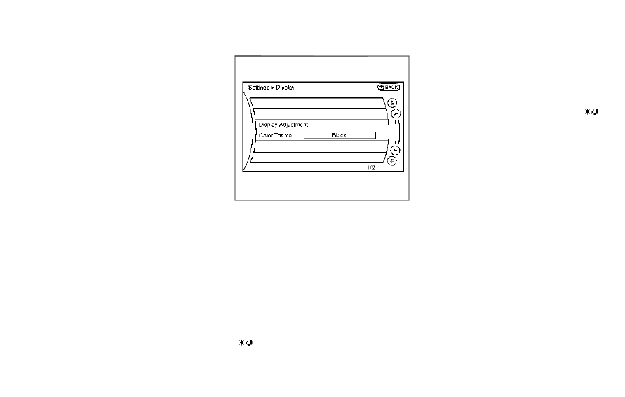
Display settings
The display as illustrated will appear
when pushing the SETTING button and
selecting the “Display” key.
Display Adjustment:
To adjust the display settings, select the
“Display Adjustment” key. The following
settings are available.
. Display
To turn off the screen, push the ENTER
button and turn the “Display” indicator off.
The other method is to push and hold the
“
OFF” button for more than 2 sec-
onds.
When any mode button is pushed with
the screen off, the screen turns on for
further operation. The screen will turn off
automatically 5 seconds after the opera-
tion is finished.
To turn on the screen, set this item to the
ON position, or push and hold the “
OFF” button.
. Brightness/Contrast/Background
Color
To adjust the brightness and contrast of
the screen, select the “Brightness” or
“Contrast” key.
Then, you can adjust the brightness and
contrast using the multi-function control-
ler.
For information on the “Background Col-
or” key, refer to the separate Navigation
System Owner’s Manual.
For Roadster models:
Depending on the driver’s seat position,
the display could be hard to read. Adjust
the brightness and contrast of the display
on the setting screen.
Color Theme:
Choose the theme color of the menu
screen from “Black”, “Blue” or “Red”.
Center display, heater, air conditioner, audio, phone and voice recognition systems
4-13