Nissan Altima L32. Manual - part 885
LAN
MAIN LINE BETWEEN DLC AND ABS CIRCUIT
LAN-69
< COMPONENT DIAGNOSIS >
[CAN SYSTEM (TYPE 3)]
C
D
E
F
G
H
I
J
K
L
B
A
O
P
N
COMPONENT DIAGNOSIS
MAIN LINE BETWEEN DLC AND ABS CIRCUIT
Diagnosis Procedure
INFOID:0000000004203901
INSPECTION PROCEDURE
1.
CHECK CONNECTOR
1. Turn the ignition switch OFF.
2. Disconnect the battery cable from the negative terminal.
3. Check the following terminals and connectors for damage, bend and loose connection (connector side
and harness side).
-
Harness connector M1
-
Harness connector E30
Is the inspection result normal?
YES
>> GO TO 2.
NO
>> Repair the terminal and connector.
2.
CHECK HARNESS CONTINUITY (OPEN CIRCUIT)
1. Disconnect the harness connectors M1 and E30.
2. Check the continuity between the data link connector and the harness connector.
Is the inspection result normal?
YES
>> GO TO 3.
NO
>> Repair the main line between the data link connector and the harness connector M1.
3.
CHECK HARNESS CONTINUITY (OPEN CIRCUIT)
1. Disconnect the connector of ABS actuator and electric unit (control unit).
2. Check the continuity between the harness connector and the ABS actuator and electric unit (control unit)
harness connector.
Is the inspection result normal?
YES (Present error)>>Check CAN system type decision again.
YES (Past error)>>Error was detected in the main line between the data link connector and the ABS actuator
and electric unit (control unit).
NO
>> Repair the main line between the harness connector E30 and the ABS actuator and electric unit
(control unit).
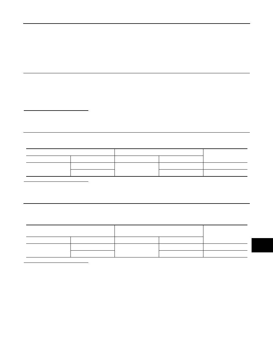
Data link connector
Harness connector
Continuity
Connector No.
Terminal No.
Connector No.
Terminal No.
M22
6
M1
15G
Existed
14
8G
Existed
Harness connector
ABS actuator and electric unit (control unit)
harness connector
Continuity
Connector No.
Terminal No.
Connector No.
Terminal No.
E30
15G
E26
26
Existed
8G
15
Existed