Nissan Altima L32. Manual - part 816
HAC-38
< COMPONENT DIAGNOSIS >
[AUTOMATIC AIR CONDITIONER]
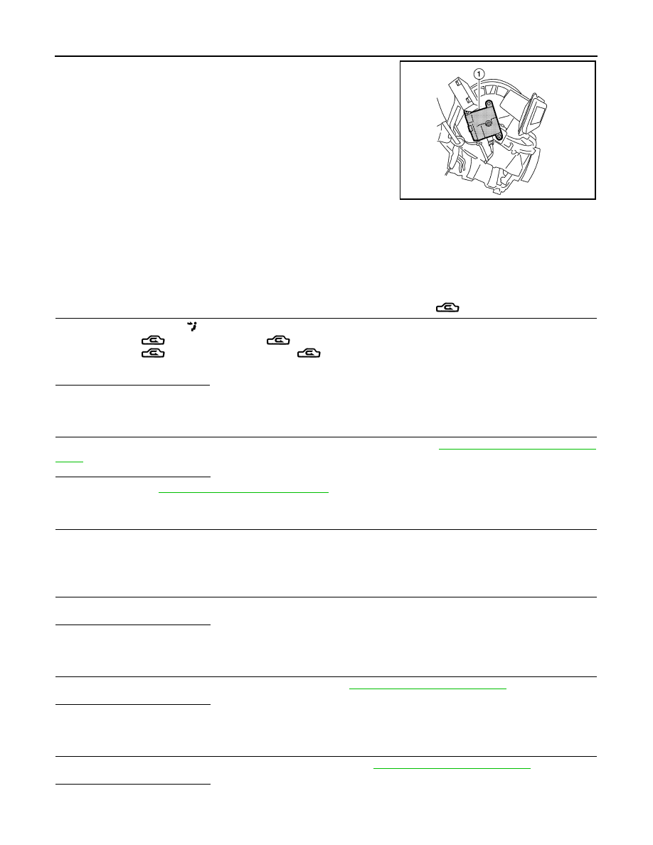
INTAKE DOOR MOTOR
The intake door motor (1) is attached to the blower unit. It rotates so
that air is drawn from inlets set by the front air control. Motor rotation
is conveyed to a lever which activates the intake door.
Diagnosis Procedure
INFOID:0000000004498208
SYMPTOM:
• Intake door does not change.
• Intake door motor does not operate normally.
INSPECTION FLOW
1.
CONFIRM SYMPTOM BY PERFORMING OPERATION CHECK - REC (
)
1. Press the vent mode.(
).
2. Press REC (
) switch. The REC (
) indicator should illumination.
3. Press REC (
) switch again. The REC (
) indicator should go out.
4. Listen for intake door position change (you should sound change slightly).
Can a symptom be duplicated?
YES
>> GO TO 3
NO
>> GO TO 2
2.
PERFORM COMPLETE OPERATIONAL CHECK
Perform a complete operational check and check for any symptoms. Refer to
HAC-5, "Description and Condi-
.
Is the inspection result normal?
YES
>> Refer to
HAC-83, "Symptom Matrix Chart"
.
NO
>> System OK.
3.
CHECK FOR SERVICE BULLETINS
Check for any service bulletins.
>> GO TO 4
4.
CHECK INTAKE DOOR MOTOR OPERATION
Check and verify intake door mechanism for smooth operation.
Is the inspection result normal?
YES
>> GO TO 5
NO
>> Repair as necessary.
5.
CHECK LAN SYSTEM CIRCUIT
Perform diagnostic procedure for the LAN system. Refer to
.
Is the inspection result normal?
YES
>> GO TO 6
NO
>> Repair as necessary.
6.
CHECK AMBIENT SENSOR CIRCUIT
Perform diagnostic procedure for the mode door motor. Refer to
.
Is the inspection result normal?
YES
>> GO TO 7
NO
>> Repair as necessary.
AWIIA0027ZZ