Nissan Altima L32. Manual - part 813


  Index      Nissan     Nissan Altima L32 (2007-2009 year) - Service and Repair Manual


Search            


Content   ..  811  812  813  814   ..


Nissan Altima L32. Manual - part 813


HAC-26

< FUNCTION DIAGNOSIS >

[AUTOMATIC AIR CONDITIONER]

SELF-DIAGNOSIS FUNCTION

10.

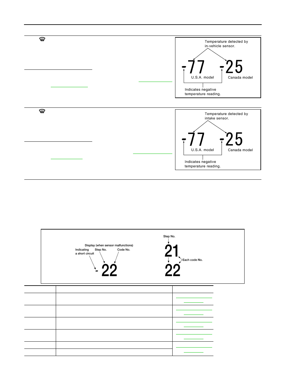
CHECK IN-VEHICLE SENSOR

Press 

 (DEF) switch for the second time. Temperature detected

by in-vehicle sensor is indicated on the display.

NOTE:

If the temperature indicated on the display greatly differs from the

actual temperature, check sensor circuit first, and then check sensor.
Is the inspection result normal?

YES

>> GO TO 11

NO

>> Go to In-vehicle Sensor Circuit. Refer to 

HAC-53, "Diag-

nosis Procedure"

.

11.

CHECK INTAKE SENSOR

Press 

 (DEF) switch for the third time. Temperature detected by

intake sensor is indicated on the display.

NOTE:

If the temperature indicated on the display greatly differs from the

actual temperature, check sensor circuit first, and then check sensor.
Is the inspection result normal?

YES

>> GO TO 12

NO

>> Go to Intake Sensor Circuit. Refer to 

HAC-59, "Diagno-

sis Procedure"

.

12.

CHECK MALFUNCTIONING SENSOR AND DOOR MOTOR

Refer to the following chart for malfunctioning code No.

(If two or more sensors and door motors malfunction, corresponding code Nos. indicates 1 second each.)

(If two door motors malfunction, corresponding code Nos. indicates 0.5 second each.)

*1: Perform self-diagnosis STEP-2 under sunshine.

When performing indoors, aim a light (more than 60W) at sunload sensor, otherwise code No. 25 will indicate

despite that sunload sensor is functioning properly.

NOTE:

Code 20 will be displayed if all sensor s and PBR(s) are OK.

PJIA0152E

PJIA0153E

Code No.

Malfunctioning sensor and door motor (Including circuits)

Reference page

21 / 

−21

Ambient sensor

HAC-50, "Diagnosis 

Procedure"

22 / 

−22

In-vehicle sensor

HAC-53, "Diagnosis 

Procedure"

24 / 

−24

Intake sensor

HAC-38, "Diagnosis 

Procedure"

25 / 

−25

Sunload sensor 

*1

HAC-38, "Diagnosis 

Procedure"

26 / 

−26

Air mix door motor PBR (LH)

HAC-35, "Diagnosis 

Procedure"

27 / 

−27

Air mix door motor PBR (RH)

AWIIA0015GB

SELF-DIAGNOSIS FUNCTION

HAC-27

< FUNCTION DIAGNOSIS >

[AUTOMATIC AIR CONDITIONER]

C

D

E

F

G

H

J

K

L

M

A

B

HAC

N

O

P

>> Inspection End

13.

CHECK MALFUNCTIONING DOOR MOTOR POSITION SWITCH

Mode and/or intake door motor PBR(s) is/are malfunctioning.

NOTE:

Code 30 will be displayed if all doors are OK.

(If two or more mode or intake door motors malfunction, corresponding code Nos. indicates 1 second each.)

*1: If mode door motor harness connector is disconnected, the following display pattern will appear.

31

→32→33→34→35→36 Return to 31

*2: If intake door motor harness connector is disconnected, the following display pattern will appear.

37

→38→39→Return to 37

>> Inspection End

Auxiliary Mechanism Trimmers

INFOID:0000000004498200

Refer to 

HAC-6, "Auxiliary Mechanism Trimmers"

.

Code No. 

*1 *2

Mode or intake door position

Reference page

31

VENT

Mode door motor

HAC-32, "Diagnosis Pro-

cedure"

32

B/L1

33

B/L2

34

AUTO D/F1

35

D/F2

36

DEF

37

FRE

Intake door motor

HAC-38, "Diagnosis Pro-

cedure"

38

20% FRE

39

REC

AWIIA0016GB

HAC-28

< COMPONENT DIAGNOSIS >

[AUTOMATIC AIR CONDITIONER]

LAN SYSTEM CIRCUIT

COMPONENT DIAGNOSIS

LAN SYSTEM CIRCUIT

Description

INFOID:0000000004498201

SYMPTOM: Mode door motor, intake door motor and/or air mix door motor does not operate normally.

Diagnosis Procedure

INFOID:0000000004498202

DIAGNOSIS PROCEDURE FOR LAN CIRCUIT

1.

CHECK POWER SUPPLY FOR DOOR MOTORS

1. Press ignition switch ON.

2. Check voltage between front air control connector M37 terminal

20 and ground.

Is the inspection result normal?

YES

>> GO TO 2

NO

>> Replace front air control. Refer to 

VTL-8, "Removal and

Installation"

.

2.

CHECK SIGNAL FOR DOOR MOTORS

Check voltage between front air control connector M37 terminal 3

and ground.

Is the inspection result normal?

YES

>> GO TO 3

NO

>> Replace front air control. Refer to 

VTL-8, "Removal and

Installation"

.

3.

CHECK POWER SUPPLY FOR MOTOR

AWIIA0050GB

Terminal

Voltage (V)

(Approx.)

(+)

(-)

Connector - Terminal

M37-20

Body ground

12V

AWIIA0017ZZ

Terminal

Voltage (V)

(Approx.)

(+)

(-)

Connector - Terminal

M37-3

Ground

5.5V

AWIIA0018ZZ

LAN SYSTEM CIRCUIT

HAC-29

< COMPONENT DIAGNOSIS >

[AUTOMATIC AIR CONDITIONER]

C

D

E

F

G

H

J

K

L

M

A

B

HAC

N

O

P

Check voltage between mode door motor connector M127 terminal 3

and ground, between air mix door motor (LH) connector M128 termi-

nal 3 and ground, between air mix door motor (RH) connector M129

terminal 3 and ground, and between intake door motor connector

M126 terminal 3 and ground.

Is the inspection result normal?

YES

>> GO TO 4

NO

>> Replace harness or connector.

4.

CHECK SIGNAL FOR MOTOR

Check voltage between mode door motor connector M127 terminal 1

and ground, between air mix door motor (LH) connector M128 termi-

nal 1 and ground, between air mix door motor (RH) connector M129

terminal 1 and ground, and between intake door motor connector

M58 terminal 1 and ground.

Is the inspection result normal?

YES

>> GO TO 5

NO

>> Replace harness or connector.

5.

CHECK MOTOR GROUND CIRCUIT

1. Press ignition switch OFF.

2. Disconnect door motor connectors.

3. Check continuity between mode door motor connector M127 ter-

minal 2 and ground, between air mix door motor (LH) connector

M128 terminal 2 and ground, between air mix door motor (RH)

connector M129 terminal 2 and ground, and between intake

door motor connector M126 terminal 2 and ground.

Door motors

Terminals

Voltage (V)

(Approx.)

(+)

(-)

Connector - Ter-

minal

Mode

M127-3

Body ground

12V

Air mix (LH)

M128-3

Air mix (RH)

M129-3

Intake

M126-3

AWIIA0019ZZ

Door motors

Terminals

Voltage (V)

(Approx.)

(+)

(-)

Connector - Terminal

Mode M127-1

Body ground

5.5V

Air mix (LH)

M128-1

Air mix (RH)

M129-1

Intake M126-1

AWIIA0020ZZ

Door motors

Terminals

Continuity

(+)

(-)

Connector - Terminal

Mode M127-2

Body ground

Yes

Air mix (LH)

M128-2

Air mix (RH)

M129-2

Intake

M126-2

WJIA0884E


Content   ..  811  812  813  814   ..