Nissan Altima L32. Manual - part 806


  Index      Nissan     Nissan Altima L32 (2007-2009 year) - Service and Repair Manual


Search            


Content   ..  804  805  806  807   ..


Nissan Altima L32. Manual - part 806


HA-44

< ON-VEHICLE REPAIR >

REFRIGERANT PRESSURE SENSOR

REFRIGERANT PRESSURE SENSOR

Removal and Installation for Refrigerant Pressure Sensor

INFOID:0000000004205510

REMOVAL

1. Discharge the refrigerant. Refer to 

HA-32, "HFC-134a (R-134a) Service Procedure"

.

2. Remove the front grille. Refer to 

EXT-17, "Removal and Installation"

.

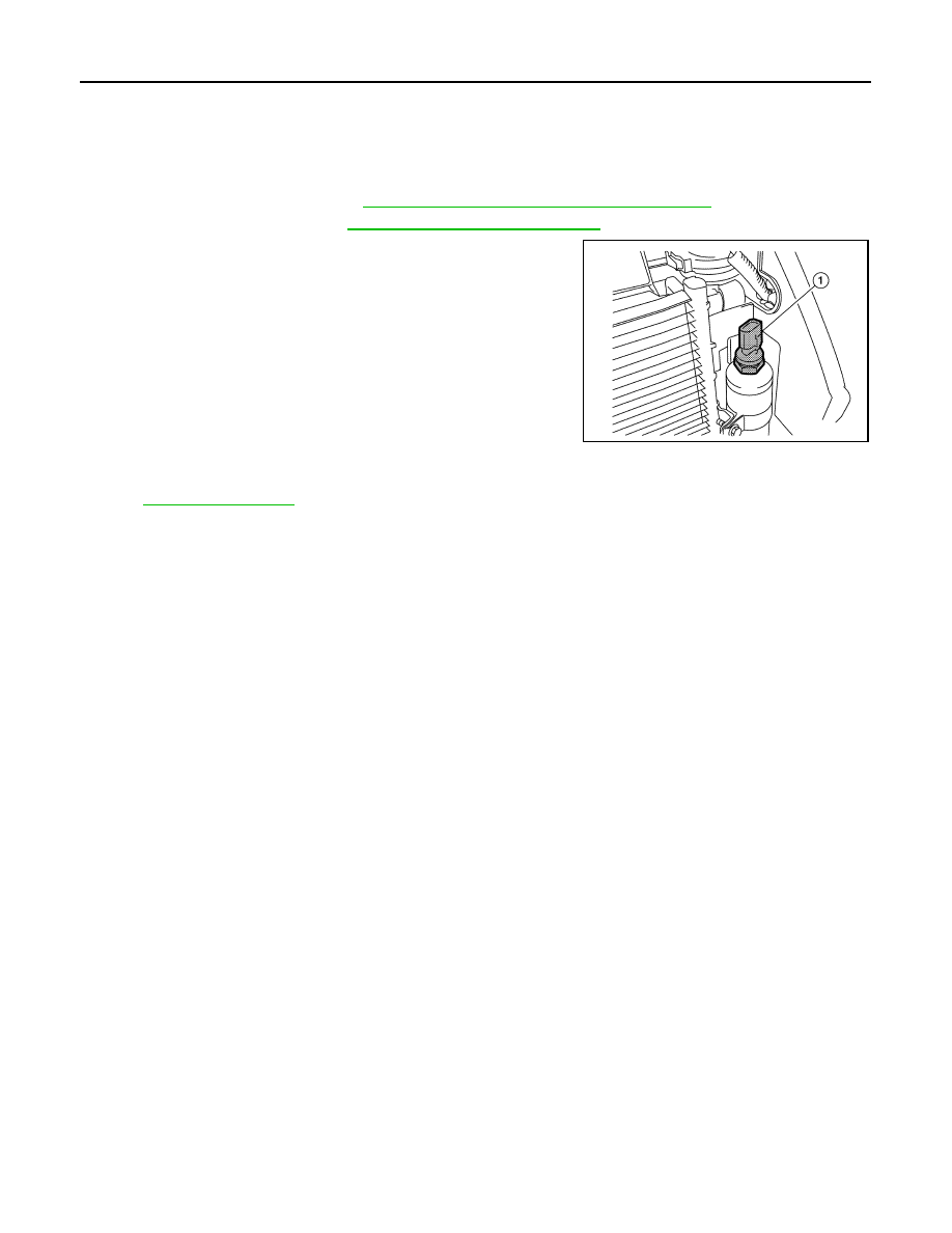
3. Disconnect the refrigerant pressure sensor connector and

remove the refrigerant pressure sensor (1) from the liquid tank

on the condenser.

CAUTION:

Do not damage the condenser fins.

INSTALLATION

Installation is in the reverse order of removal.

Refer to 

HA-31, "Component"

.

CAUTION:

Replace the O-ring of the refrigerant pressure sensor with a new one, then apply compressor oil to it

when installing it.

ALIIA0004ZZ

EXPANSION VALVE

HA-45

< ON-VEHICLE REPAIR >

C

D

E

F

G

H

J

K

L

M

A

B

HA

N

O

P

EXPANSION VALVE

Removal and Installation for Expansion Valve

INFOID:0000000004205511

REMOVAL

1. Discharge the refrigerant. Refer to 

HA-32, "HFC-134a (R-134a) Service Procedure"

.

2. Remove the strut tower bar. Refer to 

FSU-12, "Exploded View"

.

3. Remove the upper cowl. Refer to 

EXT-18, "Removal and Installation"

.

4. Remove the lower RH cowl.
5. Reposition the power steering reservoir aside without disconnecting the power steering hose.
6. Disconnect the A/C pipes from the expansion valve. Refer to 

HA-31, "Component"

.

CAUTION:

Cap or wrap the joint of the pipe with suitable material such as vinyl tape to avoid the entry of air.

7. Remove the expansion valve.

INSTALLATION

Installation is in the reverse order of removal.

CAUTION:

• Replace the O-rings with new ones, then apply compressor oil to them when installing them.

Expansion valve mounting bolts

: 2.9 - 5.0 N·m (0.29 - 0.51 kg-m, 26 - 44 in-lb)

HA-46

< SERVICE DATA AND SPECIFICATIONS (SDS) 

SERVICE DATA AND SPECIFICATIONS (SDS)

SERVICE DATA AND SPECIFICATIONS (SDS)

SERVICE DATA AND SPECIFICATIONS (SDS)

Service Data and Specification (SDS)

INFOID:0000000004205512

COMPRESSOR

OIL

REFRIGERANT

Model

VALEO

Type

DCS-171C

Displacement

171 cm

3

 (10.43 in

3

) / revolution

Cylinder bore 

× stroke

30.5 mm (1.201 in) x 21.4 mm (0.84 in)

Direction of rotation

Clockwise (viewed from drive end)

Drive belt

Poly V 6-grooves

Name

NISSAN A/C System Oil Type S or equivalent

Capacity

Total in system

150 m   (5.03 US fl oz, 5.3 lmp fl oz)

Compressor (service part) charging amount

Refer to 

HA-21, "Maintenance of Oil Quantity in Compressor"

.

Type

HFC-134a (R-134a)

Capacity

0.50 

± 0.025 kg (1.10 ± 0.055 lb)

HAC-1

VENTILATION, HEATER & AIR CONDITIONER

C

D

E

F

G

H

J

K

L

M

SECTION 

HAC

A

B

HAC

N

O

P

CONTENTS

HEATER & AIR CONDITIONING CONTROL SYSTEM

AUTOMATIC AIR CONDITIONER

BASIC INSPECTION  ....................................

4

DIAGNOSIS AND REPAIR WORKFLOW  ..........

4

Work Flow  .................................................................

4

INSPECTION AND ADJUSTMENT .....................

5

Description and Conditions .......................................

5

Operational Check  ....................................................

5

Auxiliary Mechanism Trimmers  .................................

6

FUNCTION DIAGNOSIS ...............................

9

FUNCTION INFORMATION  ................................

9

Component Part Location  .........................................

9

Component’s Role ...................................................

11

REFRIGERATION SYSTEM  ..............................

13

Refrigerant Cycle  ....................................................

13

Refrigerant System Protection ................................

13

AUTOMATIC AIR CONDITIONER SYSTEM  .....

14

System Diagram ......................................................

14

System Description  .................................................

14

Component Part Location  .......................................

20

Component Description ...........................................

20

DIAGNOSIS SYSTEM (ECM) .............................

21

CONSULT-III Function  ............................................

21

SELF-DIAGNOSIS FUNCTION ..........................

22

Diagnosis Description  .............................................

22

Auxiliary Mechanism Trimmers  ...............................

27

COMPONENT DIAGNOSIS .........................

28

LAN SYSTEM CIRCUIT  .....................................

28

Description ..............................................................

28

Diagnosis Procedure ...............................................

28

MODE DOOR MOTOR  .......................................

31

Description ..............................................................

31

Diagnosis Procedure  ...............................................

32

AIR MIX DOOR MOTOR  ...................................

34

Description ...............................................................

34

Diagnosis Procedure  ...............................................

35

INTAKE DOOR MOTOR  ...................................

37

Description ...............................................................

37

Diagnosis Procedure  ...............................................

38

BLOWER MOTOR  ............................................

40

Description ...............................................................

40

Component Function Check  ....................................

41

Diagnosis Procedure  ...............................................

42

MAGNET CLUTCH  ...........................................

46

Description ...............................................................

46

Component Function Check  ....................................

46

Diagnosis Procedure  ...............................................

47

AMBIENT SENSOR  ..........................................

50

Description ...............................................................

50

Diagnosis Procedure  ...............................................

50

Component Inspection .............................................

51

IN-VEHICLE SENSOR  ......................................

53

Component Description  ...........................................

53

Diagnosis Procedure  ...............................................

53

Component Inspection .............................................

55

SUNLOAD SENSOR .........................................

56

Description ...............................................................

56

Diagnosis Procedure  ...............................................

56

Component Inspection .............................................

57

INTAKE SENSOR  .............................................

59

Description ...............................................................

59

Diagnosis Procedure  ...............................................

59

Component Inspection .............................................

60

POWER SUPPLY AND GROUND CIRCUIT 
FOR FRONT AIR CONTROL ............................

61

Description ...............................................................

61


Content   ..  804  805  806  807   ..