Nissan Altima L32. Manual - part 767
 

  Index      Nissan     Nissan Altima L32 (2007-2009 year) - Service and Repair Manual


Search            


Content   ..  765  766  767  768   ..


Nissan Altima L32. Manual - part 767


FUEL TANK

FL-13

< ON-VEHICLE REPAIR >

C

D

E

F

G

H

I

J

K

L

M

A

FL

N

P

O

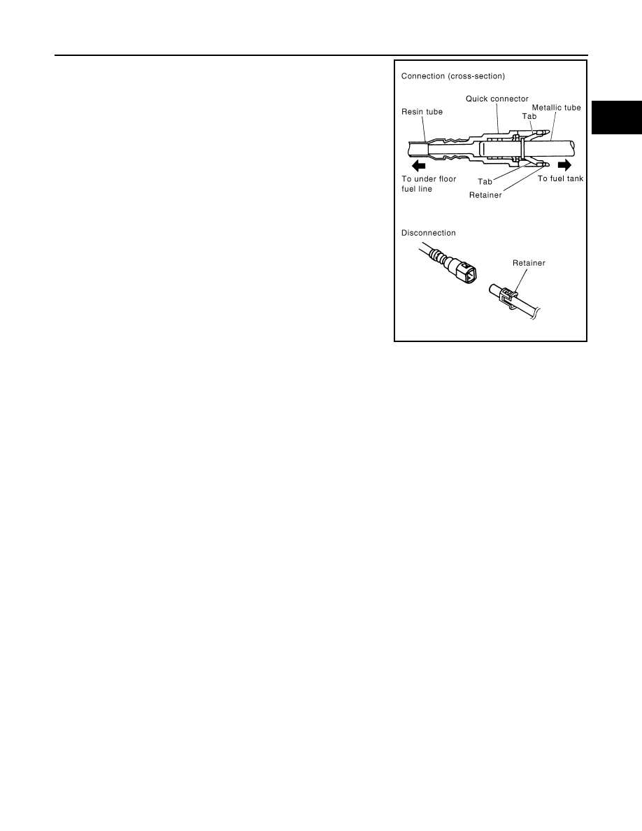
- Visually confirm that the two retainer tabs are connected to the

quick connector. 

INSPECTION AFTER INSTALLATION

Use the following procedure to check for fuel leaks.
1. Turn the ignition switch ON (without starting the engine). Then check the connections for fuel leaks by

applying fuel pressure to the fuel piping.

2. Run the engine and check for fuel leaks at the fuel system tube and hose connections.

Inspection

INFOID:0000000004205621

INSPECTION  AFTER  INSTALLATION

Use the following procedure to check for fuel leaks.
1. Turn ignition switch “ON” (with engine stopped), and check connections for leakage by applying fuel pres-

sure to fuel piping.

2. Start engine and rev it up and make sure there are no fuel leaks at the fuel system tube and hose connec-

tions.

PBIC0199E

FL-14

< SERVICE DATA AND SPECIFICATIONS (SDS) 

SERVICE DATA AND SPECIFICATIONS (SDS)

SERVICE DATA AND SPECIFICATIONS (SDS)

SERVICE DATA AND SPECIFICATIONS (SDS)

Fuel Tank

INFOID:0000000004205622

Standard and Limit

Fuel tank capacity

Approx. 76.6   (20 US gal, 16-5/8 Imp gal)

Fuel recommendation

Refer to 

MA-12, "Fluids and Lubricants"

FSU-1

SUSPENSION

C

D

F

G

H

I

J

K

L

M

SECTION 

FSU

A

B

FSU

N

O

P

CONTENTS

FRONT SUSPENSION

SYMPTOM DIAGNOSIS  ...............................

2

NOISE, VIBRATION AND HARSHNESS 
(NVH) TROUBLESHOOTING  .............................

2

NVH Troubleshooting Chart  ......................................

2

PRECAUTION ...............................................

3

PRECAUTIONS ...................................................

3

Precaution for Supplemental Restraint System 
(SRS) "AIR BAG" and "SEAT BELT PRE-TEN-
SIONER" .................................................................
..

3

Necessary for Steering Wheel Rotation After Bat-
tery Disconnect  .......................................................
..

3

Service Notice or Precautions ...................................

3

PREPARATION ............................................

5

PREPARATION ...................................................

5

Special Service Tool  .................................................

5

Commercial Service Tool  ..........................................

6

ON-VEHICLE MAINTENANCE .....................

7

FRONT SUSPENSION ASSEMBLY  ...................

7

Inspection and Adjustment ........................................

7

ON-VEHICLE REPAIR ..................................

9

FRONT COIL SPRING AND STRUT  .................

9

Removal and Installation  ..........................................

9

TRANSVERSE LINK .........................................

10

Removal and Installation  .........................................

10

FRONT STABILIZER  ........................................

11

Removal and Installation  .........................................

11

REMOVAL AND INSTALLATION ...............

12

FRONT SUSPENSION ASSEMBLY .................

12

Exploded View .........................................................

12

Removal and Installation  .........................................

13

DISASSEMBLY AND ASSEMBLY ..............

14

FRONT COIL SPRING AND STRUT  ................

14

Disassembly and Assembly .....................................

14

Inspection ................................................................

15

SERVICE DATA AND SPECIFICATIONS 
(SDS) ............................................................

16

SERVICE DATA AND SPECIFICATIONS 
(SDS) .................................................................

16

Wheel Alignment (Unladen*)  ...................................

16

Ball Joint  ..................................................................

17

Wheelarch Height (Unladen*1) ................................

17

FSU-2

< SYMPTOM DIAGNOSIS >

NOISE, VIBRATION AND HARSHNESS (NVH) TROUBLESHOOTING

SYMPTOM DIAGNOSIS

NOISE, VIBRATION AND HARSHNESS (NVH) TROUBLESHOOTING

NVH Troubleshooting Chart

INFOID:0000000004205262

Use the chart below to help you find the cause of the symptom. If necessary, repair or replace these parts.

×: Applicable

Reference page

FSU-12

FSU-15

FSU-12

FS

U-7

FS

U-7

WT

-61, "

NVH T

rou

bl

es

ho

ot

ing

 Cha

rt

"

WT

-61, "

NVH T

rou

bl

es

ho

ot

ing

 Cha

rt

"

FAX-2, "

NVH T

rou

ble

sh

oo

tin

g Chart

"

BR-6, "

NVH T

rou

bl

es

ho

oti

ng

 Cha

rt

"

ST

-3, "

NVH T

rou

bl

es

ho

ot

in

g Cha

rt

"

Possible cause and SUSPECTED PARTS

Im

prop

er in

st

a

lla

tion

, lo

os

en

es

s

Sh

oc

k a

b

so

rb

er de

fo

rm

at

io

n,

 d

a

m

a

ge

 or d

e

flec

tion

Bu

sh

in

g o

m

o

un

ting

 de

te

riora

tio

n

Part

s interference

S

p

ring

 fa

tig

ue

Su

sp

en

si

on

 lo

os

en

es

s

Inc

orre

ct

 whe

el

 al

ig

nm

en

t

S

ta

bi

liz

er ba

fa

tig

ue

TIRES

ROA

D

 WHEEL

DRIVE SHA

FT AND W

H

EEL 

HU

B

BRAKES

STEERI

N

G

Symptom

Noise

×

×

×

×

×

×

×

×

×

×

×

Shake

×

×

×

×

×

×

×

×

×

×

Vibration

×

×

×

×

×

×

×

×

Shimmy

×

×

×

×

×

×

×

×

×

Shudder

×

×

×

×

×

×

×

Poor quality ride or handling

×

×

×

×

×

×

×

×

×


Content   ..  765  766  767  768   ..