Nissan Altima L32. Manual - part 759
FRONT WHEEL HUB AND KNUCKLE
FAX-9
< ON-VEHICLE REPAIR >
C
E
F
G
H
I
J
K
L
M
A
B
FAX
N
O
P
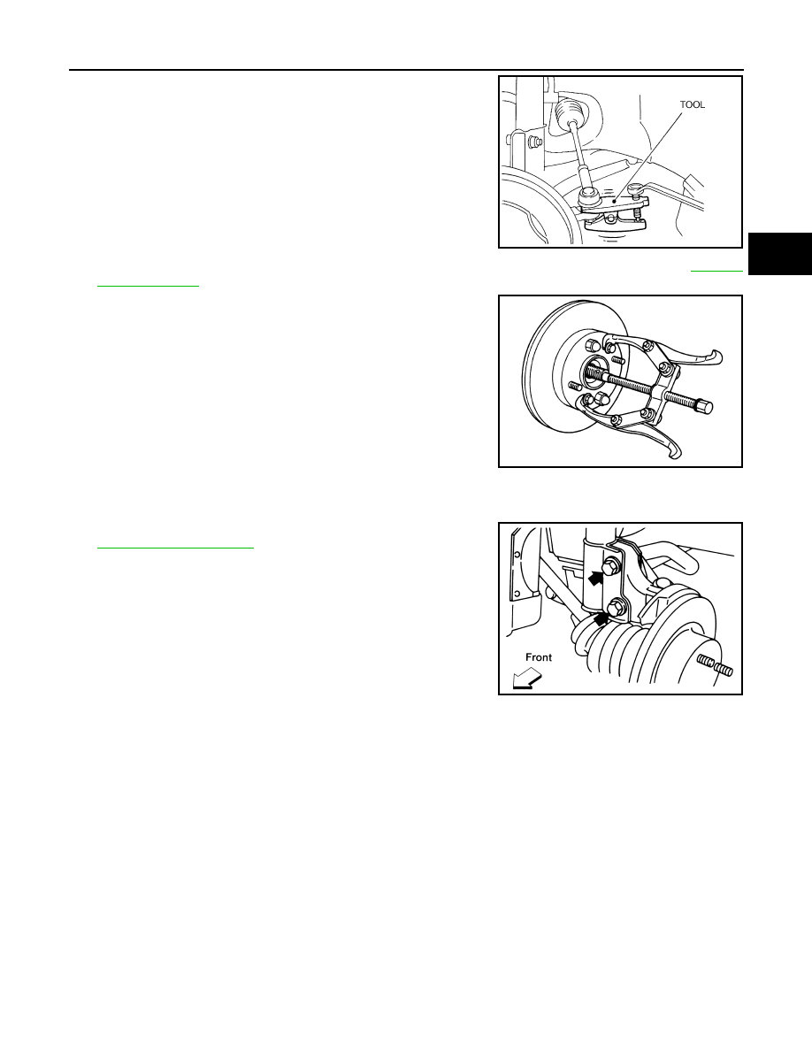
7. Disconnect the outer tie-rod end from steering knuckle using
Tool. Be careful not to damage ball joint boot.
CAUTION:
To prevent damage to threads and to prevent Tool from
coming off suddenly, temporarily tighten mounting nut.
8. Remove transverse link and steering knuckle pinch bolt and nut using power tool. Refer to
9. Remove wheel hub and bearing assembly from drive shaft using
a puller or suitable tool.
CAUTION:
• When removing wheel hub and bearing assembly, do not
apply an excessive angle to drive shaft joint. Also be care-
ful not to excessively extend slide joint.
• Support drive shaft when removing.
10. Remove wheel hub and bearing assembly bolts using power tool.
11. Remove splash guard and wheel hub and bearing assembly from steering knuckle.
12. Remove the lower strut bolts and nuts using power tool. Refer to
.
13. Remove steering knuckle from vehicle.
INSPECTION AFTER REMOVAL
Check for deformity, cracks and damage on each part, replace if necessary.
Ball Joint Inspection
• Check for boot breakage, axial looseness, and torque of transverse link ball joint and repair as necessary.
INSTALLATION
Installation is in the reverse order of removal.
CAUTION:
Do not reuse non-reusable parts.
• When installing wheel hub and bearing assembly to steering knuckle, align cutout in toner ring cover with
wheel sensor mounting hole in steering knuckle.
Tool number
: HT72520000 (J-25730-A)
WGIA0101E
SDIA0972J
AFA047