Nissan Altima L32. Manual - part 662
EM-184
< ON-VEHICLE REPAIR >
[VQ35DE]
CAMSHAFT
• When out of the specified range, replace either or both camshaft and cylinder head.
NOTICE:
Inner diameter of camshaft bracket is manufactured together with cylinder head. Replace the whole cylinder
head assembly.
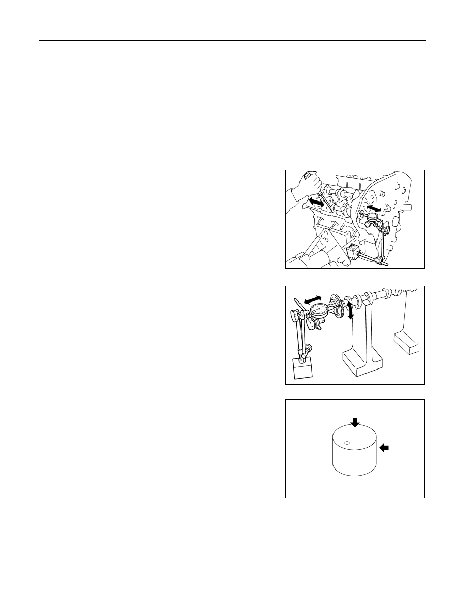
Camshaft End Play
1. Install the camshaft in the cylinder head.
2. Install dial gauge in thrust direction on front end of camshaft.
Measure end play when camshaft is moved forward/backward
(in direction to axis) as shown.
• If out of the specified range, replace with new camshaft and mea-
sure again.
• If out of the specified range again, replace with new cylinder head.
Camshaft Sprocket Runout
1. Put V-block on precise flat bed and support No. 2 and No. 4 jour-
nal of camshaft as shown.
2. Install camshaft sprocket on camshaft.
3. Measure camshaft sprocket runout.
4. If sprocket runout exceeds the limit, replace camshaft sprocket.
Valve Lifter
• Check if the surface of the valve lifter has any excessive wear or
cracks, replace as necessary.
Valve Lifter Clearance
Outer Diameter of Valve Lifter
Standard
No.1
: 0.045 - 0.086 mm (0.0018 - 0.0034 in)
Standard
No.2, 3, 4
: 0.035 - 0.076 mm (0.0014 - 0.0030 in)
Limit
: 0.15 mm (0.0059 in)
Standard
: 0.115 - 0.188 mm (0.0045 - 0.0074 in)
Limit
: 0.24 mm (0.0094 in)
SEM864E
Runout
: Less than 0.15 mm (0.0059 in)
PBIC0930E
KBIA0182E