Nissan Altima L32. Manual - part 648


  Index      Nissan     Nissan Altima L32 (2007-2009 year) - Service and Repair Manual


Search            


Content   ..  646  647  648  649   ..


Nissan Altima L32. Manual - part 648


EM-128

< ON-VEHICLE MAINTENANCE >

[VQ35DE]

COMPRESSION PRESSURE

COMPRESSION PRESSURE

On-Vehicle Service

INFOID:0000000004202157

CHECKING COMPRESSION PRESSURE

1. Run the engine until it reaches normal operating temperature.
2. Turn the ignition switch to OFF.
3. Release fuel pressure and leave the fuel pump electrically disconnected.

Refer to 

EC-1579, "Inspection"

4. Remove all six spark plugs.

Refer to 

EM-119, "Removal and Installation"

.

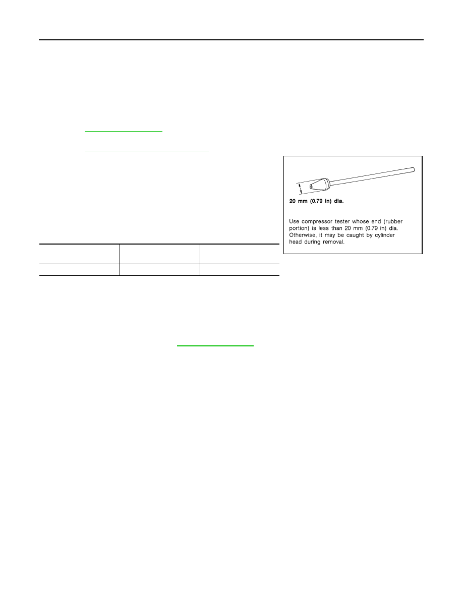
5. Attach a compression tester to No. 1 cylinder.
6. Depress accelerator pedal fully to keep the electric throttle con-

trol actuator butterfly-valve wide open to maximize air intake

flow.

7. Crank the engine and record the highest gauge indication.
8. Repeat the measurement on each cylinder (steps 5 - 7).

• Always use a fully-charged battery to obtain specified

engine speed.

Unit: kPa (kg/cm

2

, psi)/rpm

9. If compression in one or more cylinders is low:
a. Pour a small amount of engine oil into cylinders through the spark plug holes.
b. Retest compression (steps 5 - 8).
• If adding oil helps raise compression pressure, then the piston rings may be worn or damaged. If so,

replace piston rings after checking piston.

• If the pressure stays low, a valve may be sticking or is seating improperly. Inspect and repair the

valve and/or valve seat. Refer to 

EM-229, "Camshaft"

. If the valve and/or valve seat is damaged

excessively, replace as necessary.

• If compression stays low in two or more cylinders that are next to each other:

- The cylinder head gasket may be leaking.

- Both cylinders may have valve component damage. Inspect and repair as necessary.

Standard

Minimum

Difference limit between 

cylinders

1,275 (13.0, 185)/300

981 (10.0, 142)/300

98 (1.0, 14)/300

SEM387C

AIR CLEANER AND AIR DUCT

EM-129

< ON-VEHICLE REPAIR >

[VQ35DE]

C

D

E

F

G

H

I

J

K

L

M

A

EM

N

P

O

ON-VEHICLE REPAIR

AIR CLEANER AND AIR DUCT

Removal and Installation

INFOID:0000000004202158

REMOVAL

1. Remove front air duct.
2. Disconnect the tube clamp at the electric throttle control actuator and at the air duct hose.
3. Remove air duct hose.
4. Disconnect mass air flow sensor.
5. Remove mass air flow sensor from air cleaner assembly, as necessary.

CAUTION:

Handle mass air flow sensor with care.

• Do not shock it.

• Do not disassemble it.

• Do not touch its sensor.

6. Remove air cleaner assembly.

INSTALLATION

Installation is in the reverse order of removal.

ALBIA0497ZZ

1.

Air duct hose

2.

Duct sub-cover

3.

Front air duct

4.

Air cleaner assembly

5.

Grommets

6.

Air cleaner mounting bracket

7.

Bracket

8.

Mass air flow sensor

A. To electric throttle control actuator

EM-130

< ON-VEHICLE REPAIR >

[VQ35DE]

INTAKE MANIFOLD COLLECTOR

INTAKE MANIFOLD COLLECTOR

Removal and Installation

INFOID:0000000004202159

REMOVAL

WARNING:

• To avoid the danger of being scalded, never drain the coolant when the engine is hot.

• The gasket for intake manifold collector (upper) is secured together with intake manifold collector

(lower) bolt. Thus, when replacing only the upper gasket the lower gasket must also be replaced.

1. Release fuel pressure. Refer to 

EC-1579, "Inspection"

.

2. Remove the cowl top. Refer to 

EXT-18, "Removal and Installation"

.

3. Remove the engine cover, using power tool.
4. Remove air cleaner assembly and fresh air intake tube as an assembly. Refer to 

EM-129, "Removal and

Installation"

.

5. Partially drain the coolant when the engine is cool. Refer to 

CO-35, "Changing Engine Coolant"

.

AWBIA0428GB

1.

Power valve (RH)

2.

Intake manifold collector

3.

Gasket

4.

Power valve (LH)

5.

Electric throttle control actuator

INTAKE MANIFOLD COLLECTOR

EM-131

< ON-VEHICLE REPAIR >

[VQ35DE]

C

D

E

F

G

H

I

J

K

L

M

A

EM

N

P

O

6. If necessary, remove the electric throttle control actuator bolts in

the reverse order as shown and remove the electric throttle con-

trol actuator.

CAUTION:

• Handle carefully to avoid any shock to the electric throttle

control actuator.

• Do not disassemble.

7. If necessary, remove power valve bolts in the reverse order as

shown and remove the power valves.

8. Disconnect the following:

• Power brake booster vacuum hose

• Coolant hoses from the electric throttle control actuator

• Fuel injector electrical connectors

• PCV hose

• Electric throttle control actuator electrical connector

• EVAP canister purge hose

CAUTION:

• Cover any engine openings to avoid the entry of any foreign material.

9. Remove the EVAP canister purge volume solenoid valve bracket bolt. Position the valve aside.
10. Loosen the intake manifold collector bolts in the order as shown

using power tool, and remove the intake manifold collector and

gasket.

11. If necessary remove the following components:

• VIAS control solenoid valve

SEM711G

ALBIA0229ZZ

ALBIA0230ZZ

ALBIA0228ZZ


Content   ..  646  647  648  649   ..