Nissan Altima L32. Manual - part 634


  Index      Nissan     Nissan Altima L32 (2007-2009 year) - Service and Repair Manual


Search            


Content   ..  632  633  634  635   ..


Nissan Altima L32. Manual - part 634


EM-72

< REMOVAL AND INSTALLATION >

[QR25DE]

ENGINE ASSEMBLY

REMOVAL AND INSTALLATION

ENGINE ASSEMBLY

Removal and Installation

INFOID:0000000004202133
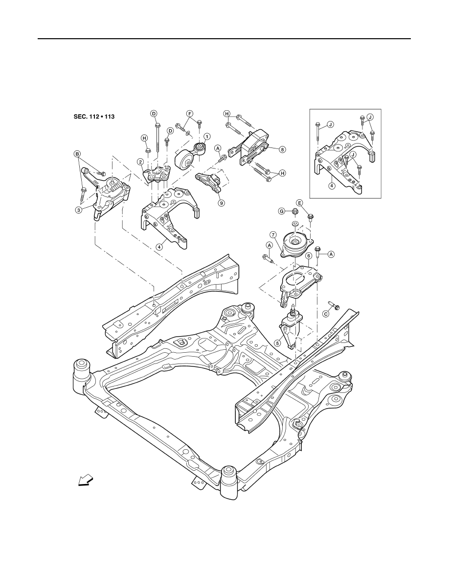
ALBIA0550ZZ

1.

RH engine mount torque rod

2.

RH engine support bracket 

3.

RH engine mounting insulator 

4.

RH engine mounting bracket

5.

Transmission mounting bracket

6.

LH engine mounting bracket

7.

LH engine mounting insulator

8.

Rear engine mount torque rod

9.

Rear engine mount torque rod bracket

A. 40 N·m (4.1 kg-m, 30 ft-lb)

B. 41 N·m (4.2 kg-m, 30 ft-lb)

C. 45 N·m (4.6 kg-m, 33 ft-lb)

D. 50 N·m (5.1 kg-m, 37 ft-lb)

E. 60 N·m (6.1 kg-m, 44 ft-lb)

F.

85 N·m (8.7 kg-m, 63 ft-lb)

ENGINE ASSEMBLY

EM-73

< REMOVAL AND INSTALLATION >

[QR25DE]

C

D

E

F

G

H

I

J

K

L

M

A

EM

N

P

O

WARNING:

• Place chocks at the front and back of the rear wheels.

• For engines not equipped with slingers, attach proper slingers and bolts as described in the Parts

Catalog.

CAUTION:

• Do not start working until the exhaust system and coolant are cool.

• If items or work required are not covered by the engine main body section, follow the applicable pro-

cedures.

• Use the correct supporting points for lifting and jacking. Refer to 

GI-33, "Garage Jack and Safety

Stand"

.

• In removing the drive shaft, be careful not to damage the grease seals on the transaxle.

REMOVAL

1. Remove engine cover using power tool.
2. Release fuel pressure. Refer to 

EC-550, "Inspection"

 (California), 

EC-1038, "Inspection"

 (Except Califor-

nia). 

3. Disconnect the negative battery terminal. Refer to 

PG-68, "Removal and Installation"

 (Coupe models),

PG-139, "Removal and Installation"

 (Sedan models).

4. Disconnect the fuel rail at the fuel hose quick connector (engine side). Refer to 

EM-26

 .

5. Drain the engine oil. Refer to 

LU-10, "Changing Engine Oil"

.

6. Drain the engine coolant. Refer to 

CO-12, "Changing Engine Coolant"

.

7. Remove the engine undercover using power tools.
8. Drain power steering fluid. Refer to 

ST-8, "Draining"

.

9. Drain transaxle fluid. Refer to 

TM-17, "Draining"

 (M/T), 

TM-417, "Changing CVT Fluid"

 (CVT).

10. Remove hood assembly. Refer to 

DLK-208, "HOOD ASSEMBLY : Removal and Installation"

.

11. Remove the air duct and air cleaner case assembly. Refer to 

EM-25, "Removal and Installation"

.

12. Remove battery tray.
13. Remove the ECM bracket.
14. Remove cowl top. Refer to 

EXT-18, "Removal and Installation"

 (Coupe models), 

EXT-39, "Removal and

Installation"

 (Sedan models).

15. Remove strut brace. Refer to 

FSU-12, "Exploded View"

.

16. Disconnect and set aside the IPDM/ER and remove the IPDM/ER bracket. Refer to 

PCS-48, "Removal

and Installation"

.

17. Remove upper and lower radiator hoses (engine side)
18. Remove CVT cooler lines (CVT models).
19. Disconnect fuel lines
20. Remove the engine coolant reservoir tank.
21. Disconnect the heater hoses.
22. Remove front LR and RH wheels and tires. Refer to 

WT-66, "Adjustment"

.

23. Remove the engine under covers and splash shield using power tool.
24. Remove the lower side bolt of the lower steering shaft assembly. 
25. Remove rear cover plate.
26. Remove the torque converter bolts (CVT models).
27. Remove the rear engine mount torque rod.
28. Remove front exhaust tube. Refer to 

EX-5, "Exploded View"

.

29. Remove the left and right drive shafts. Refer to 

FAX-11,

"Removal and Installation (Left Side)"

FAX-12, "Removal and

Installation (Right Side)"

.

30. Remove the front suspension member. Refer to 

FSU-13,

"Removal and Installation"

.

G. 90 N·m (9.2 kg-m, 66 ft-lb)

H. 103 N·m (11 kg-m, 76 ft-lb)

J.

Follow installation procedure

Front

SGIA0844E

EM-74

< REMOVAL AND INSTALLATION >

[QR25DE]

ENGINE ASSEMBLY

31. Dismount the A/C compressor with piping connected and secure with wire to the radiator support.
32. Dismount the power steering pump with piping connected and position it aside with wire.
33. Disconnect the clutch operating cylinder fluid line (M/T models). Refer to 

CL-12, "Removal and Installa-

tion"

.

34. Disconnect the transaxle shift controls.
35. Install engine slingers into front left cylinder head (A) and rear

right cylinder head (B).

• Use generator bracket bolt holes for the front slinger.

• Use the proper slingers and bolts as described in the Parts

Catalog.

36. Support engine and transaxle assembly with engine lifting equipment from the top with the vehicle raised

on a hoist.

37. Remove the RH engine mount torque rod, RH engine support bracket and RH engine mounting insulator

and bracket.

38. Remove LH transaxle mounting insulator through-bolts.
39. Lower the engine and transaxle assembly from the engine compartment using suitable tool.

CAUTION:

• Before and during this procedure, always check if any harnesses are left connected.

• Avoid any damage to, or any oil/grease smearing or spills onto the engine mounting insulators.

40. Remove the starter motor. Refer to 

STR-25, "Removal and Installation"

 (M/T), 

STR-25, "Removal and

Installation"

 (CVT).

41. Separate engine and transaxle. Refer to 

TM-26, "Exploded View"

 (M/T), 

TM-447, "Exploded View"

 (CVT).

INSTALLATION

Installation is in the reverse order of removal.

NOTE:

Tighten the transmission mounting bolts to specification. Refer to 

TM-26, "Removal and Installation"

 (M/T),

TM-447, "Removal and Installation"

 (CVT).

• Do not allow oil to get on mounting insulators. Be careful not to damage mounting insulators.

• If parts have a direction mark (arrow) this indicates front of the vehicle, and the parts must be installed

according to the identification mark.

• Install the RH engine mounting bracket bolts in the following steps:

- First install bolts (A) and (B) loosely.

- Install and tighten the five RH engine mounting bracket bolts to

specification in the order as shown.

-

: Front

INSPECTION AFTER INSTALLATION

• Before starting engine, check oil/fluid levels including engine coolant and engine oil. If less than required

quantity, fill to the specified level. Refer to 

MA-12, "Fluids and Lubricants"

.

• Use procedure below to check for fuel leakage.

• Turn ignition switch ON (with engine stopped). With fuel pressure applied to fuel piping, check for fuel leak-

age at connection points.

• Start engine. With engine speed increased, check again for fuel leakage at connection points.

• Run engine to check for unusual noise and vibration.

Slinger bolts - front

: 48 N·m (4.9 kg-m, 35 ft-lb)     

Slinger bolts - rear

: 28 N·m (2.8 kg-m, 21 ft-lb) 

ALBIA0207ZZ

RH engine mounting bracket bolt : 48.2 N·m (4.9 kg-m, 

36 ft-lb)

ALBIA0541ZZ

ENGINE ASSEMBLY

EM-75

< REMOVAL AND INSTALLATION >

[QR25DE]

C

D

E

F

G

H

I

J

K

L

M

A

EM

N

P

O

• Warm up engine thoroughly to make sure there is no leakage of fuel, exhaust gas, or any oils/fluids including

engine oil and engine coolant.

• Bleed air from passages in lines and hoses, such as in cooling system.

• After cooling down engine, again check oils/fluids including engine oil and engine coolant. Refill to specified

level, if necessary.

• Summary of the inspection items:

*Transmission/transaxle/CVT fluid, power steering fluid, brake fluid, etc.

Item

Before starting engine

Engine running

After engine stopped

Engine coolant

Level

Leakage

Level

Engine oil

Level

Leakage

Level

Other oils and fluids*

Level

Leakage

Level

Fuel

Leakage

Leakage

Leakage

Exhaust gas

Leakage


Content   ..  632  633  634  635   ..