Nissan Altima L32. Manual - part 460
 

  Index      Nissan     Nissan Altima L32 (2007-2009 year) - Service and Repair Manual


Search            


Content   ..  458  459  460  461   ..


Nissan Altima L32. Manual - part 460


FUEL PUMP

EC-961

< COMPONENT DIAGNOSIS >

[QR25DE EXCEPT FOR CALIFORNIA]

C

D

E

F

G

H

I

J

K

L

M

A

EC

N

P

O

Is the inspection result normal?

YES

>> GO TO 13.

NO

>> GO TO 7.

6.

DETECT MALFUNCTIONING PART

Check the following.

• Harness connectors E29, B10

• IPDM E/R connector F10

• Harness for open or short between IPDM E/R and condenser-I

>> Repair open circuit or short to power in harness or connectors.

7.

CHECK CONDENSER GROUND CIRCUIT

1. Turn ignition switch OFF.

2. Disconnect dropping resistor harness connector.

3. Check the continuity between condenser-I harness connector and ground.

4. Also check harness for short to ground and short to power.
Is the inspection result normal?

YES

>> GO TO 8.

NO

>> Repair open circuit or short to power in harness or connectors.

8.

CHECK CONDENSER-1

Refer to 

EC-962, "Component Inspection (Condenser-1)"

.

Is the inspection result normal?

YES

>> GO TO 9.

NO

>> Replace condenser-1.

9.

CHECK FUEL PUMP POWER SUPPLY CIRCUIT-III

1. Disconnect “fuel level sensor unit and fuel pump” harness connector.

2. Check the continuity between IPDM E/R harness connector and “fuel level sensor unit and fuel pump” and

ground. 

Is the inspection result normal?

YES

>> GO TO 11.

NO

>> GO TO 10.

10.

DETECT MALFUNCTIONING PART

Check the following.

• Harness connector E29, B10

• Harness for open or short between “fuel level sensor unit and fuel pump” and IPDM E/R

• Harness for open or short between “fuel level sensor unit and fuel pump” and ground

>> Repair open circuit or short to power in harness or connectors.

11.

CHECK FUEL PUMP GROUND CIRCUIT

1. Check the continuity between “fuel level sensor unit and fuel pump” and ground. 

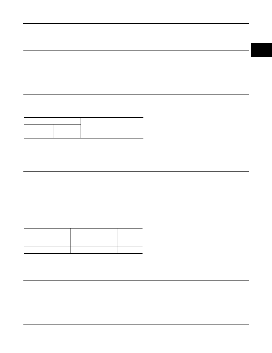
Condenser-I

Ground

Continuity

Connector

Terminal

B17

2

Ground

Existed

IPDM E/R

Fuel level sensor unit and 

fuel pump

Continuity

Connector

Terminal

Connector

Terminal

E18

13

B42

1

Existed

EC-962

< COMPONENT DIAGNOSIS >

[QR25DE EXCEPT FOR CALIFORNIA]

FUEL PUMP

2. Also heck harness for short to power. 
Is the inspection result normal?

YES

>> GO TO 12.

NO

>> Repair open circuit or short to power in harness or connectors.

12.

CHECK FUEL PUMP

Refer to 

EC-962, "Component Inspection (Fuel Pump)"

.

Is the inspection result normal?

YES

>> GO TO 13.

NO

>> Replace fuel pump.

13.

CHECK INTERMITTENT INCIDENT

Refer to 

GI-42, "Intermittent Incident"

.

Is the inspection result normal?

YES

>> Replace IPDM E/R.

NO

>> Repair or replace harness or connectors.

Component Inspection (Fuel Pump)

INFOID:0000000004349955

1.

CHECK FUEL PUMP

1. Turn ignition switch OFF.

2. Disconnect “fuel level sensor unit and fuel pump” harness connector.

3. Check resistance between “fuel level sensor unit and fuel pump”

terminals as follows.

Is the inspection result normal?

YES

>> INSPECTION END

NO

>> Replace “fuel level sensor unit and fuel pump”.

Component Inspection (Condenser-1)

INFOID:0000000004349956

1.

CHECK CONDENSER

1. Turn ignition switch OFF.

2. Disconnect condenser-1 harness connector.

3. Check resistance between condenser-1 terminals as follows.

Is the inspection result normal?

YES

>> INSPECTION END

NO

>> Replace condenser-1.

Fuel level sensor unit and fuel 

pump

Ground

Continuity

Connector

Terminal

B42

3

Ground

Existed

Terminals

Resistance

1 and 3

0.2 - 5.0

Ω [at 25°C (77°F)]

SEC918C

Terminal

Resistance

1 and 2

Above 1M

Ω [at 25°C (77°F)]

PBIB0794E

IGNITION SIGNAL

EC-963

< COMPONENT DIAGNOSIS >

[QR25DE EXCEPT FOR CALIFORNIA]

C

D

E

F

G

H

I

J

K

L

M

A

EC

N

P

O

IGNITION SIGNAL

Description

INFOID:0000000004349957

The ignition signal from the ECM is sent to and amplified by the power transistor. The power transistor turns

ON and OFF the ignition coil primary circuit. This ON/OFF operation induces the proper high voltage in the coil

secondary circuit.

Component Function Check

INFOID:0000000004349958

1.

INSPECTION START

Turn ignition switch OFF, and restart engine.
Does the engine start?

YES-1 >> With CONSULT-III: GO TO 2.

YES-2 >> Without CONSULT-III: GO TO 3.

NO

>> Go to 

EC-963, "Diagnosis Procedure"

.

2.

IGNITION SIGNAL FUNCTION

With CONSULT-III

1. Perform “POWER BALANCE” in “ACTIVE TEST” mode with CONSULT-III.

2. Make sure that each circuit produces a momentary engine speed drop.
Is the inspection result normal?

YES

>> INSPECTION END

NO

>> Go to 

EC-963, "Diagnosis Procedure"

.

3.

IGNITION SIGNAL FUNCTION

 Without CONSULT-III

1. Let engine idle.

2. Read the voltage signal between ECM harness connector and

ground.

NOTE:

The pulse cycle changes depending on rpm at idle.

Is the inspection result normal?

YES

>> INSPECTION END

NO

>> Go to 

EC-963, "Diagnosis Procedure"

.

Diagnosis Procedure

INFOID:0000000004349959

1.

CHECK IGNITION COIL POWER SUPPLY CIRCUIT-I

1. Turn ignition switch OFF, wait at least 10 seconds and then turn ON.

ECM

Ground

Voltage signal

Connector

Terminal

F14

9

Ground

10

11

21

PBIB3616E

JMBIA0085GB

EC-964

< COMPONENT DIAGNOSIS >

[QR25DE EXCEPT FOR CALIFORNIA]

IGNITION SIGNAL

2. Check the voltage between ECM harness connector and

ground.

Is the inspection result normal?

YES

>> GO TO 2.

NO

>> Go to 

EC-673, "Diagnosis Procedure"

.

2.

CHECK IGNITION COIL POWER SUPPLY CIRCUIT-II

1. Turn ignition switch OFF.

2. Disconnect condenser-2 harness connector.

3. Turn ignition switch ON.

4. Check the voltage between condenser-2 harness connector and

ground.

Is the inspection result normal?

YES

>> GO TO 4.

NO

>> GO TO 3.

3.

CHECK IGNITION COIL POWER SUPPLY CIRCUIT-III

1. Turn ignition switch OFF.

2. Disconnect IPDM E/R harness connector F10.

3. Check the continuity between IPDM E/R harness connector and condenser-2 harness connector.

4. Also check harness for short to ground and short to power.
Is the inspection result normal?

YES

>> Go to 

EC-673, "Diagnosis Procedure"

.

NO

>> Repair open circuit or short to ground or short to power in harness or connectors.

4.

CHECK CONDENSER-2 GROUND CIRCUIT FOR OPEN AND SHORT

1. Turn ignition switch OFF.

2. Check the continuity between condenser-2 harness connector and ground.

3. Also check harness for short to power.
Is the inspection result normal?

YES

>> GO TO 5.

NO

>> Repair open circuit or short to ground or short to power in harness or connectors.

5.

CHECK CONDENSER

Refer to 

EC-967, "Component Inspection (Condenser-2)"

Is the inspection result normal?

ECM

Ground

Voltage

Connector

Terminal

E10

105

Ground

Battery voltage

PBIA9575J

Condenser

Ground

Voltage

Connector

Terminal

F26

1

Ground

Battery voltage

PBIB0624E

IPDM E/R

Condenser-2

Continuity

Connector

Terminal

Connector

Terminal

F10

53

F24

1

Existed

Condenser-2

Ground

Continuity

Connector

Terminal

F24

2

Ground

Existed


Content   ..  458  459  460  461   ..