Nissan Altima L32. Manual - part 445
P1572 ASCD BRAKE SWITCH
EC-901
< COMPONENT DIAGNOSIS >
[QR25DE EXCEPT FOR CALIFORNIA]
C
D
E
F
G
H
I
J
K
L
M
A
EC
N
P
O
Is the inspection result normal?
YES
>> GO TO 2.
NO-1 >> CVT models: GO TO 3.
NO-1 >> M/T models: GO TO 7.
2.
CHECK OVERALL FUNCTION-II
With CONSULT-III
Select “BRAKE SW2” and check indication in “DATA MONITOR” mode.
Without CONSULT-III
Check the voltage between ECM harness connector and ground.
Is the inspection result normal?
YES
>> GO TO 19.
NO
>> GO TO 14.
3.
CHECK ASCD BRAKE SWITCH POWER SUPPLY CIRCUIT
1. Turn ignition switch OFF.
2. Disconnect ASCD brake switch harness connector.
3. Turn ignition switch ON.
4. Check the voltage between ASCD brake switch harness con-
nector and ground.
Is the inspection result normal?
YES
>> GO TO 5.
NO
>> GO TO 4.
4.
DETECT MALFUNCTIONING PART
Check the following.
• Fuse block (J/B) connector E6
• Junction block connector E44, E46
• 10A fuse (No.3)
• Harness for open or short between ASCD brake switch and fuse
>> Repair open circuit or short to ground or short to power in harness or connectors.
5.
CHECK ASCD BRAKE SWITCH INPUT SIGNAL CIRCUIT FOR OPEN AND SHORT
1. Turn ignition switch OFF.
2. Disconnect ECM ASCD harness connector.
Monitor item
Condition
Indication
BRAKE SW2
Brake pedal (CVT)
Brake pedal and clutch pedal (M/T)
Slightly depressed
ON
Fully released
OFF
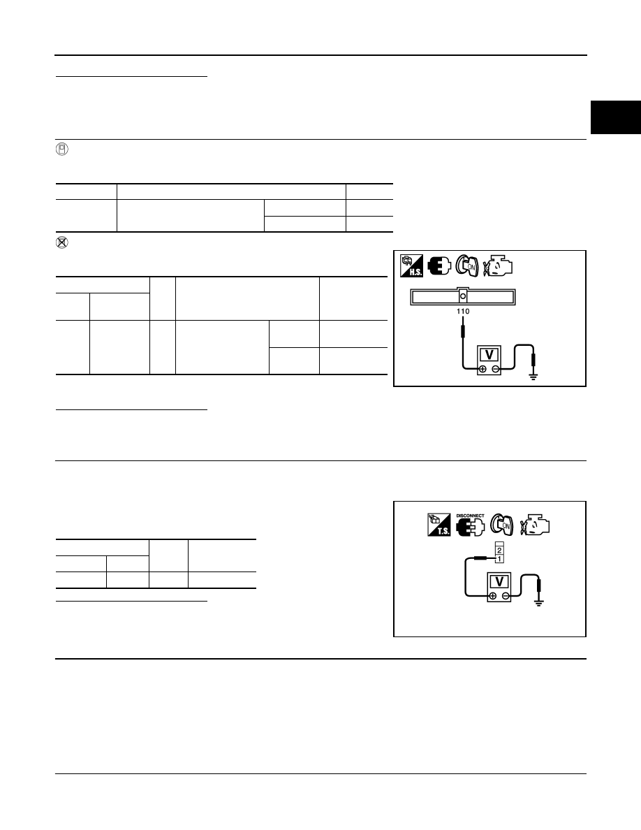
ECM
Gro
und
Condition
Voltage
Con-
nector
Terminal
E10
110
(ASCD
brake switch
signal)
Gro
und
Brake pedal (CVT)
Brake pedal and
clutch pedal (M/T)
Slightly
depressed
Approx. 0V
Fully re-
leased
Battery voltage
JMBIA1605ZZ
ASCD brake switch
Ground
Voltage
Connector Terminal
E37
1
Ground Battery voltage
PBIB0857E