Nissan Altima L32. Manual - part 426


  Index      Nissan     Nissan Altima L32 (2007-2009 year) - Service and Repair Manual


Search            


Content   ..  424  425  426  427   ..


Nissan Altima L32. Manual - part 426


P0452 EVAP CONTROL SYSTEM PRESSURE SENSOR

EC-825

< COMPONENT DIAGNOSIS >

[QR25DE EXCEPT FOR CALIFORNIA]

C

D

E

F

G

H

I

J

K

L

M

A

EC

N

P

O

P0452 EVAP CONTROL SYSTEM PRESSURE SENSOR

Description

INFOID:0000000004349786

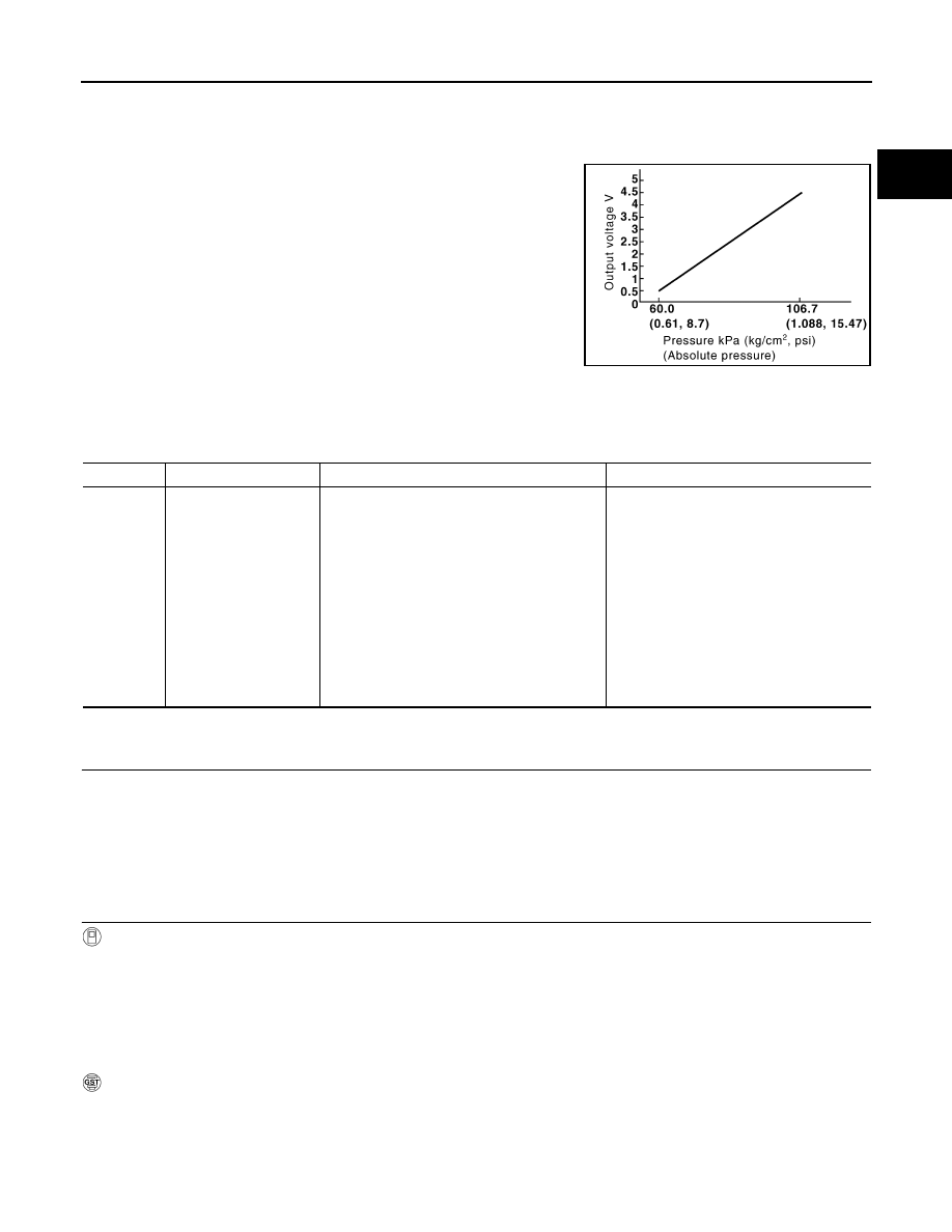
The EVAP control system pressure sensor detects pressure in the

purge line. The sensor output voltage to the ECM increases as pres-

sure increases.

DTC Logic

INFOID:0000000004349787

DTC DETECTION LOGIC

DTC CONFIRMATION PROCEDURE

1.

PRECONDITIONING

If DTC Confirmation Procedure has been previously conducted, always turn ignition switch OFF and wait at

least 10 seconds before conducting the next test.

TESTING CONDITION:

Always perform test at a temperature of 5

°C (41°F) or more.

>> GO TO 2.

2.

PERFORM DTC CONFIRMATION PROCEDURE

With CONSULT-III

1. Start engine and warm it up to normal operating temperature.

2. Turn ignition switch OFF and wait at least 10 seconds.

3. Turn ignition switch ON.

4. Select “DATA MONITOR” mode with CONSULT-III.

5. Make sure that “FUEL T/TMP SE” is more than 0

°C (32°F).

6. Start engine and wait at least 20 seconds.

7. Check 1st trip DTC.

With GST

1. Start engine and warm it up to normal operating temperature.

PBIB3370E

DTC No.

Trouble diagnosis name

DTC detecting condition

Possible cause

P0452

EVAP control system 
pressure sensor low in-
put

An excessively low voltage from the sensor is 
sent to ECM.

• Harness or connectors

(EVAP control system pressure sensor 
circuit is open or shorted.)
[Crankshaft position sensor (POS) circuit 
is shorted.)
(Accelerator pedal position sensor circuit 
is shorted.)
(Refrigerant pressure sensor circuit is 
shorted.)

• EVAP control system pressure sensor
• Crankshaft position sensor (POS)
• Accelerator pedal position sensor
• Refrigerant pressure sensor

EC-826

< COMPONENT DIAGNOSIS >

[QR25DE EXCEPT FOR CALIFORNIA]

P0452 EVAP CONTROL SYSTEM PRESSURE SENSOR

2. Set voltmeter probes to ECM harness connector and ground as

follows.

3. Make sure that the voltage is less than 4.2V.

4. Turn ignition switch OFF and wait at least 10 seconds.

5. Start engine and wait at least 20 seconds.

6. Check 1st trip DTC.
Is 1st trip DTC detected?

YES

>> Go to 

EC-826, "Diagnosis Procedure"

.

NO

>> INSPECTION END

Diagnosis Procedure

INFOID:0000000004349788

1.

CHECK GROUND CONNECTION

1. Turn ignition switch OFF.

2. Check ground connection E9. Refer to Ground Inspection in 

GI-45, "Circuit Inspection"

.

Is the inspection result normal?

YES

>> GO TO 2.

NO

>> Repair or replace ground connection.

2.

CHECK CONNECTOR

1. Disconnect EVAP control system pressure sensor harness connector.

2. Check sensor harness connector for water.

Is the inspection result normal?

YES

>> GO TO 3.

NO

>> Repair or replace harness connector.

3.

CHECK EVAP CONTROL SYSTEM PRESSURE SENSOR POWER SUPPLY CIRCUIT-I

1. Turn ignition switch ON.

2. Check the voltage between EVAP control system pressure sen-

sor harness connector and ground.

Is the inspection result normal?

YES

>> GO TO 10.

NO

>> GO TO 4.

4.

CHECK EVAP CONTROL SYSTEM PRESSURE SENSOR POWER SUPPLY CIRCUIT-II

1. Turn ignition switch OFF.

2. Disconnect ECM harness connector.

3. Check the continuity between EVAP control system pressure sensor harness connector and ECM har-

ness connector.

ECM

Ground

Connector

Terminal

E10

95

(Fuel tank temperature sensor signal)

Ground

PBIB0675E

Water should not exist.

EVAP control system pressure sensor

Ground

Voltage

Connector

Terminal

B41

3

Ground

Approx. 5V

PBIB0138E

P0452 EVAP CONTROL SYSTEM PRESSURE SENSOR

EC-827

< COMPONENT DIAGNOSIS >

[QR25DE EXCEPT FOR CALIFORNIA]

C

D

E

F

G

H

I

J

K

L

M

A

EC

N

P

O

Is the inspection result normal?

YES

>> GO TO 6.

NO

>> GO TO 5.

5.

DETECT MALFUNCTIONING PART

Check the following.

• Harness connectors B10, E29

• Harness for open or short between EVAP control system pressure sensor and ECM

>> Repair open circuit or short to ground or short to power in harness or connectors.

6.

CHECK SENSOR POWER SUPPLY CIRCUITS

Check harness for short to power and short to ground, between the following terminals.

Is the inspection result normal?

YES

>> GO TO 7.

NO

>> Repair short to ground or short to power in harness or connectors. 

7.

CHECK COMPONENTS

Check the following.

• Crankshaft position sensor (POS) (Refer to 

EC-786, "Component Inspection"

.)

• Refrigerant pressure sensor (Refer to 

EC-975, "Diagnosis Procedure"

.)

Is the inspection result normal?

YES

>> GO TO 8.

NO

>> Replace malfunctioning component.

8.

CHECK APP SENSOR

Refer to 

EC-926, "Component Inspection"

.

Is the inspection result normal?

YES

>> GO TO 10.

NO

>> GO TO 9.

9.

REPLACE ACCELERATOR PEDAL ASSEMBLY

1. Replace accelerator pedal assembly

2. Go to 

EC-926, "Special Repair Requirement"

.

>> INSPECTION END

10.

CHECK EVAP CONTROL SYSTEM PRESSURE SENSOR GROUND CIRCUIT FOR OPEN AND

SHORT

1. Turn ignition switch OFF.

2. Disconnect ECM harness connector.

3. Check the continuity between EVAP control system pressure sensor harness connector and ECM har-

ness connector.

EVAP control system pressure 

sensor

ECM

Continuity

Connector

Terminal

Connector

Terminal

B41

3

E10

91

Existed

ECM

Sensor

Connector

Terminal

Name

Connector

Terminal

F13

72

Refrigerant pressure sensor

E219

1

76

CKP sensor (POS)

F30

1

E10

87

APP sensor

E40

6

91

EVAP control system pressure sensor

B41

3

EC-828

< COMPONENT DIAGNOSIS >

[QR25DE EXCEPT FOR CALIFORNIA]

P0452 EVAP CONTROL SYSTEM PRESSURE SENSOR

4. Also check harness for short to ground and short to power.
Is the inspection result normal?

YES

>> GO TO 12.

NO

>> GO TO 11.

11.

DETECT MALFUNCTIONING PART

Check the following.

• Harness connectors B10, E29

• Harness for open or short between EVAP control system pressure sensor and ECM

>> Repair open circuit or short to ground or short to power in harness or connectors.

12.

CHECK EVAP CONTROL SYSTEM PRESSURE SENSOR INPUT SIGNAL CIRCUIT FOR OPEN AND

SHORT
1. Check the continuity between EVAP control system pressure sensor harness connector and ECM har-

ness connector.

2. Also check harness for short to ground and short to power.
Is the inspection result normal?

YES

>> GO TO 14.

NO

>> GO TO 13.

13.

DETECT MALFUNCTIONING PART

Check the following.

• Harness connectors B10, E29

• Harness for open or short between EVAP control system pressure sensor and ECM

>> Repair open circuit or short to ground or short to power in harness or connectors.

14.

CHECK EVAP CONTROL SYSTEM PRESSURE SENSOR

Refer to 

EC-828, "Component Inspection"

.

Is the inspection result normal?

YES

>> GO TO 15.

NO

>> Replace EVAP control system pressure sensor.

15.

CHECK INTERMITTENT INCIDENT

Refer to 

GI-42, "Intermittent Incident"

.

>> INSPECTION END

Component Inspection

INFOID:0000000004349789

1.

CHECK EVAP CONTROL SYSTEM PRESSURE SENSOR

1. Turn ignition switch OFF.

2. Remove EVAP control system pressure sensor with its harness connector connected from EVAP canister.

Always replace O-ring with a new one.

EVAP control system pressure 

sensor

ECM

Continuity

Connector

Terminal

Connector

Terminal

B41

1

E10

96

Existed

EVAP control system pressure 

sensor

ECM

Continuity

Connector

Terminal

Connector

Terminal

B41

2

E10

86

Existed


Content   ..  424  425  426  427   ..