Nissan Altima L32. Manual - part 364
MULTIPORT FUEL INJECTION SYSTEM
EC-577
< FUNCTION DIAGNOSIS >
[QR25DE EXCEPT FOR CALIFORNIA]
C
D
E
F
G
H
I
J
K
L
M
A
EC
N
P
O
MULTIPORT FUEL INJECTION SYSTEM
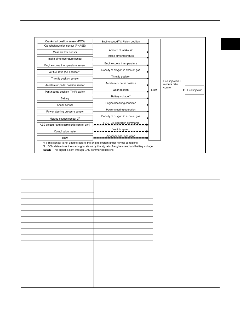
System Diagram
INFOID:0000000004349604
System Description
INFOID:0000000004349605
INPUT/OUTPUT SIGNAL CHART
*1: This sensor is not used to control the engine system under normal conditions.
*2: This signal is sent to the ECM through CAN communication line.
JMBIA0173GB
Sensor
Input Signal to ECM
ECM function
Actuator
Crankshaft position sensor (POS)
Engine speed*
3
Piston position
Fuel injection
& mixture ratio
control
Fuel injector
Camshaft position sensor (PHASE)
Mass air flow sensor
Amount of intake air
Intake air temperature sensor
Intake air temperature
Engine coolant temperature sensor
Engine coolant temperature
Air fuel ratio (A/F) sensor 1
Density of oxygen in exhaust gas
Throttle position sensor
Throttle position
Accelerator pedal position sensor
Accelerator pedal position
Park/neutral position (PNP) switch
Gear position
Battery
Battery voltage*
3
Knock sensor
Engine knocking condition
Power steering pressure sensor
Power steering operation
Heated oxygen sensor 2*
1
Density of oxygen in exhaust gas
ABS actuator and electric unit (control unit)*
2
ABS operation command
BCM
Air conditioner operation*
2
Combination meter
Vehicle speed*
2