Nissan Altima L32. Manual - part 327
P2122, P2123 APP SENSOR
EC-429
< COMPONENT DIAGNOSIS >
[QR25DE FOR CALIFORNIA]
C
D
E
F
G
H
I
J
K
L
M
A
EC
N
P
O
>> INSPECTION END
Component Inspection
INFOID:0000000004349486
1.
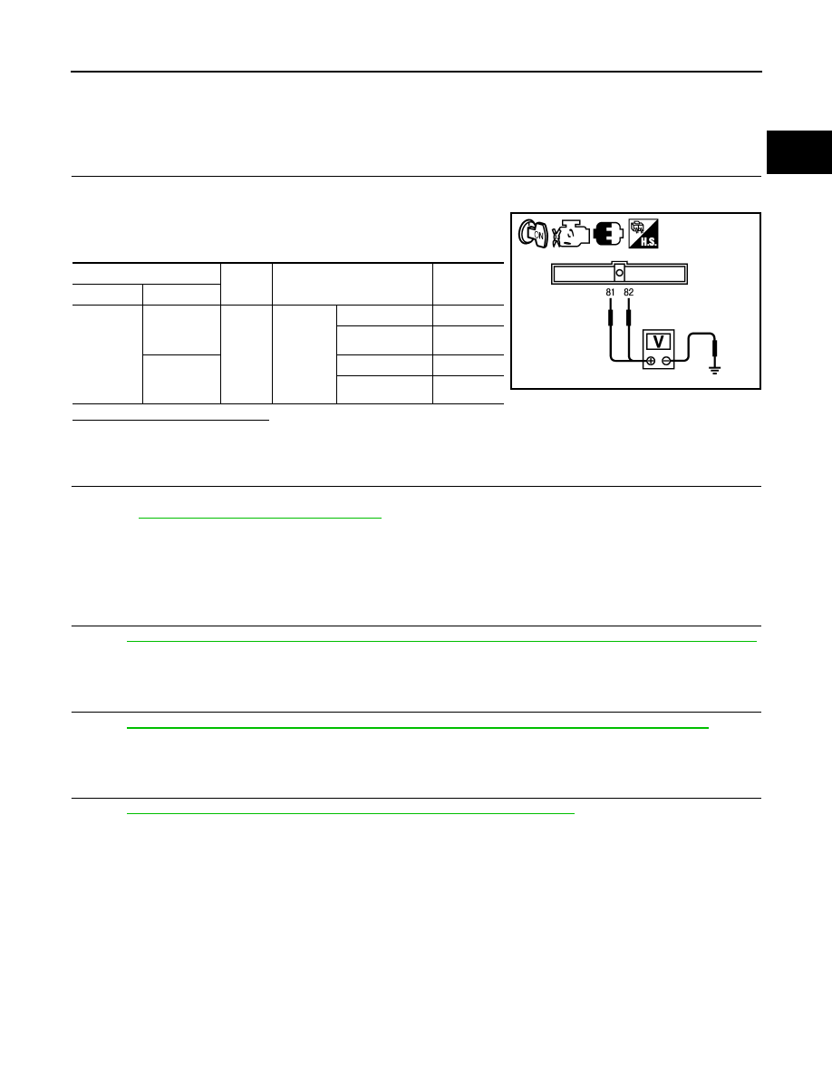
CHECK ACCELERATOR PEDAL POSITION SENSOR
1. Reconnect all harness connectors disconnected.
2. Turn ignition switch ON.
3. Check the voltage between ECM harness connector and
ground.
Is the inspection result normal?
YES
>> INSPECTION END
NO
>> GO TO 2.
2.
REPLACE ACCELERATOR PEDAL ASSEMBLY
1. Replace accelerator pedal assembly.
2. Go to
EC-429, "Special Repair Requirement"
.
>> INSPECTION END
Special Repair Requirement
INFOID:0000000004349487
1.
PERFORM ACCELERATOR PEDAL RELEASED POSITION LEARNING
Refer to
EC-29, "ACCELERATOR PEDAL RELEASED POSITION LEARNING : Special Repair Requirement"
.
>> GO TO 2.
2.
PERFORM THROTTLE VALVE CLOSED POSITION LEARNING
EC-29, "THROTTLE VALVE CLOSED POSITION LEARNING : Special Repair Requirement"
>> GO TO 3.
3.
PERFORM IDLE AIR VOLUME LEARNING
EC-30, "IDLE AIR VOLUME LEARNING : Special Repair Requirement"
>> END
ECM
Ground
Condition
Voltage
Connector
Terminal
E40
81
(APP sen-
sor 1 signal)
Ground
Accelera-
tor pedal
Fully released
0.5 - 1.0 V
Fully depressed
4.2 - 4.8 V
82
(APP sen-
sor 2 signal)
Fully released
0.25 - 0.5 V
Fully depressed
2.0 - 2.5 V
PBIB3604E