Nissan Altima L32. Manual - part 247
 

  Index      Nissan     Nissan Altima L32 (2007-2009 year) - Service and Repair Manual


Search            


Content   ..  245  246  247  248   ..


Nissan Altima L32. Manual - part 247


TUMBLE CONTROL VALVE CONTROL

EC-109

< FUNCTION DIAGNOSIS >

[QR25DE FOR CALIFORNIA]

C

D

E

F

G

H

I

J

K

L

M

A

EC

N

P

O

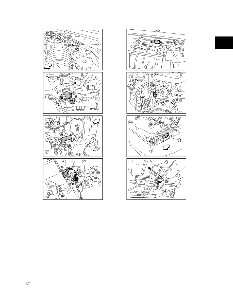
1.

EVAP service port

2.

Intake air duct

3.

EVAP canister purge volume control so-
lenoid valve

4.

Intake manifold collector

5.

Park/neutral position (PNP) switch (CVT) 
(This illustration is view with air cleaner 
assembly removed.)

6.

Park/neutral position (PNP) switch (M/T) 
(This illustration is view with air cleaner 
assembly removed.)

7.

Intake valve timing control 
solenoid valve
(This illustration is view with 
engine removed.)

8.

Exhaust manifold cover

9.

Air fuel ratio (A/F) sensor 1

10. Air fuel ratio (A/F) sensor 1 

harness connector

11. Heated oxygen sensor 2

(This illustration is view from under vehi-
cle.)

12. Heated oxygen sensor 2 harness con-

nector
(This illustration is view from under vehi-
cle.)

13. Engine oil pan

14. Heated oxygen sensor 3

(This illustration is view form under vehi-
cle.)

15. Heated oxygen sensor 3 harness con-

nector
(This illustration is view from under vehi-
cle.)

: Vehicle front

ALBIA0092ZZ

EC-110

< FUNCTION DIAGNOSIS >

[QR25DE FOR CALIFORNIA]

TUMBLE CONTROL VALVE CONTROL

1.

Thermostat housing

2.

Tumble control valve actuator

3.

Throttle valve
(This illustration is view with intake 
air duct removed.)

4.

Electric throttle control actuator

5.

Fuel injector harness connector

6.

Condenser-2

7.

Radiator hose (upper)

8.

Battery

9.

ECM

10. Fuel level sensor unit and fuel pump 

harness connector
(This illustration is view with rear 
seat cushion and inspection hole 
cover removed.)

11. Fuel level sensor unit and fuel pump 

assembly

12. Fuel pressure regulator

13. Fuel tank temperature sensor

14. EVAP control system pressure sen-

sor (This illustration is view with rear 
suspension member removed.)

15. EVAP canister vent control valve

(This illustration is view with rear 
suspension member removed.)

16. EVAP canister

(This illustration is view with rear 
suspension member removed.)
: Vehicle front

ALBIA0093ZZ

TUMBLE CONTROL VALVE CONTROL

EC-111

< FUNCTION DIAGNOSIS >

[QR25DE FOR CALIFORNIA]

C

D

E

F

G

H

I

J

K

L

M

A

EC

N

P

O

Component Description

INFOID:0000000004349179

1.

No.1 ignition coil

2.

Cooling fan motor-1 harness con-
nector

3.

Cooling fan motor-2 harness con-
nector

4.

Refrigerant pressure sensor

5.

Accelerator pedal position sensor

6.

ASCD brake switch

7.

Stop lamp switch

8.

Brake pedal

9.

ASCD clutch switch

10. Clutch pedal

11. ASCD steering switch

12. CANSEC switch

13. RESUME/ACCELERATE switch

14. SET/COAST switch

15. MAIN switch

: Vehicle front

ALBIA0089ZZ

Component

Reference

Tumble control valve

EC-409, "Description"

Tumble control valve position sensor

EC-409, "Description"

EC-112

< FUNCTION DIAGNOSIS >

[QR25DE FOR CALIFORNIA]

ON BOARD DIAGNOSTIC (OBD) SYSTEM

ON BOARD DIAGNOSTIC (OBD) SYSTEM

Diagnosis Description

INFOID:0000000004349180

INTRODUCTION

The ECM has an on board diagnostic system, which detects malfunctions related to engine sensors or actua-

tors. The ECM also records various emission-related diagnostic information including:

The above information can be checked using procedures listed in the table below.

×: Applicable —: Not applicable

*: When DTC and 1st trip DTC simultaneously appear on the display, they cannot be clearly distinguished from each other.

The malfunction indicator lamp (MIL) on the instrument panel lights up when the same malfunction is detected

in two consecutive trips (Two trip detection logic), or when the ECM enters fail-safe mode. (Refer to 

EC-523,

"Fail Safe"

.)

TWO TRIP DETECTION LOGIC

When a malfunction is detected for the first time, 1st trip DTC and 1st trip Freeze Frame data are stored in the

ECM memory. The MIL will not light up at this stage. <1st trip>

If the same malfunction is detected again during the next drive, the DTC and Freeze Frame data are stored in

the ECM memory, and the MIL lights up. The MIL lights up at the same time when the DTC is stored. <2nd

trip> The “trip” in the “Two Trip Detection Logic” means a driving mode in which self-diagnosis is performed

during vehicle operation. Specific on board diagnostic items will cause the ECM to light up or blink the MIL,

and store DTC and Freeze Frame data, even in the 1st trip, as shown below.

×: Applicable —: Not applicable

DTC AND FREEZE FRAME DATA

DTC and 1st Trip DTC

Emission-related diagnostic information

Diagnostic service

Diagnostic Trouble Code (DTC)

Service $03 of SAE J1979

Freeze Frame data

Service $02 of SAE J1979

System Readiness Test (SRT) code

Service $01 of SAE J1979

1st Trip Diagnostic Trouble Code (1st Trip DTC)

Service $07 of SAE J1979

1st Trip Freeze Frame data

Test values and Test limits

Service $06 of SAE J1979

Calibration ID

Service $09 of SAE J1979

DTC

1st trip DTC

Freeze 

Frame data

1st trip Freeze 

Frame data

SRT code

SRT status

Test value

CONSULT-III

×

×

×

×

×

×

GST

×

×

×

×

×

×

ECM

×

×*

×

Items

MIL

DTC

1st trip DTC

1st trip

2nd trip 

1st trip 

displaying

2nd trip 

displaying

1st trip 

displaying

2nd trip 

display-

ing

Blinking

Lighting 

up

Blinking

Lighting 

up

Misfire (Possible three way catalyst 
damage) — DTC: P0300 - P0304 is 
being detected

×

×

Misfire (Possible three way catalyst 
damage) — DTC: P0300 - P0304 is 
being detected

×

×

One trip detection diagnoses (Re-
fer to 

EC-527, "DTC Index"

.)

×

×

Except above

×

×

×


Content   ..  245  246  247  248   ..