Nissan Altima L32. Manual - part 1581


  Index      Nissan     Nissan Altima L32 (2007-2009 year) - Service and Repair Manual


Search            


Content   ..  1579  1580  1581  1582   ..


Nissan Altima L32. Manual - part 1581


ROAD WHEEL TIRE ASSEMBLY

WT-67

< ON-VEHICLE REPAIR >

C

D

F

G

H

I

J

K

L

M

A

B

WT

N

O

P

c. If calculated balance weight value exceeds 50 g (1.76 oz.),

install two balance weight sheets in line with each other as

shown.

CAUTION:

Do not install one balance weight sheet on top of another.

5. Start wheel balancer again.
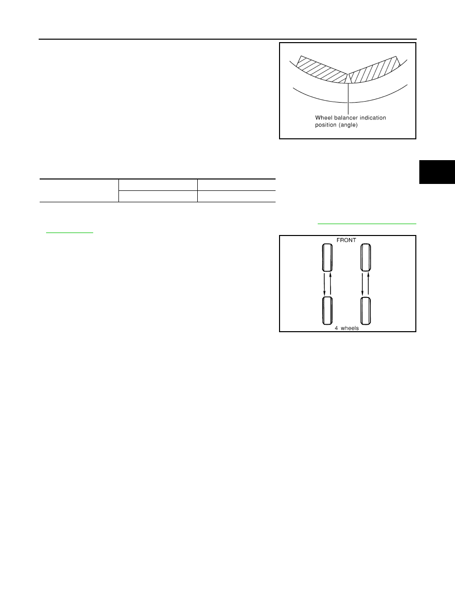
6. Install drive-in balance weight on inner side of road wheel in the

wheel balancer indication position (angle).

CAUTION:

Do not install more than two balance weights.

7. Start wheel balancer. Make sure that inner and outer residual

unbalance values are 5 g (0.18 oz.) each or below.

• If either residual unbalance value exceeds 5 g (0.18 oz.), repeat installation procedures.

Wheel balance (Maximum allowable unbalance):

TIRE ROTATION

• Follow the maintenance schedule for tire rotation service intervals. Refer to 

MA-4, "Explanation General

Maintenance"

.

• Do not include the T-type spare tire when rotating the tires.

CAUTION:

• When installing wheels, tighten them diagonally by dividing

the work two to three times in order to prevent the wheels

from developing any distortion.

• Be careful not to tighten wheel nut at torque exceeding the

criteria for preventing strain of disc rotor.

Maximum allowable un-
balance

Dynamic (At rim flange)

5 g (0.18 oz.) (one side)

Static

10 g (0.35 oz.)

SMA056D

Tightening torque of 
wheel nut

: 113 N·m (12 kg-m, 83 ft-lb)

SMA829C

WT-68

< REMOVAL AND INSTALLATION >

TRANSMITTER

REMOVAL AND INSTALLATION

TRANSMITTER

Removal and Installation

INFOID:0000000004205329

REMOVAL

1. Remove wheel and tire using power tool.
2. Deflate tire. Unscrew transmitter retaining nut and allow transmitter to fall into tire.
3. Gently bounce tire so that transmitter falls to bottom of tire.

Place wheel and tire assembly on tire changing machine and

break both tire beads. Ensure that the transmitter remains at the

bottom of the tire while breaking the bead.

4. Turn tire so that valve hole is at bottom, and gently bounce the

tire to ensure transmitter is near valve hole. Carefully lift tire onto

turntable and position valve hole (and transmitter) 270 degrees

from mounting/dismounting head.

5. Lubricate tire well, and remove top side of tire. Reach inside the

tire and remove the transmitter.

6. Remove the second side of the tire as normal.

INSTALLATION

1. Place first side of tire onto rim.

2. Apply suitable silicone lubricant to new transmitter seal then install seal on transmitter. Refer to 

MA-12,

"Fluids and Lubricants"

.

NOTE:

Always replace the seal after every disassembly.

SEIA0047E

WEIA0046E

SEIA0049E

TRANSMITTER

WT-69

< REMOVAL AND INSTALLATION >

C

D

F

G

H

I

J

K

L

M

A

B

WT

N

O

P

3. Mount transmitter on rim and tighten nut at a maximum speed of

10 rpm.

NOTE:

Make sure no burrs exist in the valve stem hole of the wheel.

4. Place wheel on turntable of tire machine. Ensure that transmitter

is 270 degrees from mounting/dismounting head.

NOTE:

Do not touch transmitter with mounting head.

5. Lubricate tire well, and install second side of tire as normal.

Ensure that tire does not rotate relative to rim.

6. Inflate tire and balance the wheel and tire assembly. Refer to

WT-66, "Adjustment"

.

7. Install wheel and tire assembly in appropriate wheel position on

vehicle. Refer to 

WT-66, "Adjustment"

.

NOTE:

If replacing the transmitter, then transmitter wake up operation

must be performed. Refer to 

WT-5, "Transmitter Wake Up Operation"

.

8. Adjust neutral position of steering angle sensor. Refer to 

BRC-143, "ADJUSTMENT OF STEERING

ANGLE SENSOR NEUTRAL POSITION : Special Repair Requirement"

.

Transmitter nut 
tightening torque

: 7.7 N·m (0.79 kg-m, 68 in-lb)

WEIA0137E

WEIA0046E

WT-70

< SERVICE DATA AND SPECIFICATIONS (SDS) 

SERVICE DATA AND SPECIFICATIONS (SDS)

SERVICE DATA AND SPECIFICATIONS (SDS)

SERVICE DATA AND SPECIFICATIONS (SDS)

Road Wheel

INFOID:0000000004205330

Tire

INFOID:0000000004205331

Unit: kPa (kg/cm

2

, psi)

Standard item

Allowable value

Aluminum

Steel

Maximum radial 
runout limit

Lateral deflection

Less than 0.3 mm (0.012 in) Less than 1.5 mm (0.059 in)

Radial deflection

Less than 0.3 mm (0.012 in) Less than 1.5 mm (0.059 in)

Maximum allowable 
unbalance

Dynamic
 (At rim flange)

Less than 5 g (0.18 oz) (one side)

Static
 (At rim flange)

Less than 10 g (0.35 oz)

Tire size

Air pressure 

Front tire

Rear tire

P215/60R16

220 (2.2, 32)

220 (2.2, 32)

P215/55R17

230 (2.3, 33)

230 (2.3, 33)

P235/45R18

230 (2.3, 33)

230 (2.3, 33)

T135/70R16

420 (4.2, 60)

420 (4.2, 60)

T135/90D16

420 (4.2, 60)

420 (4.2, 60)


Content   ..  1579  1580  1581  1582   ..